Close
0%
0%

piPOV

A rotary POV display using the Pi Zero.

Similar projects worth following
A Pi Zero is used to make a low-cost and easy to build rotary POV display. Uses include a clock or status display.

THE DESIGN PROCESS

I've always wanted to build a rotating POV display, and had gone so far as to order some surface mount LEDs, but never came up with a satisfactory method to transfer power to the rotating part. With the availability of the Pi Zero my interest was revived, so I decided to compromise and mount a battery along with the Pi Zero as a workaround. Then I ran across this kit which prompted me to do my usual design review.

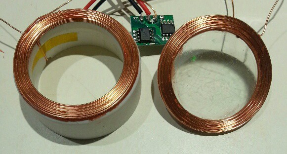
First I looked at the power transfer. The kit uses a rotary transformer, made up from a large ferrite bead and hand wound coils. I was NOT looking forward to winding coils and making driver circuits. Then I realised I already had a complete solution on hand - an Adafruit inductive charging set I'd bought for another project. Problem solved!

The motor looked like a cheap brushed type, and I didn't think it would last long in use, so I decided to replace it with a brushless one. Candidates included the spindle motor from a hard disk, the spindle motor from a CD drive, or a brushless DC fan. The hard disk motor would interfere with the charging set (the hub is aluminum), so it was out. The CD motor would work, but I'd have to buy a $7.00 ESC to drive it. I was left with the fan. I was worried about the lack of ridigity, but after some testing it seemed OK.

I didn't need the top display, so that could be eliminated. I could eliminate the chip resistors and instead use leaded resistors from the LED board to the Zero's gpio holes. These would also hold the board rigidly to the Zero. The board would be quite easy to design and should cost under $5.00.

Holding the coils in position should be easy, and the Zero would mount on top of the rotating coil. I decided to test later to see if the magnetic field from the coil will induce any harmful currents in the Zero. If it did it would always be possible to shield it.

The Zero would be mounted off-center to make the display diameter as large as possible. As in the kit it would need some counterweights, but those could be easily attached to the Zero mounting holes.

The IR sync method of the kit should work, and the parts for it could probably be salvaged from a mouse scroll wheel. Bluetooth could be used instead of the IR remote.

Existing Python POV software should work, or I could write a kernel module using DMA.

All sorted. Time to build it!

NAYSAYER NOTES: Yes, this will cost a bit more than the kit. But I wouldn't learn anything that way except maybe some soldering practice (which I don't need), and how to use the Arm programming environment provided with the kit. Frankly, I'd rather write my own code in a familiar environment instead.
piPOV.cmp

KiCad footprint assignment

CustomMenu - 3.34 kB - 03/22/2016 at 01:49

Download

piPOV.mod

KiCad footprint library

mod - 896.00 bytes - 03/22/2016 at 01:49

Download

piPOV.zip

OSHPark files

Zip Archive - 4.27 kB - 03/22/2016 at 01:49

Download

piPOV.kicad_pcb

KiCad board file

kicad_pcb - 35.08 kB - 03/22/2016 at 01:49

Download

piPOV.pro

KiCad project

pro - 826.00 bytes - 03/22/2016 at 01:49

Download

View all 8 files

  • 1 × Adafruit inductive charging set
  • 1 × Brushless DC fan. The hub (after blades are removed) must be smaller than the inside of the charging set coils by at least 2 mm.
  • 1 × IR receiver and matching LED. I salvaged them from a mouse scroll wheel.
  • 1 × 1" PVC pipe cap. Flat top preferred.
  • 1 × Some kind of base that silicone caulk will adhere to.

View all 6 components

  • files uploaded

    mincepi03/22/2016 at 01:58 0 comments

    Uploaded board design and OSHPark submission files.

    My Zero arrived today after being listed as "processing exception" status in New Your for several days. Sounds like something I'd encounter after running a wonky kernel module, not something involving shipping...

    Board is ordered. I'll order parts in the next couple days.

    I tested leakage from the inductive coupling. Magnetic shielding doesn't work, but a bit of aluminum tape should work, with only a little loading of the coil. The real test is to see if a Zero locks up when mounted. I've got my fingers crossed...

  • initial posting

    mincepi03/13/2016 at 17:56 0 comments

    Initial posting. I'm waiting for receipt of my Zero from Adafruit before proceeding with further assembly (it shipped today).

    Base with motor has been assembled and tested. Inductive charger has been tested and works.

    To Do: design circuit board and order, spec and order LEDs.

View all 2 project logs

  • 1
    Step 1

    Cut the fan hub out of the frame, then cut off the blades. PRO TIP: use some hot glue as a strain relief on the wires.They tend to break off easily with all the handling. Holding the motor against a bench belt sander and rotating it is a good way of removing the leftover bits of blade.

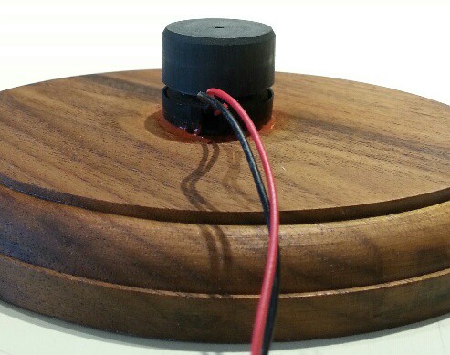
    Below is the fan motor cut down and mounted. I used silicone caulk to glue it to a base I had kicking around.

    Below are the coil mountings. The disc is cut from a CD and is the same diameter as the coil. The aluminum layer must be removed - put some tape on it and pull and it should come off. The hole is drilled for the inside wire of the coil.

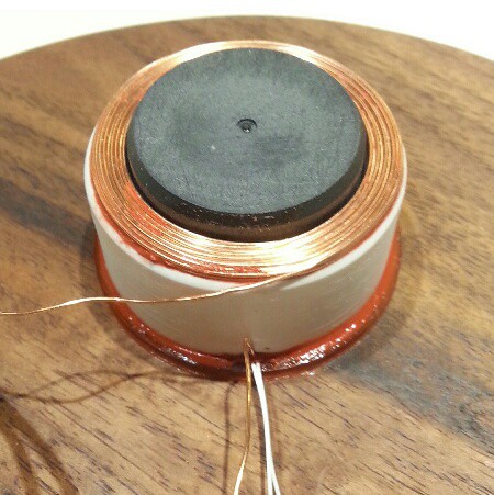
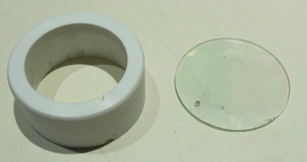
    The ring is a cut-down 1" PVC pipe cap. I used a metal lathe, but if you don't have one a bench belt sander can be used to shape it. The hole can be drilled to approximate size, then a 1" drum sander in a drill press can finish it off. The hole should be the same diameter as the inside of the coil. The ring height should be adjusted to position the lower coil 1 mm from the upper coil. Note the slots cut in it for the coil and fan wires.

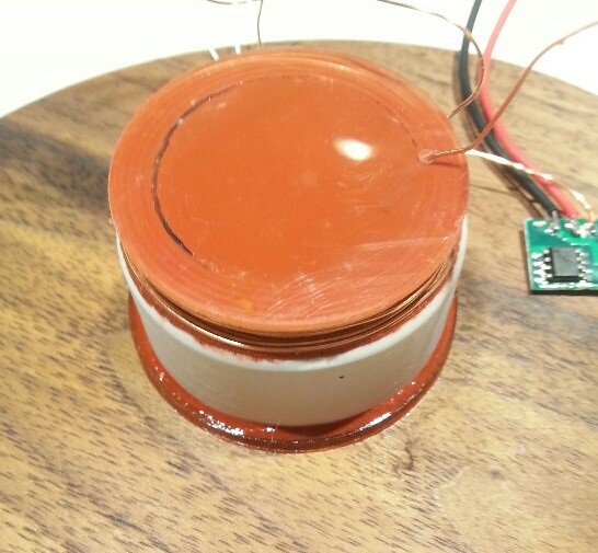
    Here's the coils mounted. Silicone caulk was used after the Kapton tape was removed from the coils.

    Here's the lower coil mounting glued to the base with silicone caulk. The white wires are for the fan motor: the originals broke off. NOT SHOWN: I shimmed the mounting temporarily with a strip of cardboard between the coil and the fan hub to keep everything centered while the caulk was curing.

    I then glued the upper coil on the fan hub with silicone caulk.

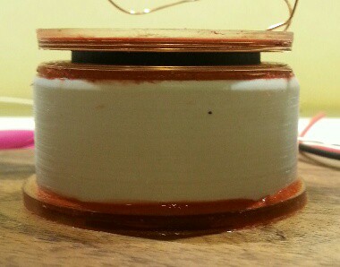
    Here you can see the coil spacing. If I did it again I'd make it about half this thickness.

  • 2
    Step 2

    ZERO MOUNTING

    NOTE: the following instructions are speculative. I haven't actually got a Zero yet to test them. I can see it in my head though.

    The power supply board is attached to the SD card socket with double sided foam tape. It's wired to the 5V and ground pins near it.

    4-40 standoffs are installed on the two holes by the SD card socket, one standoff on top and one standoff below for each of the two holes. The lower two standoffs are covered with heat shrink tubing.

    The LEDs are soldered to the circuit board following the markings. Resistors are soldered to the Zero then bent over and inserted into the LED board. Align the board so it's touching the corner of the Zero and is facing out from center then solder the resistor leads.

    The zero mounts on the disk with double sided foam tape. The heat shrink covered standoffs should touch the side of the coil.

    ...mount IR sensor

    ...wire base

    BALANCING

    Add nuts to the spacers to balance. More instructions soon...

View all instructions

Enjoy this project?

Share

Discussions

Similar Projects

Does this project spark your interest?

Become a member to follow this project and never miss any updates