Close
0%
0%

RigTig's Big 3D Printer

A DIY 3D printer (big volume, inexpensive, lightweight and portable).

Similar projects worth following
RigTig's Big 3D Printer (RB3DP) is a machine for placing material in 3 dimensions. The effector (printing head) hangs from three strings, each adjusted by a small stepper motor.

Many types of effectors are possible. Several have been tried with limited success, such as a 60ml syringe. This project is about refining the 3D positioning of a string-based 3D printer as well as getting useful effectors in the scale of metres rather than millimetres.

For an example use of the 3D printer, see https://hackaday.io/project/13442-3d-print-emergency-accommodation.

The prototype was tested at about a cubic metre and used an Arduino Nano to directly drive the 4 steppers. Scaling up required a total revamp. Now, each positioning motor has its own CPU with WiFi connection back to the central 2-CPU unit. A hand-held 2-CPU unit provides human control for calibration and testing.

RB3DP

Print volume is big: 1 to 100+ cubic metres.

Cost is small: less than US$100.

Speed is slow.

Accuracy is low.

It is a work-in-progress.

Big

The RB3DP can print bigger objects than most other 3D printers. One unusual characteristic is that the print base is triangular. The test prototype was somewhat less than a cubic metre. The second installation was about 5 cubic metres. The design is flexible about the size; it just needs enough string. Not yet tested, but 5 to 8 metres in each direction seems workable and probably even more. Each installation does need to be measured to calibrate the printer.

Inexpensive

The DIY cost to make a RB3DP is significantly less than one hundred dollars (USD100), plus 3D printed parts.

References

@Daren Schwenke  found this very up-to-date and relevant publication about cable supports:  https://www.researchgate.net/publication/316606621_On_the_effects_of_the_design_of_cable-Driven_robots_on_kinematics_and_dynamics_models_accuracy

x-fortran - 6.38 kB - 02/28/2017 at 22:27

Download

inc - 2.53 kB - 02/27/2017 at 22:11

Download

x-fortran - 753.00 bytes - 02/27/2017 at 22:06

Download

x-python - 1.06 kB - 02/27/2017 at 22:03

Download

Standard Tesselated Geometry - 2.45 MB - 09/04/2016 at 14:50

Download

View all 14 files

  • 1 × ESP14 For the GCODE interpreter (STM8) and the WiFi interface (ESP8266)
  • 4 × ESP8266 stepper driver https://hackaday.io/project/18533-esp8266-stepper-driver
  • 1 × beaded string Beads grip well so no slip on motor drives. I got mine from my wife's sewing stuff.
  • 3 × sets of 3D printed parts for motor block More details when I make time to publish them
  • 1 × effector Totally depends on what material is being printed. Simplest is a 60 mL syringe squeezed by threaded screw driven by stepper motor.

View all 6 components

  • Paper pulp extruder

    RigTig10/06/2017 at 06:36 0 comments

    This is a paper-making machine, reduced to create a 10mm strip of paper pulp, rolls around and around and around to build up a three-dimension object. This is the extruder part.

    Thought I'd lost these files, but found them on a USB, so I've put them up on https://www.myminifactory.com/object/46335. Still needs work, but if anyone wants to beat me to it, just go for it.

    Reworked a bit to suit laser sintering printer: see https://www.myminifactory.com/object/47744

  • Silicone extruder

    RigTig08/16/2017 at 05:44 0 comments

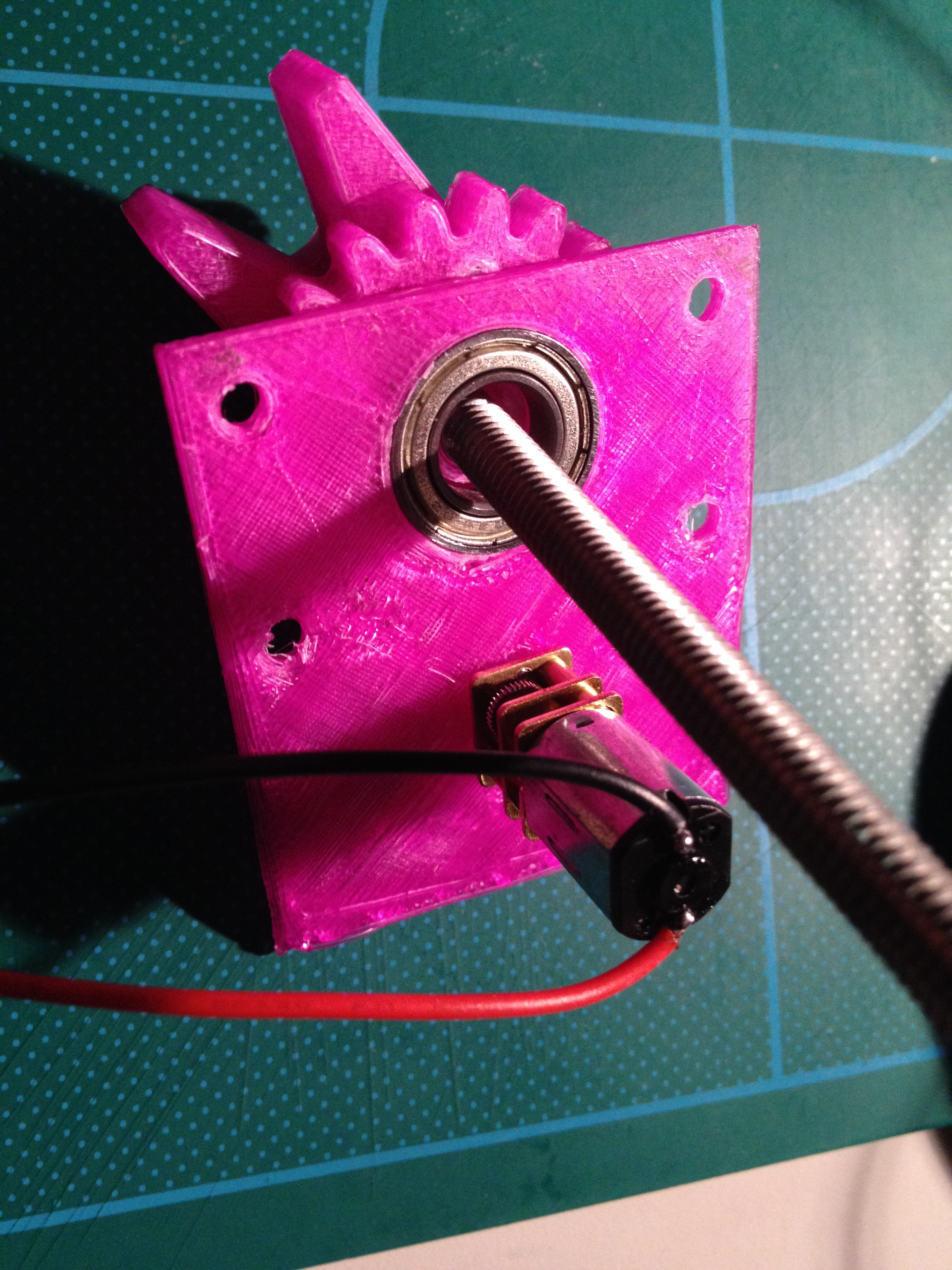
    A silicone gun is too hard to control using a computer, so I removed the handle and put on an extruder drive.  I used a tiny 100RPM 12V DC motor and it seems to have enough torque! More testing to come.

    And the 3D printed version looks like:

    And the motor (yes, it is a 6mm threaded rod):

    For more details, have a look at https://cad.onshape.com/documents/bdf821161c0d3c01945c5e17/w/145cfc7caf50a052aa41e42f/e/ac6f177acba94f862104b01a

  • An effector: a silicone gun

    RigTig07/09/2017 at 07:09 0 comments

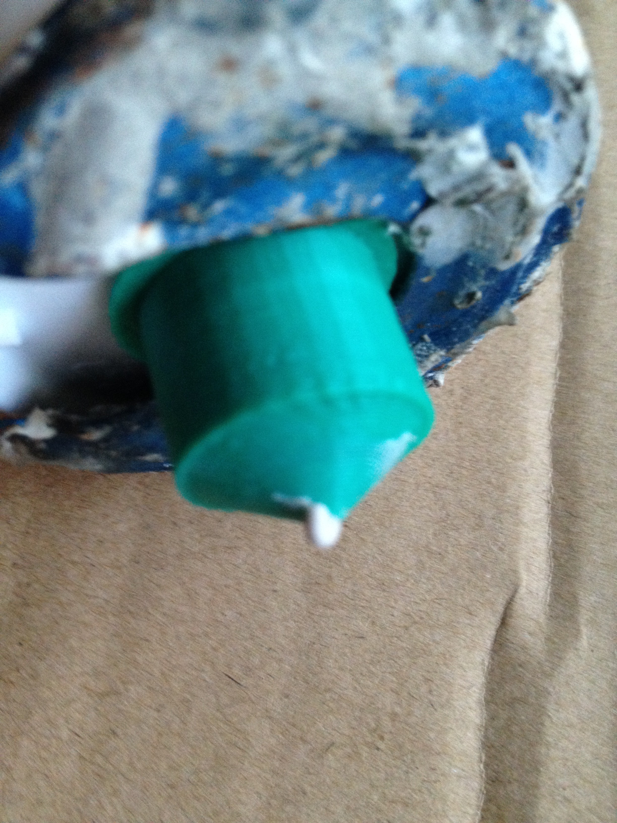
    The first effector was a 60ml syringe. This is just a bigger version really. I've got a project that needs to print about a meter square, but only 10 to 20 cm thick, and in something a bit softer than ABS and PLA. Lets try silicone. And what does a builder use to apply silicone? A: a silicone gun. So let's try it.

    Needed a nozzle about 1.5mm diameter, so I designed and printed one.

    use <~/installs/scad/simplethreads.scad>;
    
    nozzle();
    
    module nozzle() {
      difference() {
        union() {
          cylinder(d=23, h=1);
          cylinder(d=19, h=15);
          translate([0,0,15]) cylinder(r1=9, r2=1, h=5);
        }
        
        thread(3.0, 16.5, 12, 4.0, 0.3, true);
        translate([0,0,13]) cylinder(r1=8, r2=0.75, h=6);
        // hole
        cylinder(d=1.5, h=30);
      }
    }


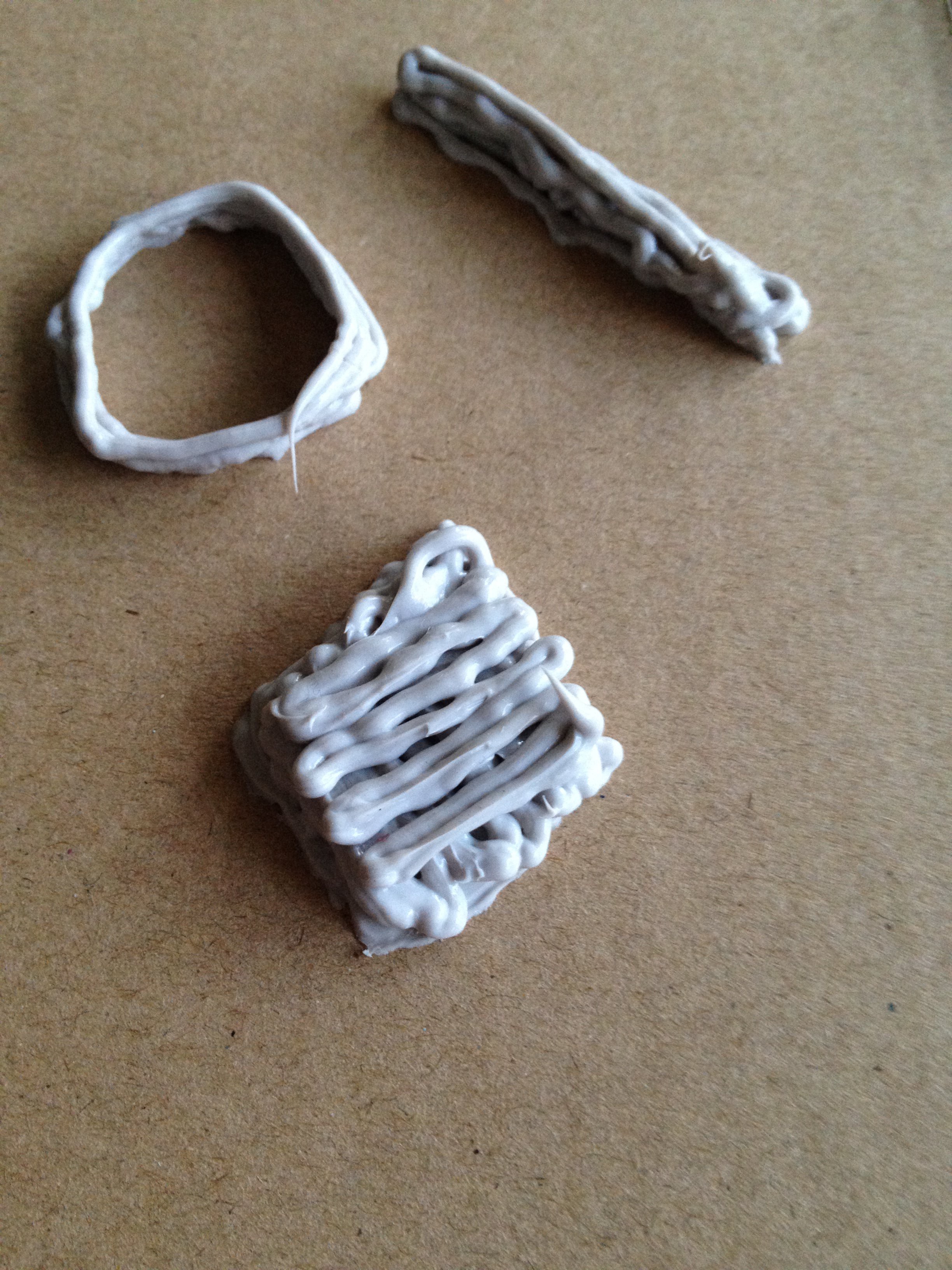
    How stable is a series of layers of silicone? Well, try it by hand and observe the results.

    Soft and squishy! And it looks like it'll hold up enough.

    OK, now to design a controllable squeezer for the cartridge. Mmm...need something with a bit more torque than the tiny steppers used earlier. Maybe I can try using an R/C motor and an ESC control.

    tbc...

  • Calibration with multilateration using W1209

    RigTig04/03/2017 at 00:52 4 comments

    To calibrate RB3DP, the idea is to set up a calibration object, manually move effector to 5 points on that object (at each point, record relative lengths to each winch) and calibration is just some arithmetic to derive the x, y, and z coordinates of each motor winch. So, we need a controller, which (of course) must be very inexpensive, so the choice is W1209 board (see https://hackaday.io/project/16097-eforth-for-cheap-stm8s-value-line-gadgets ) plus an ESP8266 for WiFi.

    The key for getting this to work is multilateration and the maths is on wikipedia (see https://en.wikipedia.org/wiki/Multilateration#Solution_with_limited_computational_resources). Many thanks to @Florian Festi for identifying multilateration as being a key solution to our calibration problem.

    The problem was that we did not know the lengths of the strings even if we knew the location of each of the motors (by physical measurement and typing them in). We can measure changes in length however, and that is what multilateration uses; differences in lengths. If you use 5 known points then you can calculate the cartesian coordinates of 3 motor winches. The origin is the one on the calibration object, so there is no transformation needed for different reference frames; everything is referenced to the object space. Another advantage is that there is no restriction on having the motor winches on a plane parallel to the baseplate. In fact, even the orientation of the axes is independent of the physical orientation of the motor winches.

    So, we need a calibration piece with points with known coordinates (P0 to P4), and we need a controller to make each motor winch move so its string is longer and shorter. Now, putting all the calibration code on the central GCODE interpreter might have been obvious, but actually putting code that is used for special purposes on a special purpose machine has the advantage of making this major function very cleanly interfaced. All we need to do at the end of the calibration is tell the GCODE interpreter the locations of the motor winches.

    And there is sure to be some additional functions we can add to the controller, such as moving the effector through a maze, and ...

  • Wobbling of effector

    RigTig03/25/2017 at 12:16 2 comments

    What is needed is a way to stop the wobble caused by acceleration of the effector, and possibly the drag of the extrusion material. Two sides of a parallelogram stay parallel even if the angle with the other two sides changes. So, how about we use two strings from each support so the parallelogram is in the vertical plane? Well, that means three attachment points higher and three lower to the effector. Strings can get shorter by folding up a bit, but are (relatively) inextensible. So the parallelograms should be stable enough. Mmm...ok at the effector, but what about the motors?

    Well, each motor now needs to wind in and out two strings at the same rate. One motor can handle that easily. Each spare string needs to be kept clear of the other, and still have an accumulator, and that seems to be a simple piece of engineering, too.

    There is no change to the kinematics needed, so software is unaffected.

    This whole idea was the result of just thinking further about a question asked by @Florian Festi in a reply to one of my comments on Someone please build a parallel cable robot over in https://hackaday.io/project/11583-odrive-high-performance-motor-control. Now, Florian might be disappointed that I have not reverted to kinematics more like a delta printer, but Florian should be pleased that I have been inspired to think further about stability of this printer. Thanks Florian, for making me think about delta printers.

    Oh, yeah, and if this idea doesn't work, it is nothing to do with Florian.

  • ESP14 is looking like a goer

    RigTig03/21/2017 at 11:36 0 comments

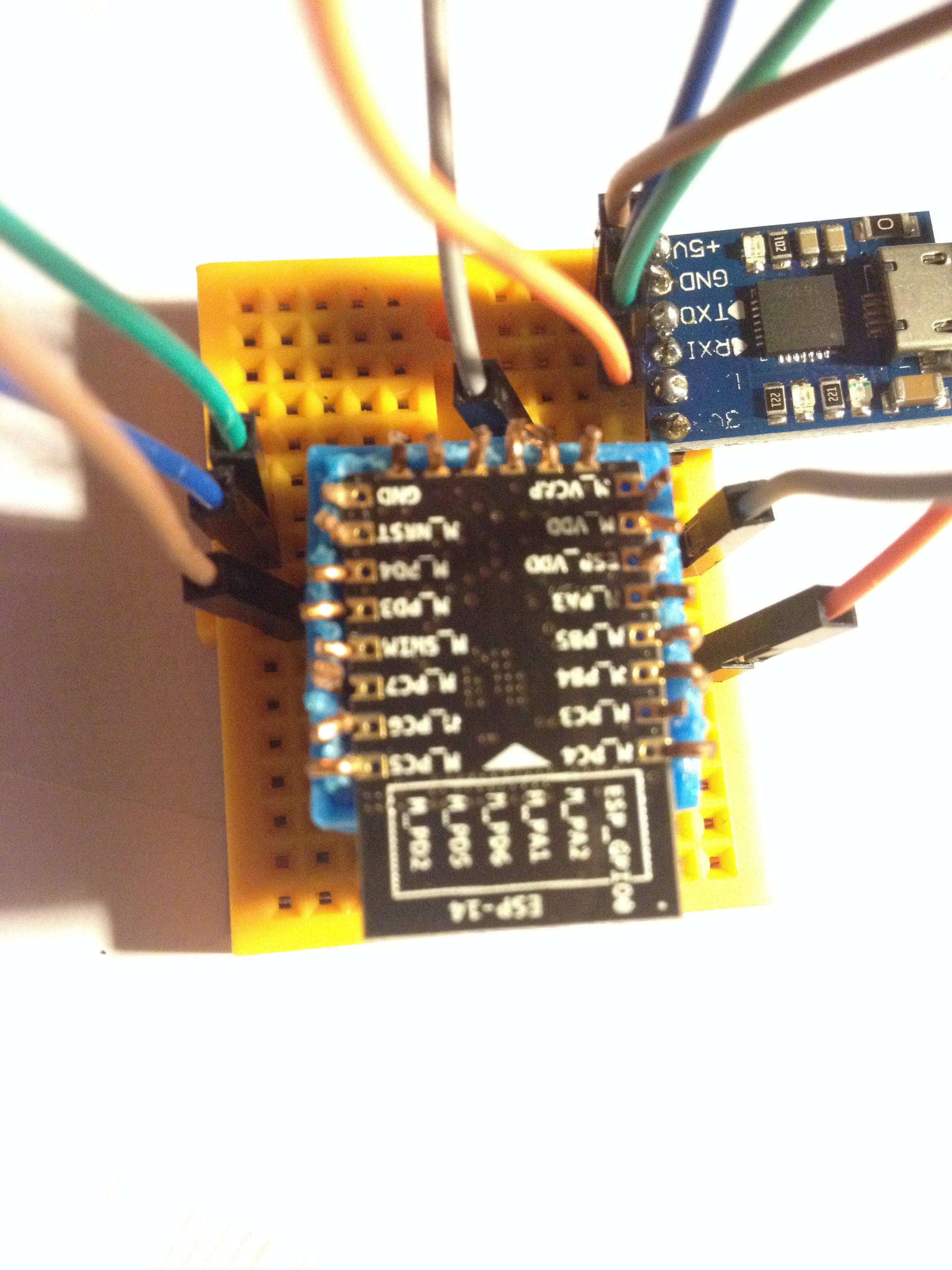
    The basic GCODE interpreter is about 90% coded onto the STM8 part of ESP14, with considerable thanks to @Thomas for his STM8EF forth interpreter. The comms part is also about 90% done on the ESP8266 part, with thanks to zeroflag for his punyforth. So here is a photo of the breadboard of ESP14 being programmed. Still running code in RAM until it works fully.

    Now, my job is to get back to the motor driver and get it to communicate with this ESP14. Since ESP14 is a wifi access point, I just need to connect ESP12 as dhcp client and set up the tcp channel through a chosen port (that's relatively easy). And then it is just a matter of getting both ends to behave properly when something (temporarily) interrupts communication (and that is the hard bit).

  • Concept test for controller on STM8

    RigTig02/27/2017 at 22:34 1 comment

    Sometimes smaller is better. Thanks @Thomas for eForth on STM8. I've added the files to this project where I have tested the concept of using STM8 running eForth to be the controller for the RB3DP. The forward and reverse kinematics routines are tested, and a few GCODE commands are implemented. Stubs are used for actual actions, with text echo of internal commands.

    Based on this test, RB3DP will accept GCODE in millimeters and have a maximum size of about 60 meters (the 16-bit integer maths maxes out at 65.535 meters).

    Now to put it all together on ESP14 (which is STM8 with ESP8266).

  • ESP14 as GCODE interpreter?

    RigTig02/23/2017 at 07:12 3 comments

    Rather than Arduino and ESP8266, I wonder if ESP14 might work as a GCODE interpreter. Mmm...looks like a job for Forth, so I got hold of eForth (for the STM8) from another hackaday.io project (thanks to Thomas @TG9541 - see https://hackaday.io/project/16097-eforth-for-cheap-stm8s-value-line-gadgets). It looks like the GCODE interpreter is going to be about 3K of code on top of about 4.5K of eForth. Not a fancy interpreter by any means but it'll work (I believe).

    I decided to implement each GCODE command as a Forth word. For example, the GCODE M17 command is to enable the motors, and has no parameters. Its implementation is trivial, as follows:

    : M17;
      \ enable motors
      motorsOn
      ;

    GCODE interpretation rules generally say to quietly ignore any GCODE command that does not apply to the particular machine, but Forth typically aborts operation if an unknown command is received. So, we want to change the outer interpreter. This is easy in eForth, thus:

    \ GCODE interpreter
    \ no prompt; ignore undefined words
    : GEV ( -- )
      NAME? IF EXECUTE ELSE DROP THEN ;
    
    and include the following in the initialisation routine
     \ change interpreter over for GCODE
      ' GEV 'EVAL !
    
    The forward kinematics and reverse kinematics routines are coded but untested. I've had a lot of fun with VARIABLEs and have finally reached a good way forward for this project. Just a little more coding and then some serious testing on ESP14, with both CPUs running Forth. Now that will be fun!

  • Comms between Arduino and ESP12

    RigTig01/26/2017 at 09:24 0 comments

    I looked at I2C, Serial and SPI. The final choice of ESP12 as SPI master and Arduino Nano as SPI slave is perhaps somewhat non-obvious when you consider that the highest level controller is the Arduino Nano. Here's what I learnt from researching and my conclusions about communication between ESP12 and Arduino Nano for this project.

    I2C/TWI

    [The Arduino] Wire library has blocking I/O. That means, it goes into a busy loop and waits for the I2C communications to complete. Your application can do nothing while the TWI hardware is talking over the I2C bus. The maximum length of a 'message' is 32 bytes. The time to send just one byte is something in the order of 28 microseconds per byte using the maximum SCL rate of 400kHz (plus an extra byte for address).

    Summary: A 32-byte message takes about 1 millisecond, which equates to about 0.05mm for an effector moving at 50mm/sec. I am not sure about the effect of blocking I/O though, when getting GCODE input from either SD card or Serial.

    Serial

    Nano has only one hardware serial port. Software Serial cannot do the high speeds of the hardware port, and are (I think) blocking I/O. Hardware Serial can easily and reliably do baud rate of 115200 and probably much higher. The Hardware Serial is the default interface to a host computer and using it for interfacing to another microprocessor compromises the ease of host connection. Maybe using the Software Serial for host connection might be workable.

    Summary: Technically workable and faster than I2C.

    SPI

    Maximum speed is the clock speed of the slower partner (16MHz for Nano). Maximum transmission length is 64 bytes of data. NodeMCU does not yet support slave mode SPI on ESP8266. SD card readers typically use SPI, so may need to look in detail at timing for multiple SPI interfaces on the Nano.

    Summary: Initially, it seemed obvious for the Nano to be the SPI master since it processes the GCODE and would ask ESP826 to do work for it. However, it might just be better to have the ESP8266 have the SD card reader and be the SPI master sending the GCODE lines to the Nano for handling and getting back the WiFi commands to send to the motors.

    Grand Summary

    ESP8266 is faster clock (80MHz) so can handle its work 5 times faster than the Nano (16MHz), so how about we load it up with what it can do best. So, the ESP12 can have the high speed stuff of reading SD cards and sending WiFi. That means we use the Nano as slave SPI and does the distribution of work. Perhaps not an obvious choice, but it should be interesting to put together.

    PS Comments and any alternative suggestions are always welcome. Even better might be to put together your own project on Hackaday. You'll probably be quicker than me anyway; I am a slow coder.

  • ESP12F/NodeMCU memory shortage for controller

    RigTig01/21/2017 at 09:35 2 comments

    The controller code for interpreting GCODE lines works fine on my desktop (using ZeroBrane). The lua code even loads onto the NodeMCU on an ESP12F, but it complains about not enough memory to run.

    After some research and careful reading of NodeMCU documentation, it seems I am asking too much of the ESP12F/NodeMCU combination. The device really is an ideal IoT terminal node, but not really capable of parsing the GCODE and performing all the related tasks.

    Oh well, looks like back to using an Arduino Nano clone and just using the ESP12F as the WiFi interface. I want to keep the Arduino serial IO for monitoring, etc. So, I now need to look at the best way to communicate between Arduino and ESP12F other than serial, then rewrite the Arduino code for the GCODE parser and WiFi interface.

    At least, I've learnt lots about the ESP8266 and the ESP12 in particular, plus got a non-trivial Lua program to work (if only in simulation mode).

View all 17 project logs

  • 1
    Step 1

    Lots to say here, but not done yet.

    Very briefly:

    + 3D print plastic pieces

    + load program to WiFi boards (EPS8266) for steppers

    + fit BYJ28 stepper motors and wire up the ULN2003 driver boards + WiFi

    + attach 3 motor blocks to walls (or other high supports)

    + make the effector (for test, 60ml syringe extruder)

    + program GCODE interpreter and WiFi access point; fit to effector

    + run strings from effector to each motor block

    + program hand controller and WiFi

    + use hand controller to calibrate and test RB3DP

    + feed GCODE file of object to WiFi access point (either direct from laptop running Cura, or plugging in an SD card to effector or hand controller)

View all instructions

Enjoy this project?

Share

Discussions

RigTig wrote 02/12/2022 at 07:17 point

I am really disappointed that a patent has been granted which covers so much that is already in the public domain on cable- or hanging- printers. My understanding was that it was not possible to include in a patent anything that was already published, yet the patent actually refers to tobben's HangPrinter (hangprinter.org)!!

3D Printing Industry: ORNL gains patent for 'SkyBAAM' cable-hoisted construction 3D printing technology.
https://3dprintingindustry.com/news/ornl-gains-patent-for-skybaam-cable-hoisted-construction-3d-printing-technology-203113/

  Are you sure? yes | no

Ken Yap wrote 02/12/2022 at 07:42 point

Depends on what you mean by include. Certainly a patent must mention prior art then state what is novel. You have to examine the claims. It could be that what is claimed does not affect your implementation.

  Are you sure? yes | no

RigTig wrote 02/20/2022 at 07:07 point

I am not a patent attorney, but I do not think much is  novel in ORNL cable-hoisted construction 3D printer patent. For example, claim 1 (below) seems very similar to my own project,  the Hangprinter  and many other cable-based setups (depending upon the interpretation of some of the words).

<quote>The invention claimed is:

1. A cable-driven additive manufacturing system comprising:
. an end effector configured for linear translation within a three-dimensional workspace along an x-axis, a y-axis, and a z-axis;
. an aerial hoist suspending the end effector within the three-dimensional workspace by at least one suspension cable, the aerial hoist having a static position within the three-dimensional workspace whereby the aerial hoist is not translated along the x-axis with the end effector and the aerial hoist is not translated along the y-axis with the end effector;
. an aerial cable winder configured to control linear translation of the end effector along the z-axis;
. a plurality of motion-control base stations disposed below the aerial hoist and configured to control linear translation of the end effector in an x-y plane defined by the x-axis and the y-axis, each motion-control base station comprising a base station cable winder:
. a plurality of motion-control cables, at least one of the plurality of motion-control cables running from each of the base station cable winders to the end effector;
. at least one tension-control base station; and
. at least one tension-control cable running from the tension-control base station to the end effector.
2. ...</quote>


  Are you sure? yes | no

Thomas wrote 02/21/2022 at 06:11 point
@RigTig

first: I'm happy to see you here :-) 

second: as far as I can tell the "at least one"  "tension control base station" and "tension control cable" is what sets it apart (maybe also the one hoist for the Z axis - which might be a crane that is at risk of tipping over ever so slightly)

  Are you sure? yes | no

RigTig wrote 03/18/2018 at 03:22 point

Just seen really quiet 3D printer (https://m.youtube.com/watch?v=oNAHOOolHWw). Maybe can stop wobble caused by jerkiness of steppers. 

  Are you sure? yes | no

Simon Merrett wrote 03/30/2017 at 16:38 point

Have you seen the hangprinter? 

  Are you sure? yes | no

RigTig wrote 03/30/2017 at 21:41 point

Yes, I've seen it and it has inspired me to look at putting all the drive motors on the effector of this printer. But I'll leave that until another iteration. I really think the ability to stop the machine, rebuild the printer (well, move the motors further up), and then continue on printing is just wonderful. 

  Are you sure? yes | no

Ahron Wayne wrote 02/26/2020 at 03:27 point

Wow, this is incredible. I would love to see this applied to camera motion. 

  Are you sure? yes | no

David H Haffner Sr wrote 03/30/2017 at 11:55 point

Hey RigTig, glad to see your still working on this!

  Are you sure? yes | no

RigTig wrote 03/30/2017 at 21:49 point

David, Thanks for the encouragement. I have now got a couple of people on the team, and they have pushed me along at a great rate (stuff, I'd never have done on my own). For example, I'd never heard of multilateration and wikipedia even had the maths done.

I notice your own project is also progressing. We all learn from one another. Keep up your good work.

  Are you sure? yes | no

David H Haffner Sr wrote 03/30/2017 at 22:51 point

No problem, when I first saw this project I thought it was quite ingenious :)

  Are you sure? yes | no

Florian Festi wrote 03/25/2017 at 19:42 point

I wonder if there is a easier way to  calibrate the printer than to measure all the distances. I have not done the maths yet, but it should be possible to calculate all the necessary parameters from manually driving it to a few points with know distance. E.g. laying out a triangle on the floor and manually drive the head to the corners. I wonder how many points would be needed...

  Are you sure? yes | no

RigTig wrote 03/26/2017 at 00:01 point

It is quite possible to wind each string back to a stop and then just measure as the string extends. However, I like your idea even better. Logically, the answer to how many points is 3, but I reckon on doing a few more just to be sure. I'll check it out some more, but I think the FK and IK routines can sort it out. Another great idea from you Florian. Well done.

  Are you sure? yes | no

RigTig wrote 03/26/2017 at 10:05 point

I guessed 3 points earlier, but a quick look at the trigonometry shows 4 variables even if assuming build plate is parallel to the motors plane. For non-parallel, need 6 variables. Still it looks doable. I do see a cosine sneaking into the equations though. That'll be a challenge for the STM8 code! A bit more trig to do, and then code it. And nothing to do with IK and FK, of course.

  Are you sure? yes | no

Florian Festi wrote 03/26/2017 at 19:44 point

What do you mean with variables? Full 3D vectors?

If you assume the triangle comes with it's own coordinate system, you need the 3 positions of the winches in that coordinate system and the position of their cables. But as you have the positions for the points of the triangle you get them as soon as you have the positions of the winches.

Each point gives 3 winch positions. So you have 9 scalar variables which could be enough to determine 3 3D locations. But I have the sneaking positions that we basically only have the differences and though the first point may not count and we might need a fourth (representing the unknown position of the winches at the start).

  Are you sure? yes | no

RigTig wrote 03/28/2017 at 00:45 point

You are correct with your thinking, Florian. Now, how can we simplify things for calculation.

 I have made some suitable choices for the coordinates of the 3 winch points in the machine space:

- point A = (0, 0, 0)

- point B = (x1, 0, 0)

- point C = (x2, y2, 0)

So, we have 3 scalar variables to define the 3 points. Now, if we draw a plane parallel to the plane of these 3 points at a separation of h, then we have 4 variables. Any point on the plane has coordinates of (x, y, h). Now it is also convenient to choose that the planes are normal to gravity, which means we call them horizontal. 

Now we choose another convenience by having the object space coordinates to be parallel to the machine space coordinates. This means the transformation from object space coordinates to machine space coordinates is only addition or subtraction, ie fixed offsets. 

When using differences in coordinates, the offsets cancel out. So we have only 4 unknowns. So we need 4 differences to resolve the unknowns, which actually requires 5 points. 

I note that the process of explaining something means everything becomes even clearer in my own mind. In particular, I see that I had assumed that 4 points were enough but we need 4 differences. I wonder if I have missed anything else. 

  Are you sure? yes | no

Florian Festi wrote 03/28/2017 at 08:24 point

While I think it would be better to end up with a system that doesn't make such assumptions, let's think this through with this easier case first.

The problem is that you do not know the location and orientation of the calibration points in the part coordinate system. So there are 3 more unknowns (x, y, angle of the calibration figure). If you use the system of the calibrations points for everything they move over into the coordinates of the winches: x,y for each winch and h.

So you need 7 scalar variables assuming the floor is even and the winches are all on the same height.

So we need to set up a formulas.I'll use d() as distance between two points in 3D space.

So we get formulas in the form of

d(w1, p1) - d(w1, p2) = d112

d(w2, p1) - d(w2, p2) = d212

d(w3, p1) - d(w3, p2) = d312

d(w1, p2) - d(w1, p3) = d123

...

with dnnn being measured distances: the amount of cable that had to be giving out when moving from the first point to the second.

if we use the coordinate system of calibration points we can put in the coordinates of the points directly as numbers. So p1, p2, ... disappear.

So we get formulas like

sqrt( quadratic equation of w1 coordinates ) - sqrt( quadratic equation of w1 coordinates) = constant

after three points we should have three formulas for each of the three coordinates for the winch. Solving the equations is left as an exercise for the reader.

  Are you sure? yes | no

Florian Festi wrote 03/28/2017 at 09:00 point

Turns out the result of 

d(w1, p1) - d(w1, p2) = d112

is a hyperboloid a 3D version of a hyperbola. May be some hyperbola trickery can be used to simplify the equations and find the intersection of three of them.

  Are you sure? yes | no

Florian Festi wrote 03/28/2017 at 20:18 point

This sounds a lot like multilateration. The Wiki page even has a method to do the calculation: https://en.wikipedia.org/wiki/Multilateration#Solution_with_limited_computational_resources

One would need to either try to formula blindly or understanding the jargon and translating it to the printer situation. They are talking a lot of time and wave speed there, while we already have the differences in distance. I am also still confused with the indexes. It states that 3 receivers are enough but the linear equations are only generated for receiver 2+ (also it is unclear whether they consistently start counting at one or zero everywhere).

  Are you sure? yes | no

RigTig wrote 03/30/2017 at 11:26 point

I've had a look at the multilateration and worked through the maths. It needs 5 points, one of which is origin, and you get 3 linear equations in x, y, and z to solve for each winch. Pros and cons: con=I don't think there is enough space on STM8 to do these calculations. pro=no restriction on motors at same height. pro=just have one origin and no transformation needed. con=need to rewrite FK and IK.

Worst bit=not simple, not at all. (My head hurts!) Florian, d101=v.tau1 for winch 1, etc. and suffixes on x, y, and z refer to the calibration points P0 to P4. All of these are pre-known or measured.

Best bit=set up a calibration object, manually move effector to 5 points on that object (clicking at each point to record relative lengths to each winch; P0 is all zero) and calibration is done. That beats a tape measure and typing in numbers by a long shot.

  Are you sure? yes | no

Florian Festi wrote 03/31/2017 at 09:06 point

Thanks for doing the hard work! Requiring 5 points is not what I had hoped for but what had feared looking at the formulas.

As all that is left is solving 3 3x4 matrices that should be doable on the STM8 IMHO.

I guess the same thing can also be achieved with less points (4, may be 3) if you are willing (and the micro controller is capable) of dealing with non linear functions.

If you keep the winches on the same height you can still use your old kinematic. Although adjusting to free placement of the winches is just too cool to not doing it.

  Are you sure? yes | no

RigTig wrote 03/31/2017 at 09:30 point

way too cool to not do it, so now to figure out how. Rather than have the config on the cpu doing gcode interpretation, do it somewhere else. My first guess was use the spare capacity on one of the motor drivers. However, what about using one of Thomas' Chinese boards? Might as well throw another cpu or two into the mix! Three keys and three 7-segment LEDs look good enough to drive the motors to each of the calibration points, do the calcs and just send the results to the gcode interpreter (using another ESP8266). The technique is called divide and conquer. OK, I am on it. 

  Are you sure? yes | no

David H Haffner Sr wrote 12/07/2016 at 14:50 point

I certainly want to keep my eye on this project, since I have to source my designs out to get 3D printed.

  Are you sure? yes | no

matt venn wrote 10/25/2016 at 10:57 point

have you thought about using linuxcnc or machinekit on a beaglebone for the kinematics? works really well.

  Are you sure? yes | no

RigTig wrote 10/28/2016 at 13:05 point

Thanks for hints, Matt. I've looked at linuxcnc code long ago, but never looked at machinekit. I always learn something when looking at how others have done things, so I'll review both of these closely. The kinematics needs to be very aware of the physical configuration of each machine, though well-factored code should isolate those physical characteristics to just a few routines. 

I chose Arduino because I had a couple and the Nano has enough pins to drive 4 steppers. Besides, the Arduino Nano is lots cheaper than a beaglebone and still has enough grunt to be a GCODE client. I think of a beaglebone more like a Raspberry Pi and I've used a Raspberry Pi as a GCODE server, but that is another story.

  Are you sure? yes | no

Simon Merrett wrote 10/25/2016 at 07:08 point

The recently announced Maslow open source cnc uses a 2D system like this and you may be interested in their use of timing chain and cheap motors (thanks to the permanently tensioned chain, backlash isn't an issue). 

  Are you sure? yes | no

RigTig wrote 10/28/2016 at 12:37 point

Thanks for lead, Simon. I've had a quick look and like what I see. I initially used ball chain until I found an even less expensive 'string' = small plastic balls on a thread, used to decorate in dress-making. I'll track down a supplier in due course, but it works just like timing chain, just far more lightweight. You're right about the tension avoiding the backlash in string lengths. 

I chose to use the cheapest steppers I could find (less than $2 on AliExpress, free postage) but they do not have much torque. So, unlike the Maslow, I use a counterweight on each string (and adjust to suit the effector mass). I have not included any feedback from the motors (yet anyway), but neither have I run the system for more than 10 or 15 minutes at a time. Steppers were recommended as more cost effective for simple robots when I started this project, but DC servomotors are an option for the next iteration.

  Are you sure? yes | no

RigTig wrote 09/23/2016 at 00:52 point

Here are a couple more string-based 3D machines. These provide more ideas about what is possible (and how to do it):

+ Make has a project called '3D-Printed Raspberry Pi Skycam for Drone-Free Aerial Video' (http://makezine.com/projects/3d-printed-raspberry-pi-skycam/). 'It rides a monorail of string, streams video, and is remote-controlled from my phone.'

+ Dan Royer (https://hackaday.io/moonking) makes a 2D printer on strings called Makelangelo. Two Makelangelos put together to make an indoor skycam - like the camera that comes down over the football field, but tiny and inside the house.

  Are you sure? yes | no

Jarrett wrote 09/22/2016 at 16:32 point

Should name it "RigTig's BigJig 3D Printer"

  Are you sure? yes | no

donc786 wrote 09/15/2016 at 04:08 point

A very interesting concept. I could see something like this scaled up using cables to move objects like a crane in addition to building objects directly.

  Are you sure? yes | no

RigTig wrote 09/14/2016 at 14:30 point

James, it looks like quite a while that you've been at this (more than 3 years)! It seems like you've struggled with the same effector issues that I have, and even gone further than I have achieved so far. Great stuff. You have provided some really good ideas. I've just got to make the avatar move through a maze simply because the visual feedback for demonstration (and learning) is so strong. Thank you for your ideas and contribution. 

I am sure there are others who have worked on things using this idea of strings or cables, but finding them has been tricky. I hadn't seen this work before now, James, and it provides inspiration for me to continue to move forward. The videos of extruding clay reflect my own experiments where the clay is either too stiff to extrude or too sloppy to stand up. There are solutions but not very well documented. My next project log ought to be on materials for large scale objects, just as soon as I can get to write it up.

And if there is anyone else out there that can add a hint or two, just chip in with a comment.

  Are you sure? yes | no

James Newton wrote 09/13/2016 at 18:30 point

I love this! It's something I've been advocating for a while:
https://docs.google.com/presentation/d/1sp_zrUeJKpMLtEXib7n3fNVHO_3li-UIT0ndLpP5Lww/pub?slide=id.p


Google "Sky Delta 3D printer" for some ideas on how to increase speed and accuracy. 

https://designmakeshare.wordpress.com/2013/09/16/introducing-skydelta/

  Are you sure? yes | no

Similar Projects

Does this project spark your interest?

Become a member to follow this project and never miss any updates