 stefan.schnitzer
1. Demo of graphical HMI and Alexa voice control.
2. Functional levels of a manufacturing control operation (source:https://en.wikipedia.org/wiki/SCADA)
A DIY smart home system the SCADA way...
Already have an account? Log in.
To make the experience fit your profile, pick a username and tell us what interests you.
1. Demo of graphical HMI and Alexa voice control.
2. Functional levels of a manufacturing control operation (source:https://en.wikipedia.org/wiki/SCADA)
20191004_135146.gifQuick Demo of door monitoringGraphics Interchange Format - 6.53 MB - 10/12/2019 at 05:32 |
|
|
20190930_174021.gifQuick Demo of auto-refill functionGraphics Interchange Format - 12.91 MB - 10/05/2019 at 05:55 |
|
|
20190929_121927.gifQuick Demo of graphical HMI and Alexa voice controlGraphics Interchange Format - 10.46 MB - 09/29/2019 at 10:22 |
|
|
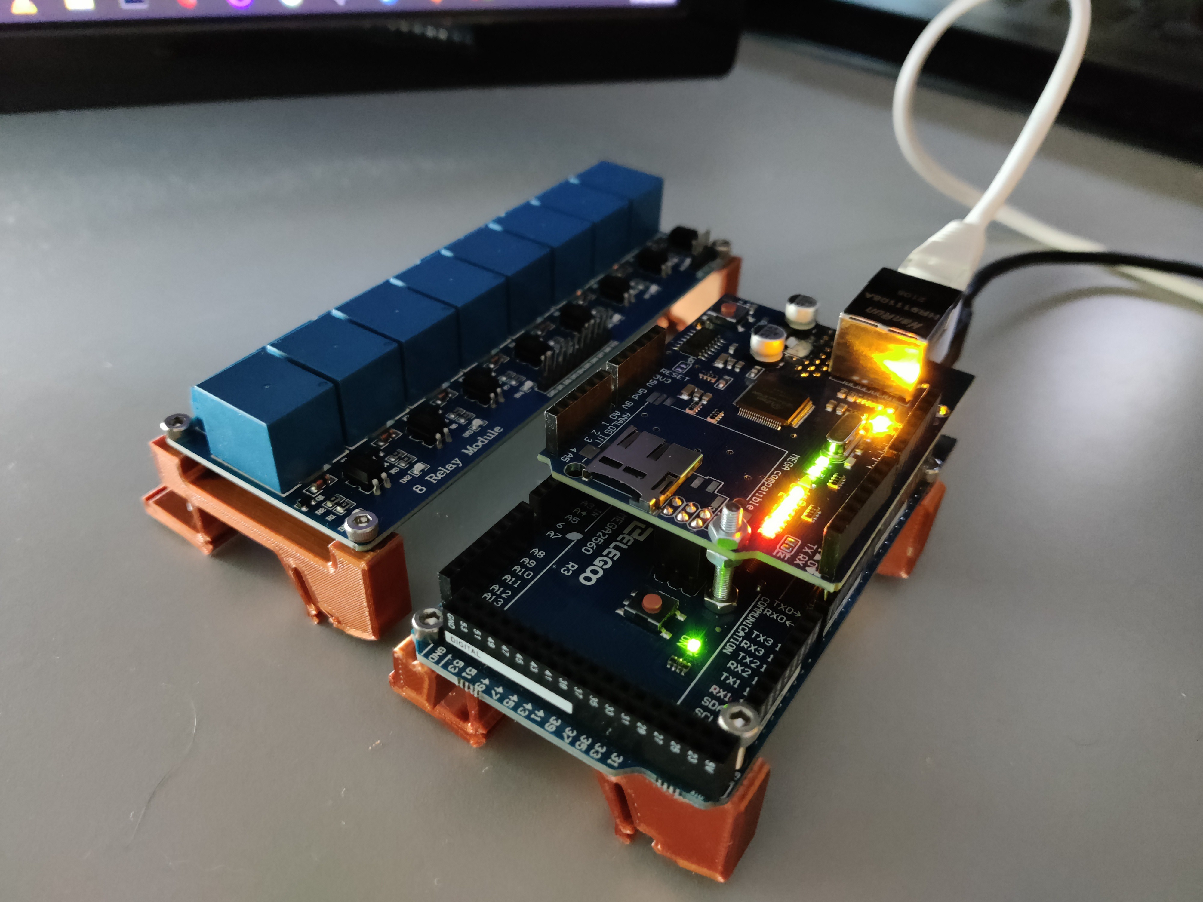
Finally, I am getting to build and test my new IO modules—all off-the-shelf parts except some small 3D-printed mounts.
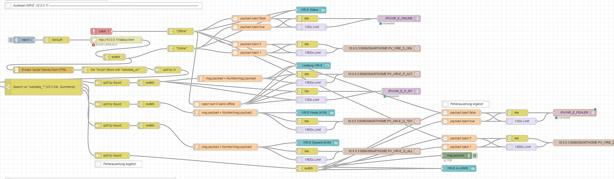
I recently installed a 4kWp PV-System ( 10 Panels connected to 5 Microinverters)
Naturally, I wanted to connect it all to my Smarthome. But the Modbus-TCP Interface of the Inverters (Deye SUN800) is not working for me. After browsing GitHub, I stumbled upon a solution (https://flows.nodered.org/flow/bf4e518f48eca5922ea3274680ac8692) to connect the web server of the inverter-data-logger. The web interface provides all necessary data like current power production, daily production, total production and fault codes. It works by logging into the web page via node-red and parsing the content for the needed data. After some filtering, the data is passed on to influx db (for grafana) and my smart home PLC via MQTT.
Now my smart home "knows" when "free" electricity is available and can switch on the car charger or the heat pump.
Since I have moved from a rental apartment to a house, it is possible to install some things I have long dreamed about.
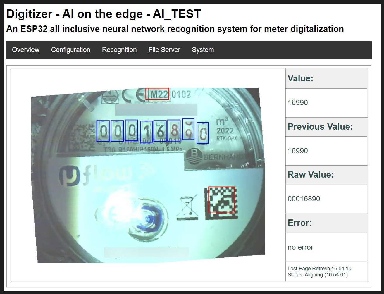
The first addition to my smart home system should be a real flow meter for the main water supply pipe. But while I was browsing the web for the cheapest flowmeter, I found a better solution. -To use the existing water meter and digitize it.
The AI-on-the-edge-device from jomjol on github https://github.com/jomjol/AI-on-the-edge-device is easy to implement and works flawlessly. The data is send via MQTT to my Nodered and Soft-plc...
The Web-UI:
My water usage from the last 7 days:
The 3d-printed enclosure is still missing some parts:
83 101 97 115 111 110 8217 115 32 71 114 101 101 116 105 110 103 115 33 32 72 111 112 101 32 121 111 117 32 97 108 108 32 101 110 100 32 116 104 101 32 121 101 97 114 32 111 110 32 97 32 98 114 105 103 104 116 32 110 111 116 101 32
Since there is now a real possibility that I am allowed to start building my own house (https://hackaday.io/project/169973-boxy-home) in 2022, it's time to think about a new version of my smart home project.
This time I start with the easy part -the GUI. I will keep the monochrome/highlights look.
Usually, I don't let go of a lot of my time to visual aspects of my projects. But the current situation gives me a bit more time to do some visual upgrades.
I printed a case for one of my Raspberry Pis, the one which runs Node-red and connects all of the third-party apps to my Software PLC and HMI.
The case is from Thingiverse: https://www.thingiverse.com/thing:3437219
To have not only a visual benefit i decided to add two status LEDs which are connected to GPIO Pins and can be controlled direct by Nodered.Currently the blue one gets lit on every status change of devices (light on/off) and the red LED is reserved for network or system errors.
Since I have connected my octoprint to my Nodered via MQTT a while ago, I wanted to do something with the data.
Smarthome page for printer controls.:
But i don't wanted to transmit all the Values via MQTT (the MQTT implementation in the PLC is a bit messy) to my Codesys RasPi PLC. So i decided to try the built-in OPC-UA Server.
View of OPC Nodes with the free Unified Automation UaExpert:
Now the Smarthome is able to tell when a print is finished and switch off the mains for the printer after the hotend is cooled down.
Part of SFC for the printer controls.:
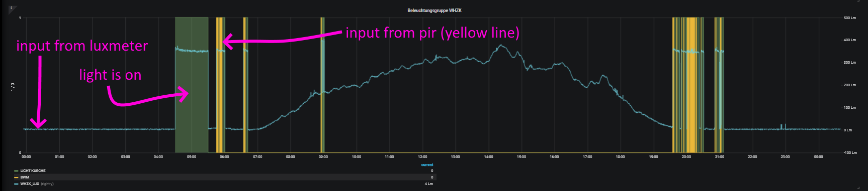
Some Grafana recordings of the in and output signals from my kitchen lighting.:
It starts with a model I found on Thingiverse. A cool case for an HC-SR501 motion sensor. (https://www.thingiverse.com/thing:3170870)
Since I had one of these lying around I wanted to add it to my smart home System.
The nearest I/Os to the preferred location are the digital inputs on the Pixtend Extension Board.
The only problem is that the HC-SR501 sensor outputs a 3.3V Signal and the DIs need at least 3.3V to flip high.
(https://www.pixtend.de/files/manuals/pixtend_technisches_datenblatt.pdf)
My solution should only involve components I had already in stock. So I decided to use a BC547 NPN transistor.
The signal gets inverted but that's no problem since I can negate the input in the PLC. I also mounted a lux meter (a photoresistor board with 0...2.5V output) in the motion sensor case. The boolean signal of the motion sensor and the analog value of the lux meter are processed from the PLC and the light gets switched on when needed.


I love the fact that my simple door switches started a discussion about retrocomputing. That's why i like the hackaday.io community so much.
@Ken Yap
I used this principle (well known technique for analog instruments): http://www.excelautomationsolutions.com/post/how-a-4-20ma-transmitter-works.html

Hi, your link to the Wikipedia SCADA page is broken, the text is correct, but the link is not. Also without knowing anything I suspected the 4..20 mA loop is an industry standard with such specific numbers, and it is, so maybe link to the Wikipedia page for that too? Thanks!

@Ken Yap -- the 4-20mA current loop scheme is very well known in the retrocomputing community... specifically the part that messes around with the, er, bigger machines. Minicomputers and such. See, before RS-232 (and, in some cases, even afterward) it was the best way to send a lot of serial data over a distance. Teletypewriters used this basically until the video terminal killed 'em all off.
You need four wires, two for TX, two for RX. Power and ground... and, no, you absolutely *cannot* combine grounds here. You're basically driving an optocoupler (or an open-collector junction, in the much older days) from a rather significant distance, for each side of the link... hence the values for the current there, and the fact that the voltage can vary so widely. IIRC it's active low, so a 'mark' ("1") is when the thing dips to 4mA and shuts off the little light in the opto, and a 'space' ("0") is when it levels back up to 20mA and the light comes back on ;)
The niftiest side of this, is that because it's /current/-dependent and basically screw the voltage as long as it can light a friggin LED or whatever, you can run these things quite nicely over insanely long distances (multiple /kilometers/, seriously... I want to say I heard that the signal really only peters out irretrievably at something like the 2km mark, but I could be off there... I could easily see it being longer, especially with repeaters) if you don't mind the transmission rate being kind of low... like 9600 baud maximum, and closer to 300 baud or so for the longer trips. (Baud?! Of course, dude, back then *everything* was baud. Screw BPS, we want to send things with character(s), not one friggin bit at a time :P )
...oh, and MIDI is basically exactly this, but with tighter voltage specs and a really freakin' weird baud rate.
Yeah it reminded me of the current loop teletypes we used to run that's why I looked it up.
I used to have a Decwriter LA30 which I converted from current loop to RS232, see here: https://hackaday.io/project/161656-flashing-leds-from-old-printer-electronics
Trivia Q: What was the name of the console teletype in the original PDP-11 Unix?
A: /dev/tty8
True story: When I was a neophyte in Unix, I asked the local sysadmin/guru how to detect machine shutdown, save state and exit my program gracefully. He told me to catch SIGTERM. After I mastered that I ran a small program in the background that just blocked waiting for SIGTERM. The next time the sysadmin shut down the machine, he saw the console print out Arrgh, you dirty rat... which was the code executed on receiving SIGTERM. In those days permissions were a bit lax and the console (by this time not a teletype) was world writable. I think they fixed the permissions after that.
Here's a bit more of Unix history I set down for posterity in my professional blog, which is mostly about things to do with my day job or my home Linux setup.
https://green-possum-today.blogspot.com/2018/09/the-true-origin-of-nuxi-problem.html
@Ken Yap LOL, I should've known you tinkered with that stuff /personally/ back in the day... you lucky bastard :P I've been fascinated with retrocomputing since probably when Mom got me a now-ancient copy of "The Soul of a New Machine" by Tracy Kidder. Still have it somewhere... awesome book.
Dangit, I need to read that thing again.
...also, why #8...? I'd expect 0 or 1 but not 8... actually, also, what were the other 7+ TTYs doing, if not running the console...? Logging stuff?
I don't remember, you could check the V6 history or Unix sources online but I think the first bank of minor devices, either didn't exist, or were allocated to other devices. I think more likely the former and the Unibus (DEC aficionados will remember this) slot for current loop serial devices was at 1.


 JanoHak
 GusGorman
 6toecat
SCADA is such an interesting branch of computing because they have techniques nobody else pays any attention to.
I've had a lot of success using my interpretation of tag point objects in Python, and I'm sure if I studied SCADA more I'd discover all kinds of stuff.