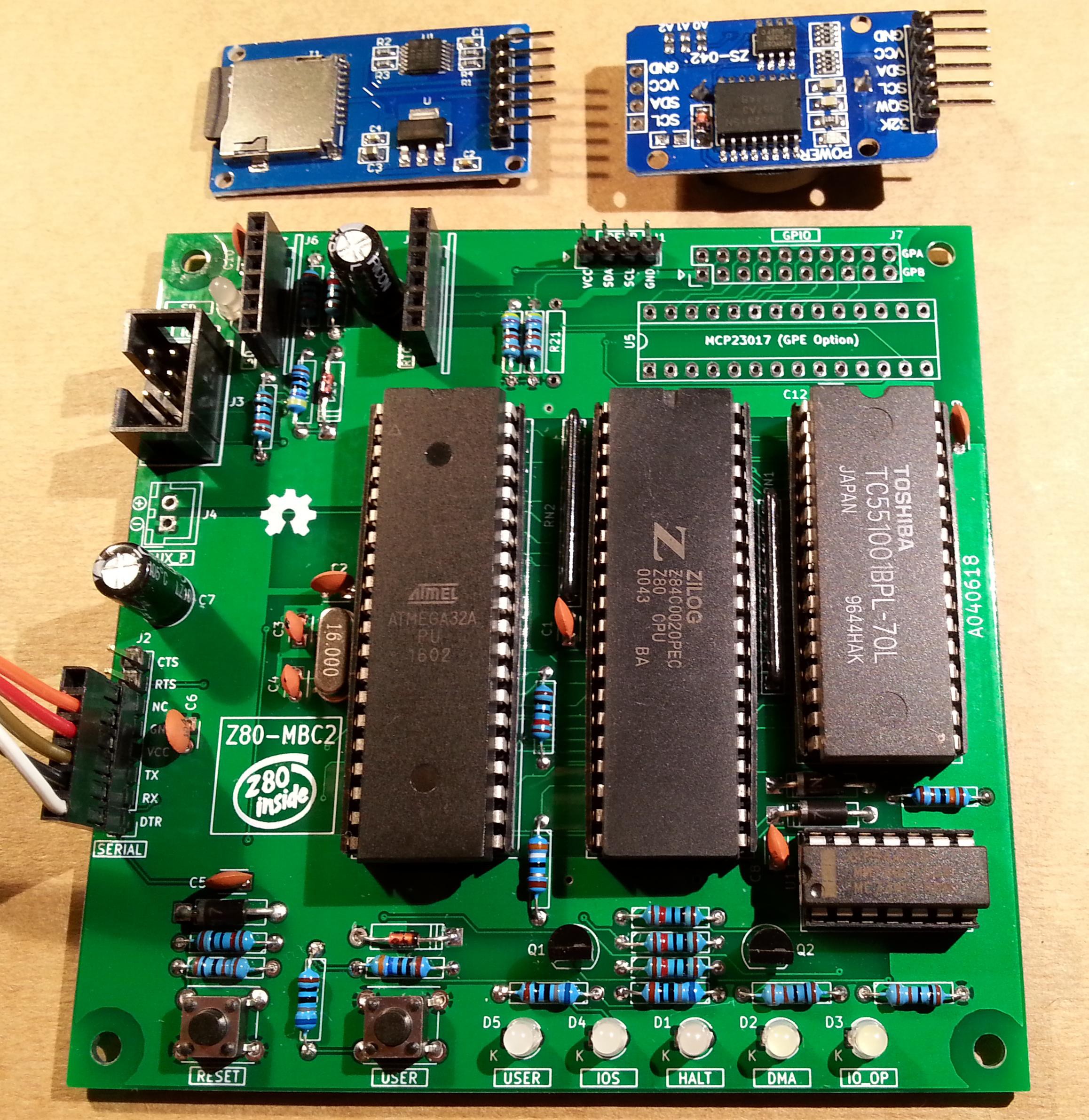
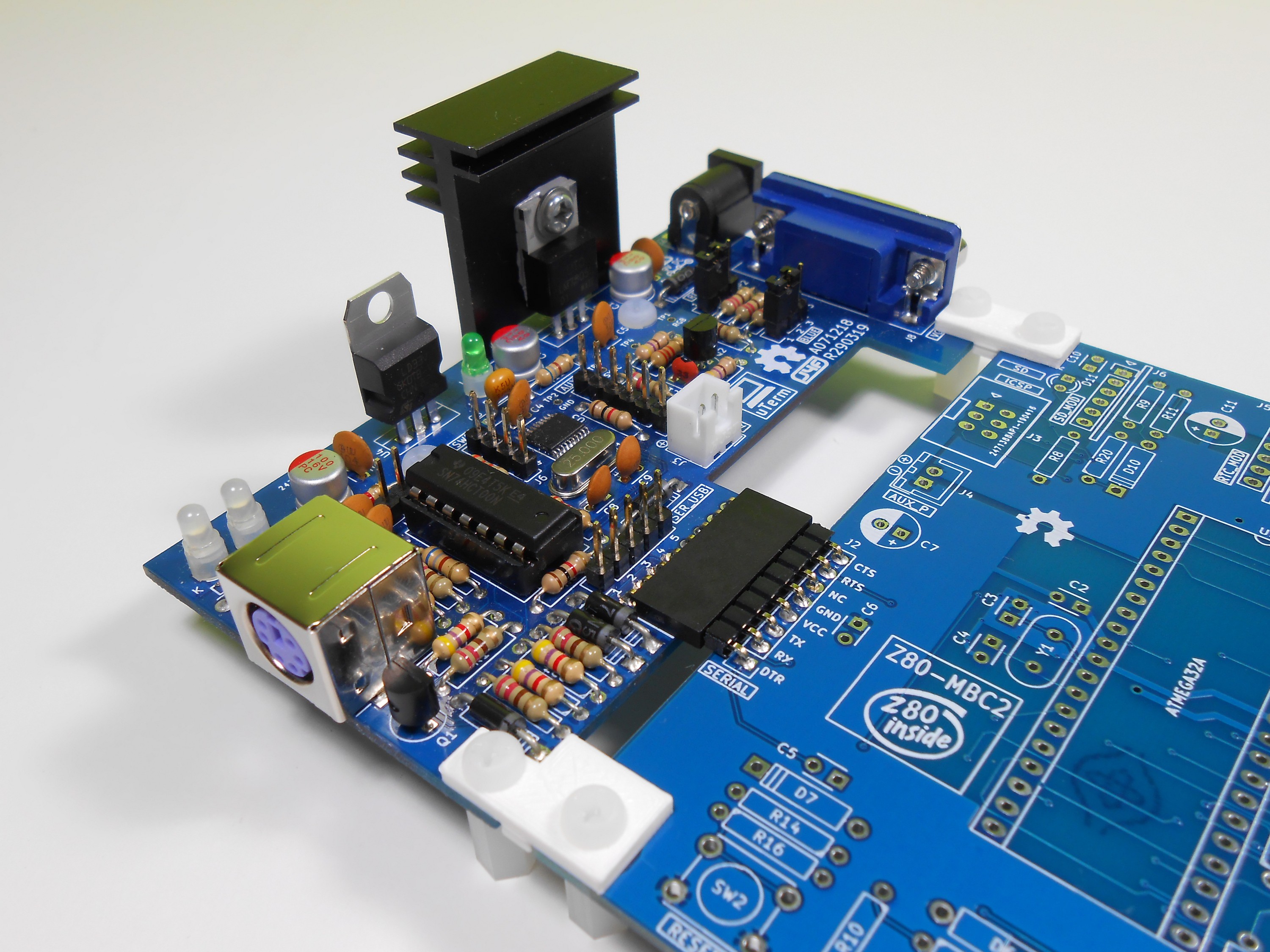
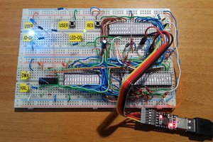
Close
0%
0%

Z80-MBC2: a 4 ICs homebrew Z80 computer

Homemade 8MHz Z80 SBC, 128kB banked RAM, RTC, SD (HD emulation), Basic and Forth interpreters, CP/M 2.2 and 3, cross Assembler and C (SDCC)

Similar projects worth following
The Z80-MBC2 is an easy to build Z80 SBC (Single Board Computer).It is the "evolution" of the Z80-MBC (https://hackaday.io/project/19000), with a SD as "disk emulator" and with a 128KB banked RAM for CP/M 3 (but it can run CP/M 2.2, QP/M 2.71, UCSD Pascal and Collapse OS too).

It has an optional on board 16x GPIO expander, and uses common cheap add-on modules for the SD and the RTC options. It has an "Arduino heart" using an Atmega32A as EEPROM and "universal" I/O emulator (so a "legacy" EPROM programmer is not needed).

It is a complete development "ecosystem", and using the iLoad boot mode it is possible cross-compile, load and execute on the target an Assembler or C program (using the SDCC compiler) with a single command (like in the Arduino IDE).


* * HARDWARE OVERVIEW * *

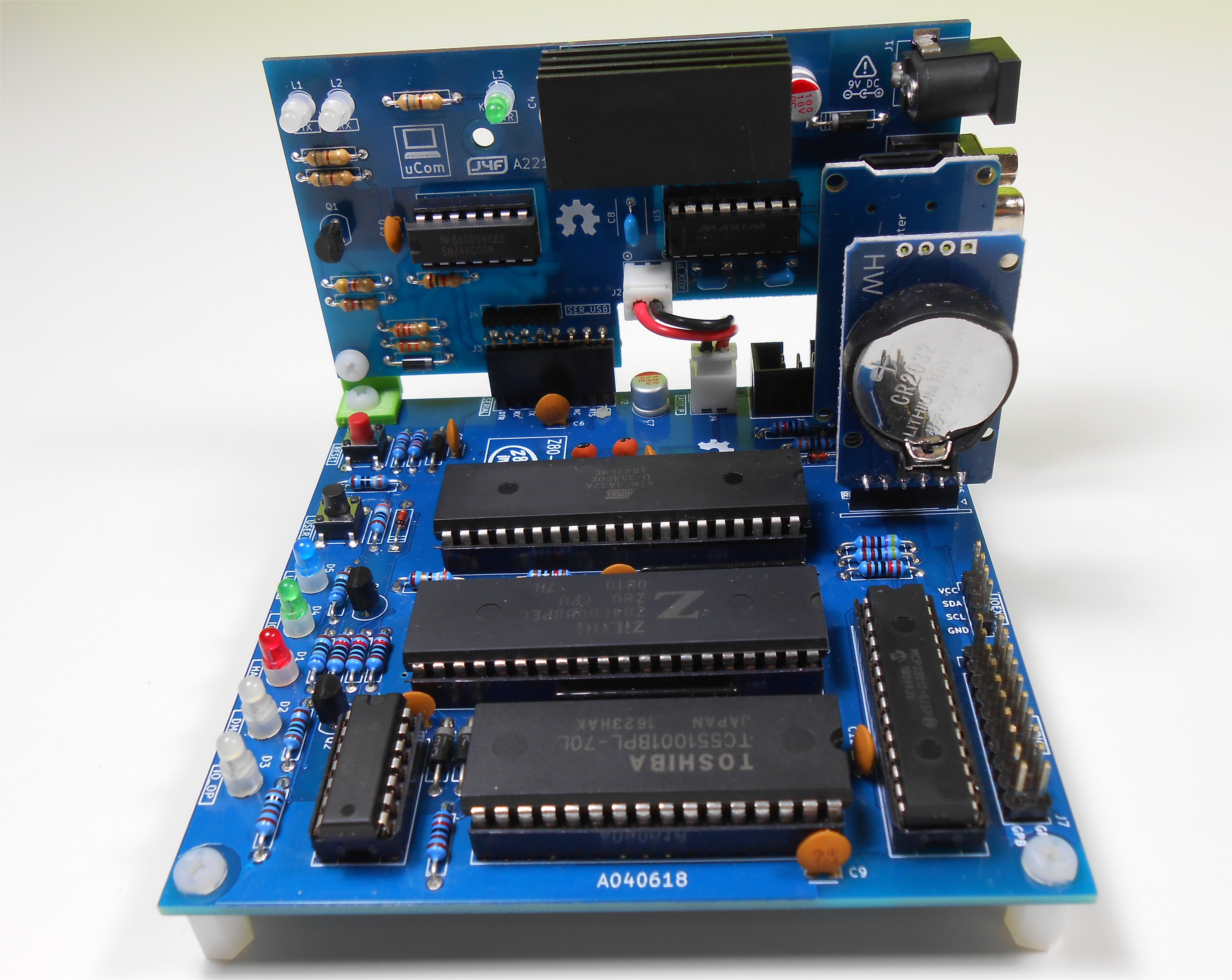
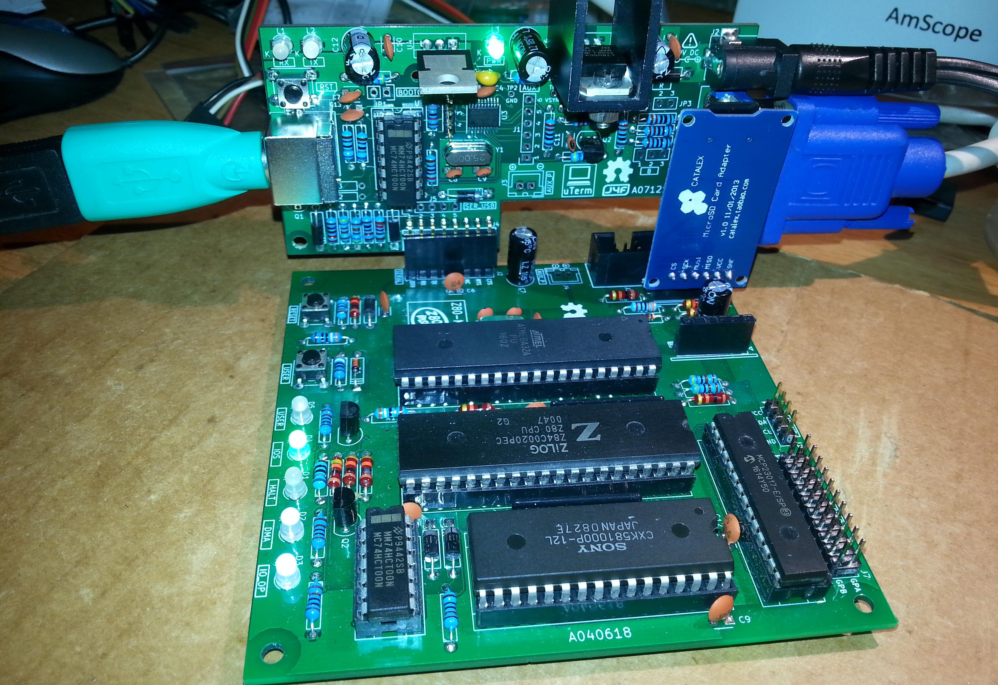
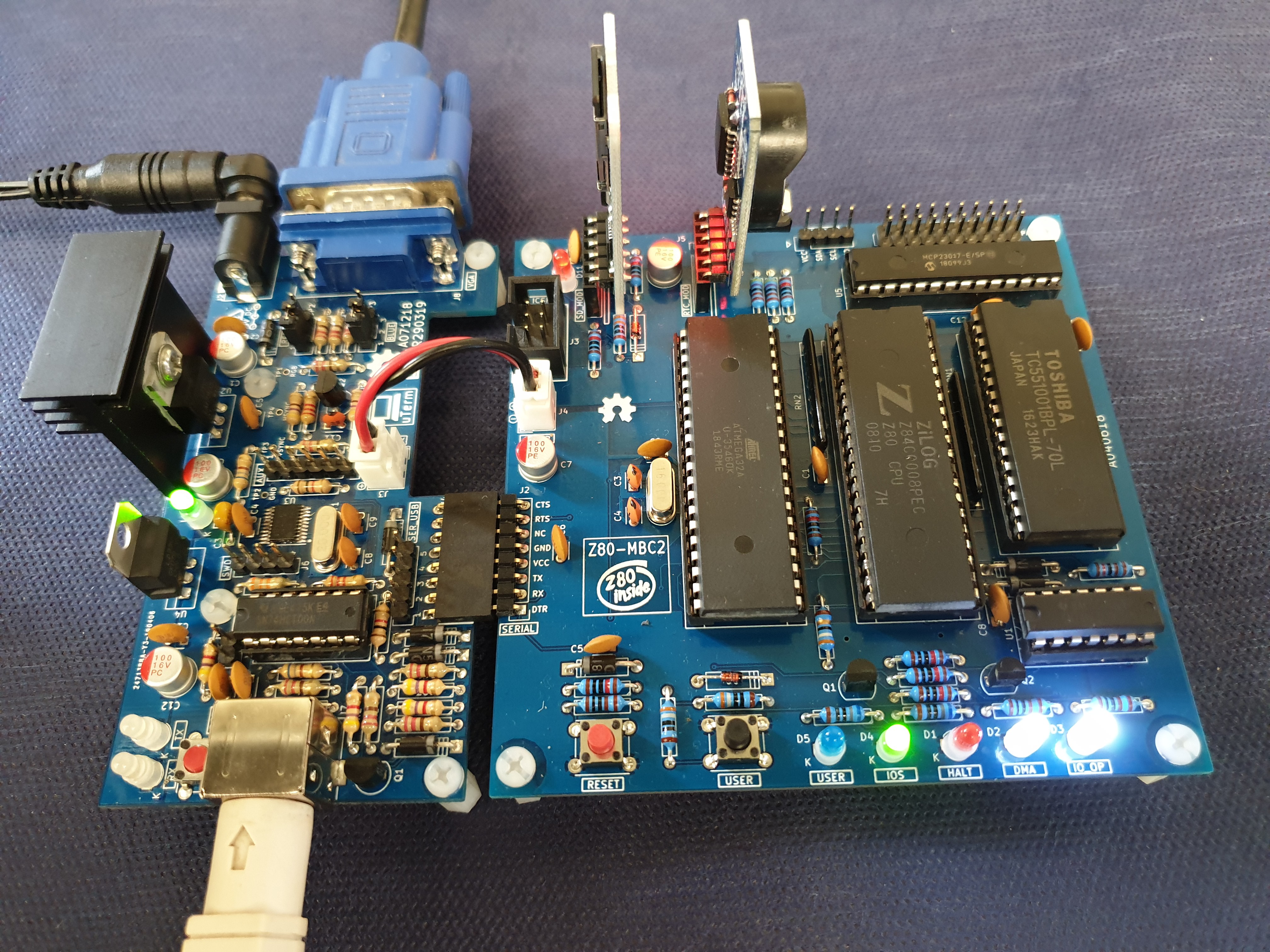
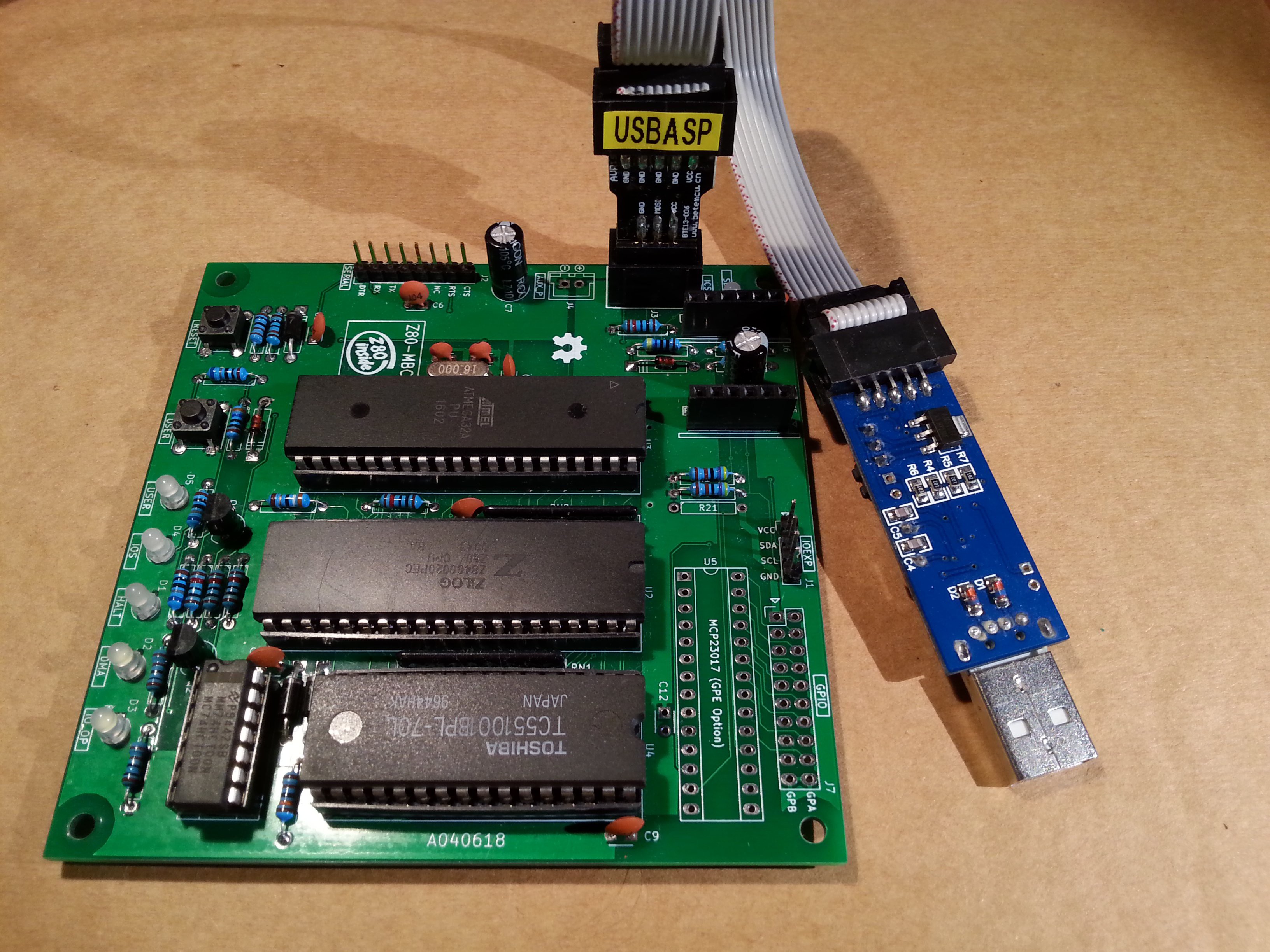
The needed ICs for the "base system" are:

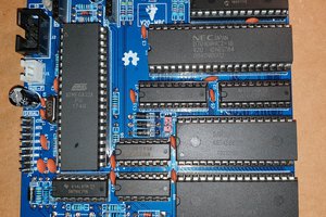
  • Z80 CPU CMOS (Z84C00) 8Mhz or greater
  • Atmega32A
  • TC551001-70 (128kB RAM)
  • 74HC00

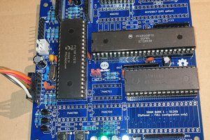
If you want the 16x GPIO expansion (GPE option) add a MCP23017 too.

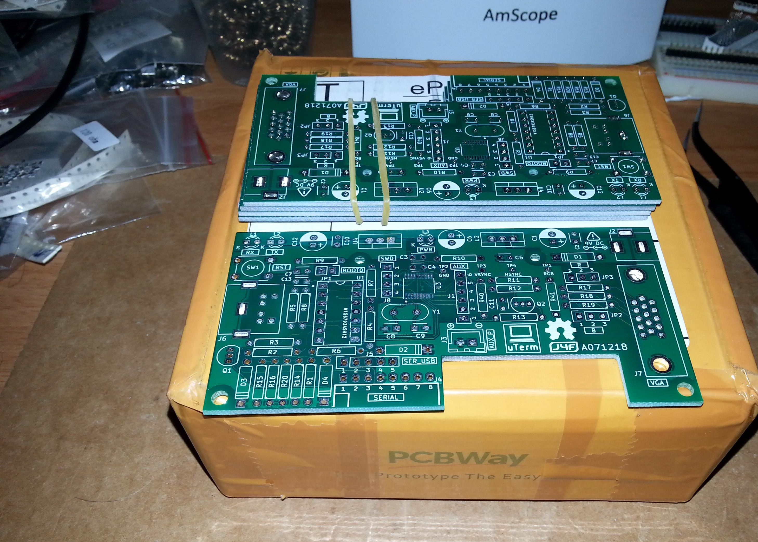
The schematic and the BOM are attached in the Files section. The MCU Atmega32A is used as universal I/O subsystem, as Eeprom, and as reset and 4/8MHz clock generator for the Z80 CPU.
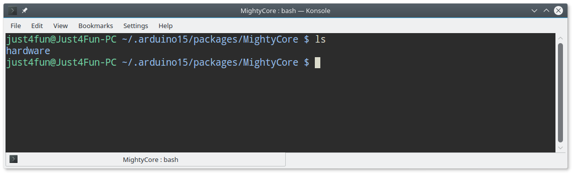
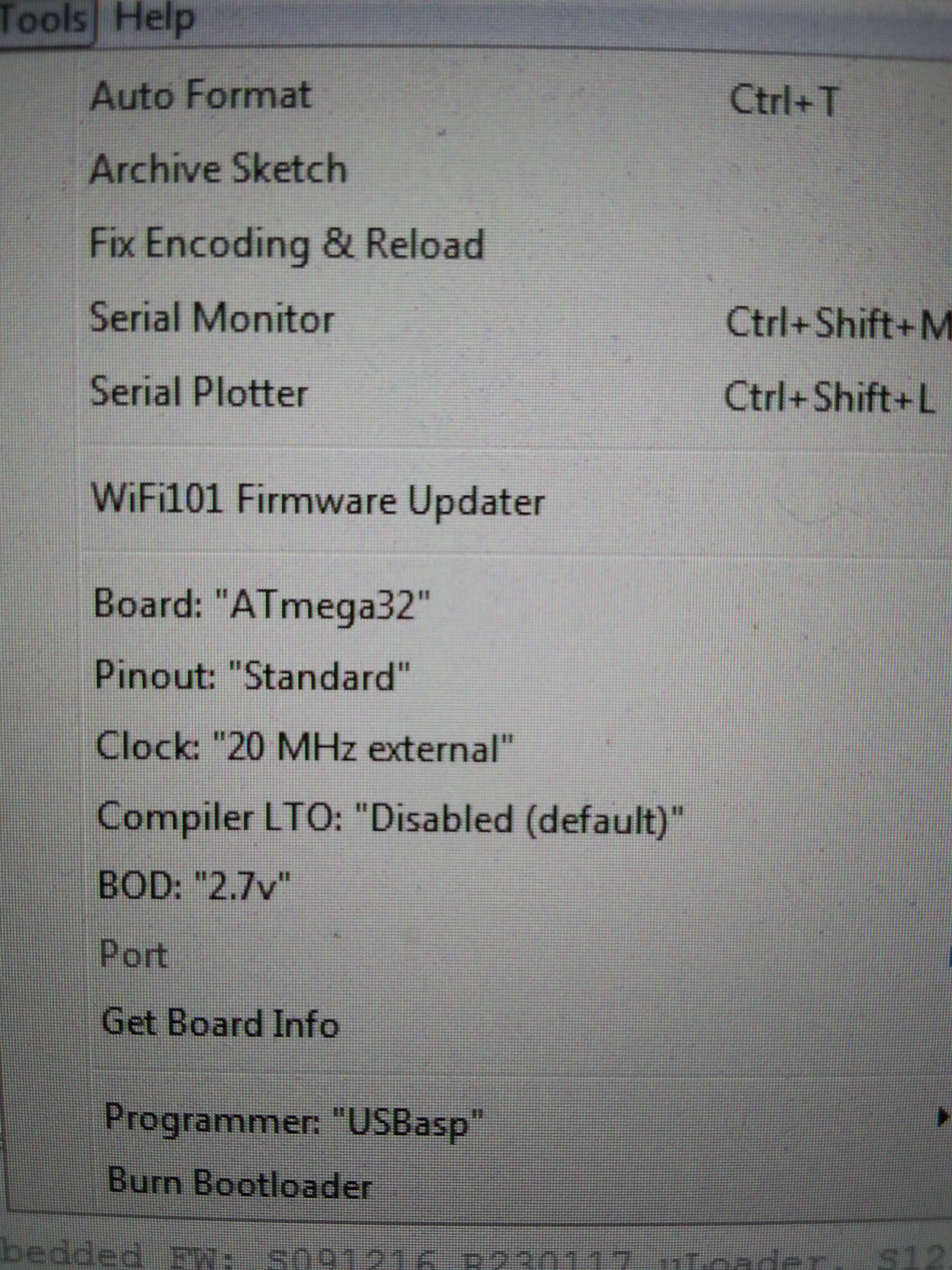
Inside the Atmega32A it is flashed an Arduino bootloader taken from here, and it is possible to use the Board Manager of the Arduino IDE to "import" it.

Flash the Arduino bootloader at first (with the method you prefer), next you can upload the IOS "sketch" (the I/O Subsystem that interacts with the Z80 bus and "virtualizes" the EEPROM and all the peripherals seen by the Z80 CPU) using Arduino IDE.

You can use the on board ICSP port J3 (also called ISP port) to write the bootloader, but remember to disconnect any other connector when using it. Also both SD and RTC modules (if present) must be removed from the board when the ICSP port is in use.

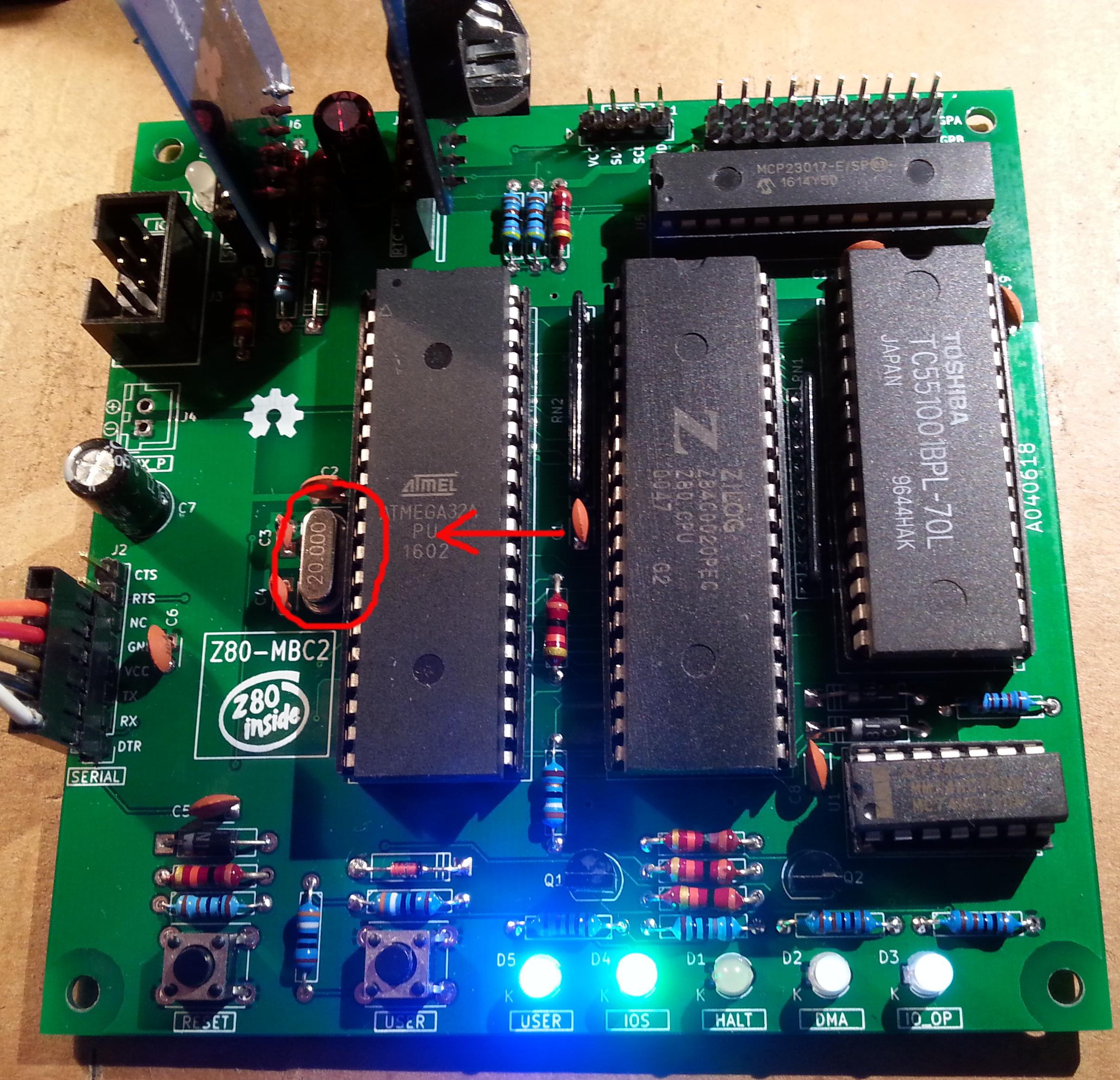
As clock source for the Z80 CPU it is used the 16MHz Atmega32A oscillator, so the "external 16MHZ osc." bootloader variant must be chosen when flashing the bootloader from the Arduino IDE!.

The 74HC00 is used as RS flipflop to stop the Z80 CPU during I/O operation, giving the needed time to the Atmega32A to interact with the Z80 bus, and as part of the MMU.

Note that only the CMOS version of the Z80 CPU can be used here. This because only CMOS version, under given condition that are respected in this schematic, has logical levels compatibles with Atmega32A and 74HC00.


NOTES ABOUT THE COMPONENTS

You should use a  Z80 CMOS speed grade of at least 8MHz for full speed, but setting the clock speed at 4MHz you can use a 4MHz Z80 CMOS version too (or you can try to overclock it at 8MHz...). The 74HC00 can be substituted with a 74HCT00 if you already have one. The RAM chip TC551001-70 can be substituted with any suitable 128kB SRAM).

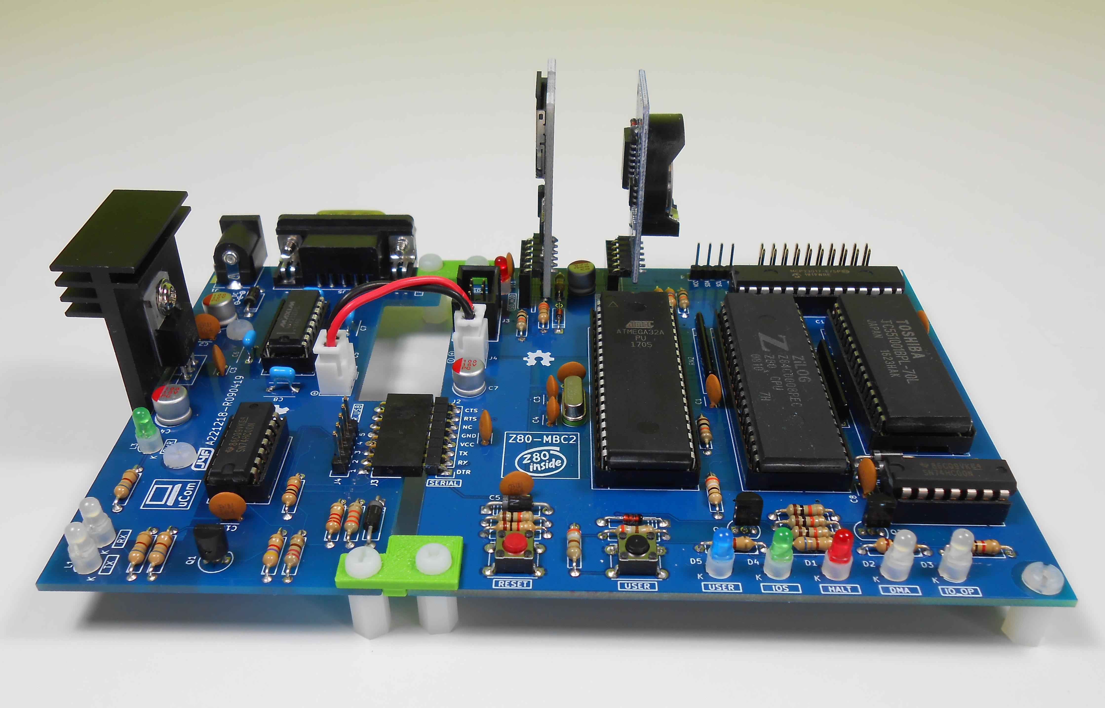
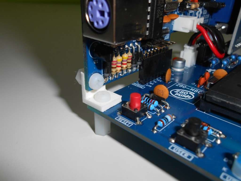
Please note that the USER led  * must * be blue or white (or pink... I've some pink leds that seems to have a Vf like blue one. May be I'll do a board with them...) just to be sure that V(forward) is >= 2.7V (otherwise the USER key may not work as expected).

The J4 connector (AUX_P) is not currently supported and is not populated by default.

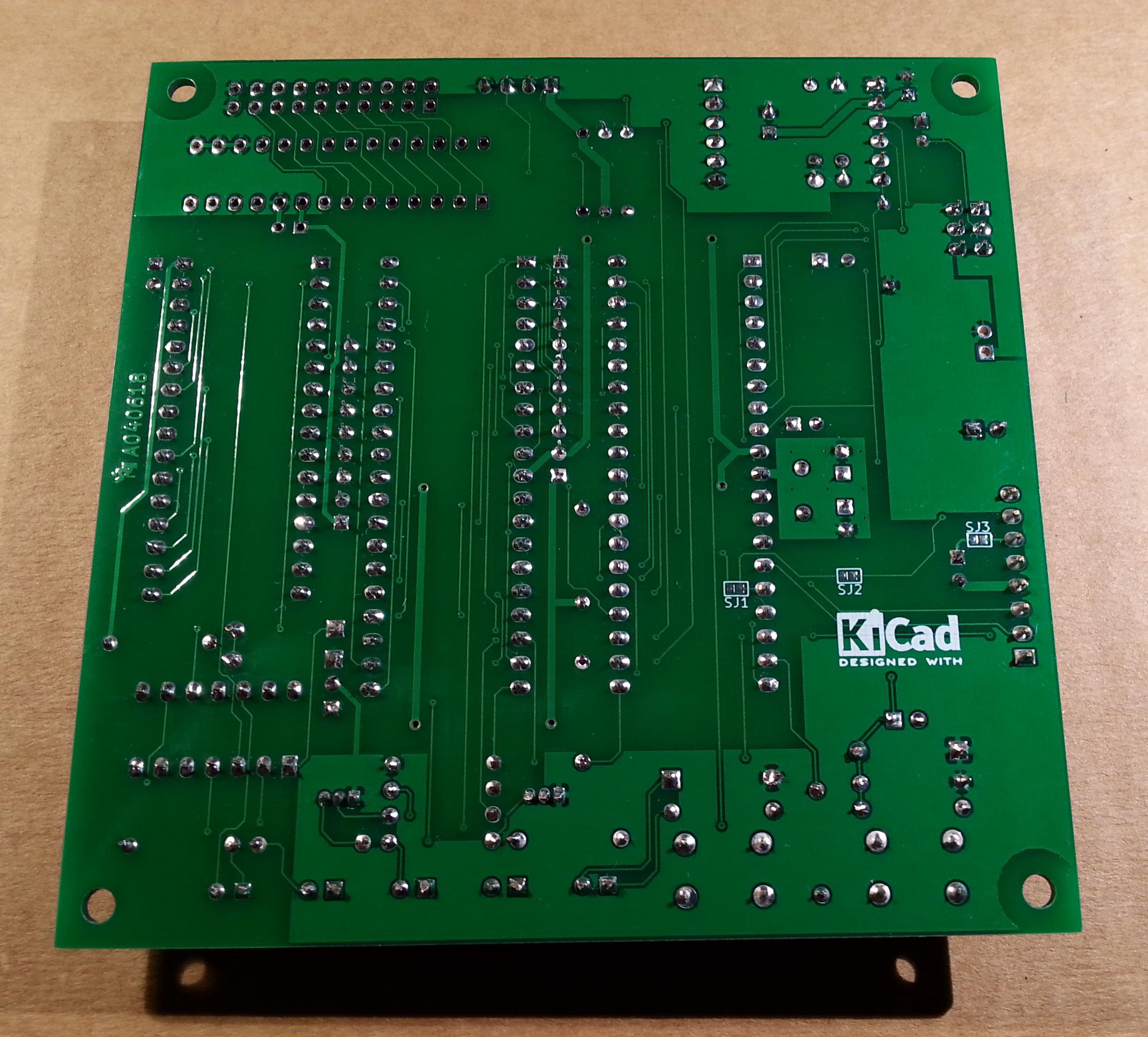
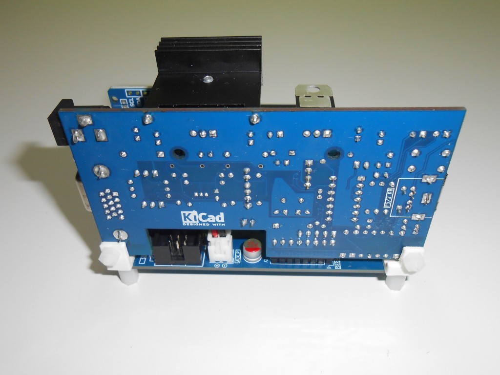
The three solder jumpers (SJ1-3) on the bottom side are not currently supported and must  be left opened (as stated in the schematic).
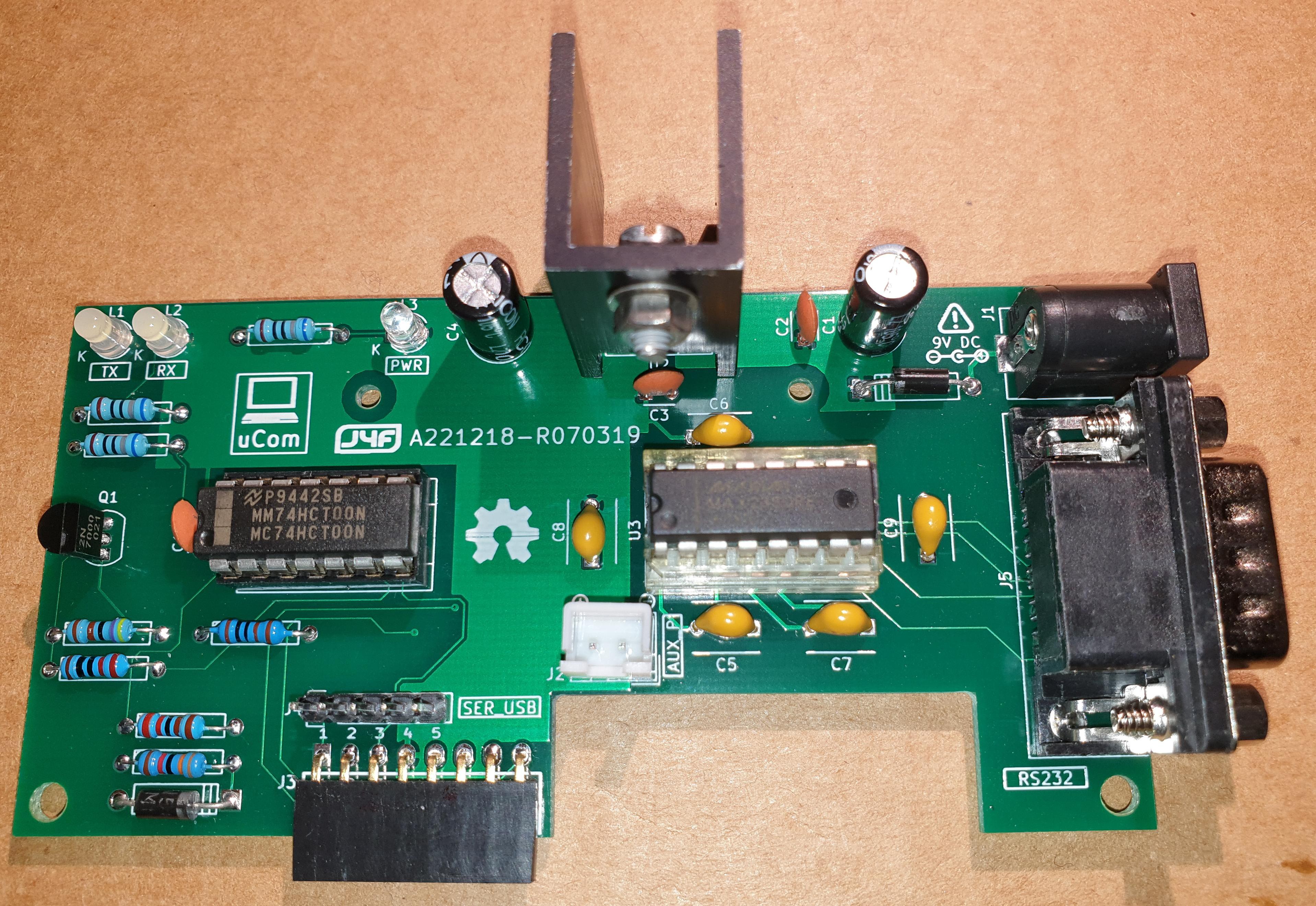

THE SERIAL PORT

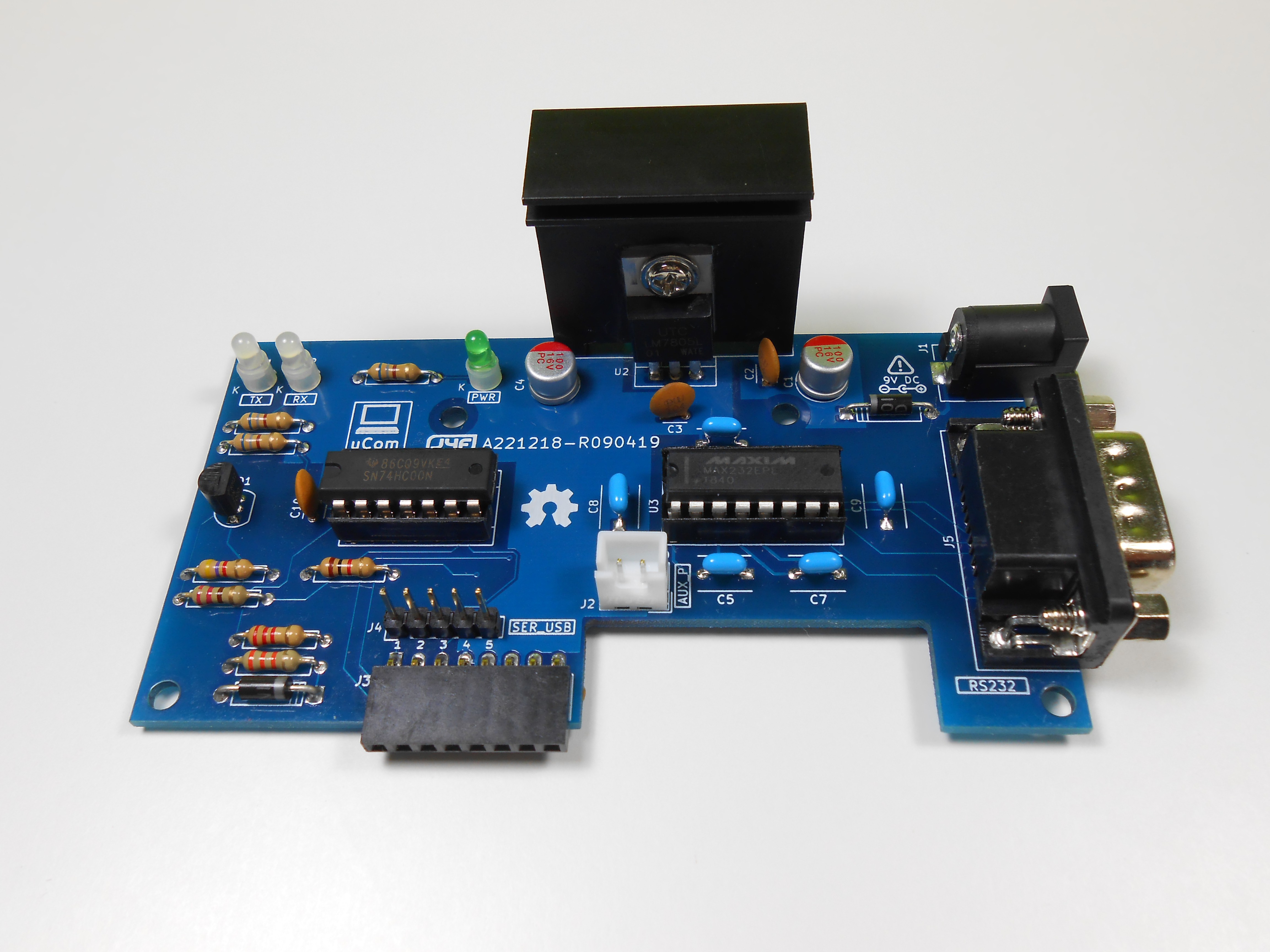
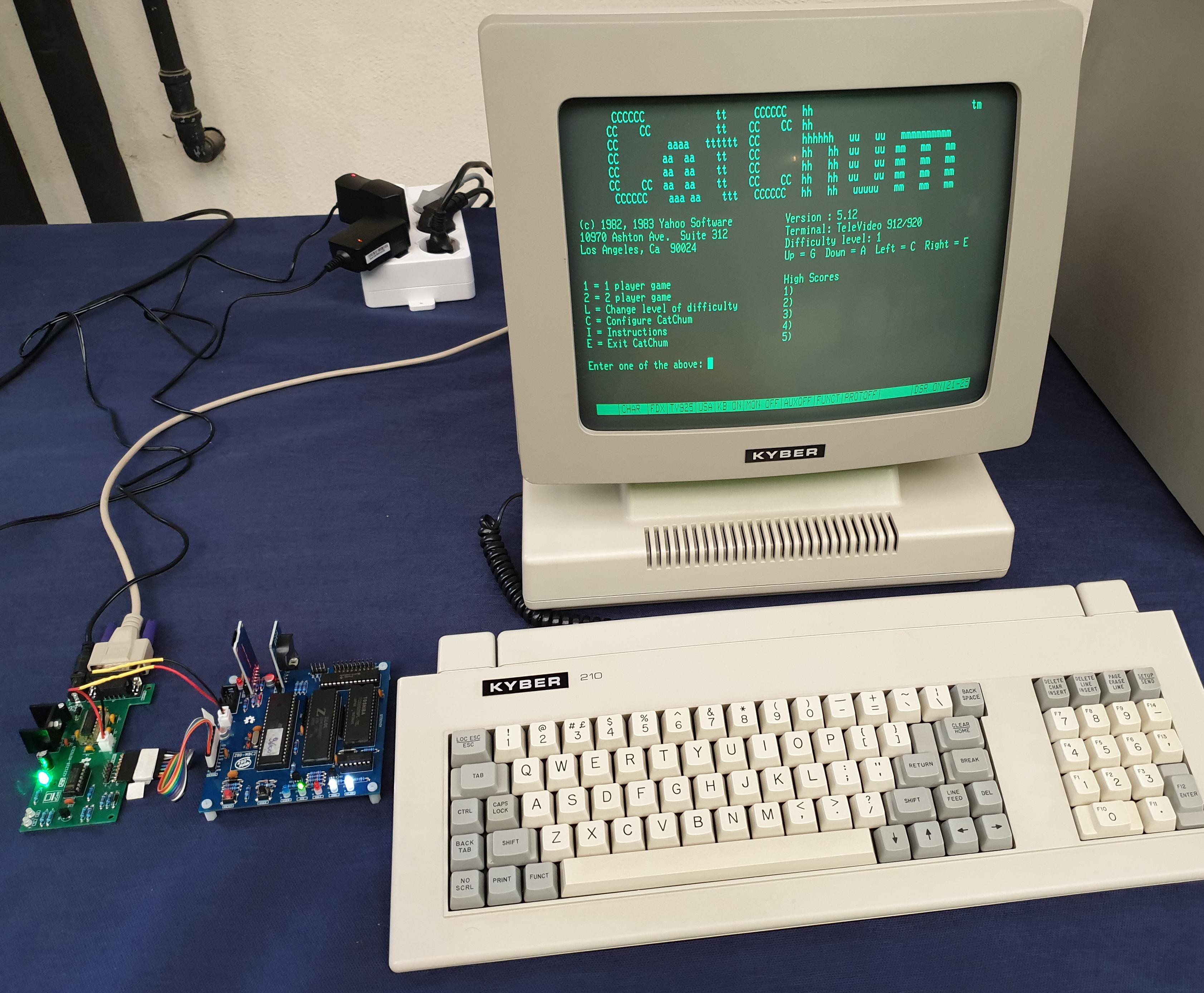
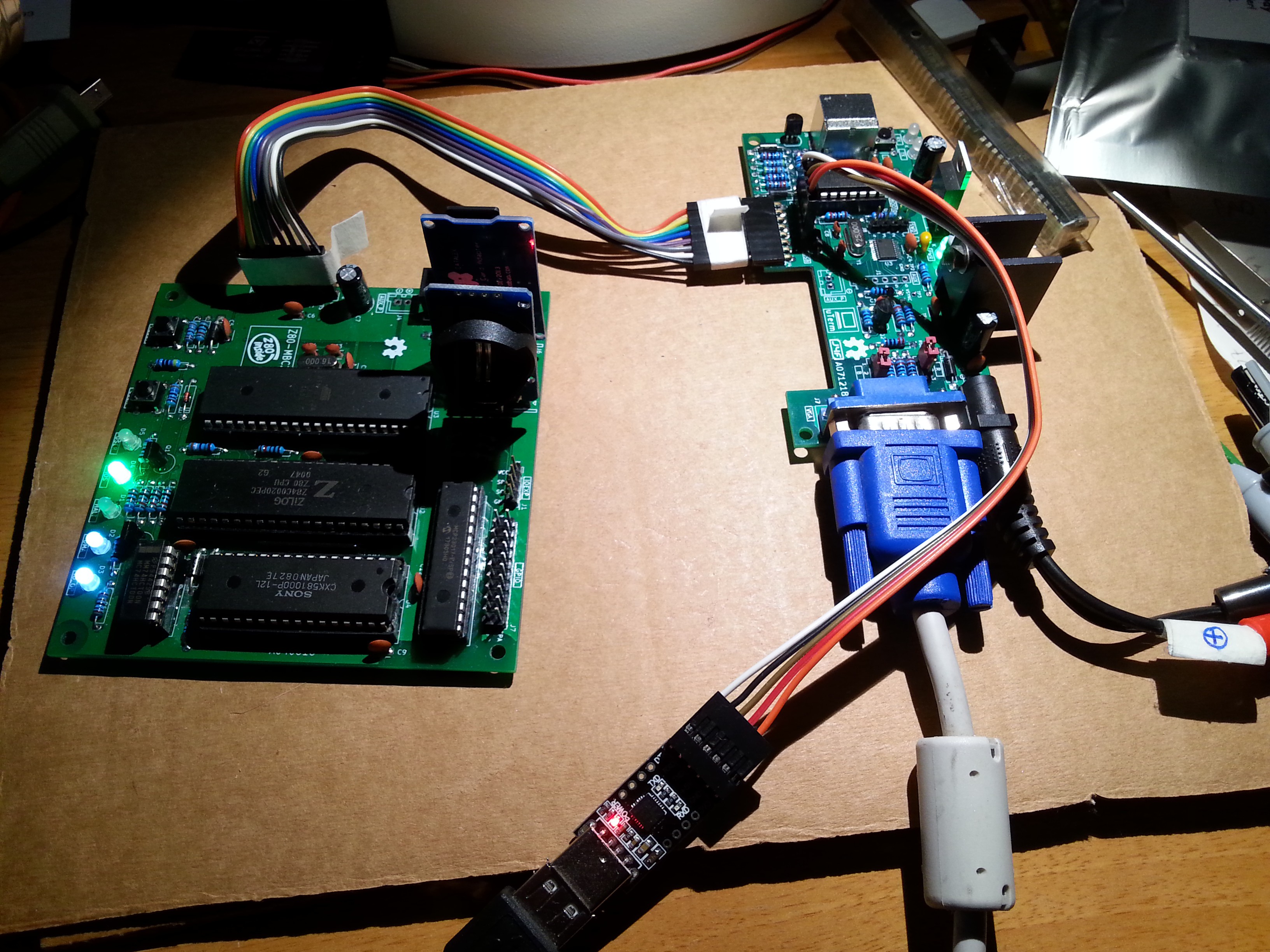
The  SERIAL port (J2, see schematic) can be connected with a TTL-RS232 adapter, or with a serial-USB adapter.
I've used a serial-USB adapter that acts also as power source for the Z80-MBC, and has the DTR signal for the "autoreset" driven from the Arduino IDE. For a terminal that has a serial TTL port no adapter is needed.

Of course to upload a "sketch" from Arduino IDE you need to use a serial-USB adapter connected to the SERIAL port.

Note that the RTS and CTS pins of the SERIAL port are not currently supported and must be left not connected (as the NC pin!).

The 3V3 pin of the serial-USB adapter must be left disconnected  (if present).

You should use those Serial-USB adapters that have the DTR pin on the connector. It is suggested to have also the CTS/RTS signals available for future upgrades.

Please note that all the pin names of J2 on the PCB are referred to the serial-USB adapter, so all the signals as TX and RX are relative to the serial-USB adapter side (in other words TX and RX are already "inverted". See the schematic).

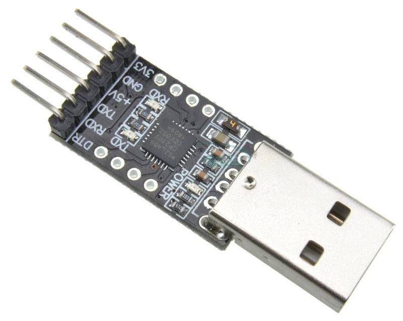
Here a suggested serial-USB adapter based on a CP2102 (very common on ebay):


THE OPTIONAL RTC MODULE

The RTC is a common module based on a DS3231  RTC  like this one:

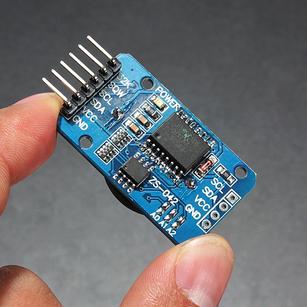
This cheap modules have a trickle charging circuit that may cause the "explosion" of the battery if you use a standard CR2032 cell. More, it can damage also a rechargeable LIR2032...

Read more »

SD-S220718-R240620-v1.zip

The content of the microSD needed to run CP/M 2.2, CP/M 3.0, QP/M 2.71, UCSD Pascal and Collapse OS with IOS S220718-R240620. Adds Collapse OS.

Zip Archive - 3.69 MB - 06/25/2020 at 10:41

Download

S220718-R240620_IOS-Z80-MBC2.zip

The sketch for the IOS (with the needed libraries). Unzip into a folder and open the .ino file (with Arduino IDE). IOS must be uploaded into the Atmega32A flash. Adds support for Collapse OS.

Zip Archive - 37.34 kB - 06/25/2020 at 10:40

Download

S220718-R240620_IOS-Z80-MBC2.ino.with_bootloader_atmega32_16000000L.hex

The sketch for the IOS in executable format (.HEX) with the bootloader. This executable file is intended for use with a programmer as the Atmel Ice or AVRISPmkII or others (Fuse bits: High Byte 0xD6, Low Byte 0xAF, Lock Byte 0xCF)

x-hex - 55.76 kB - 06/25/2020 at 10:39

Download

STARTREKV2.BAS

The famous game Super Startrek kindly debugged by a RetroBrew Computer Forum user. Play with Caps-Lock activated! Now the animation works...

bas - 20.18 kB - 08/07/2018 at 16:32

Download

TREKINST.BAS

Instructions for STARTREKV2.BAS

bas - 6.80 kB - 08/04/2018 at 21:48

Download

View all 11 files

  • 1 × See the file "A040618 BOM v2.ods" in the FILES section.

  • Collapse OS on the Z80-MBC2!

    Just4Fun06/25/2020 at 10:54 0 comments

    Collapse OS is now supported on the Z80-MBC2:


    Update both the IOS firmware and the SD image.
    For more info the Collapse OS site is here.

  • UCSD Pascal for the Z80-MBC2!

    Just4Fun09/01/2019 at 15:45 3 comments

    Thanks to Michel Bernard (a member of the Z80-MBC2 User Group on FB) who did the porting, now UCSD Pascal is running on the Z80-MBC2!

    Michel Bernard originally used the trick to create a custom autoboot.bin file to be used with the "Autoboot" boot selection to load the OS.

    Because this porting is so cool, I've done a new IOS version and a new SD image to support UCSD Pascal in the same way as the others previous OS, adding a new "Disk Set" selection:


    To run UCSD Pascal you just need to update the new IOS and the new SD image (in the Files section) and select it from the usual "Select boot mode or system parameter" menu:


    In the new SD image there are two volumes (disks) SYS1: and SYS2:


    Here the execution of an example (SINE.CODE) already compiled on the SYS2: disk:


    In the folder "UCSD Pascal" inside the SD there are the original files and sources provided by Michel Bernard.
    A lot of documentation and books about UCSD Pascal can be found here.

  • uCom is out!

    Just4Fun05/29/2019 at 09:20 0 comments

    I've done a separate "project page" for uCom (RS232 add-on card for the Z80-MBC2) here.

    The uCom board, as the uTerm VT100 board, has a "transparent" USB-serial adapter connector, so you can upload firmware to the Z80-MBC2 (using Arduino IDE) or load an Intel-Hex file (with iLoad) or use XMODEM to exchange files with a PC (running a terminal emulator that supports XMODEM file transfer) while the uCom is in use.

    Both the "mixed" power supply scenarios (USB-serial adapter not powered from USB but Z80-MBC2 powered and vice-versa) are managed by the HW, so you don't need to worry about it.

    uCorm can be mounted horizontally or vertically to the Z80-MBC2.

    The 3D printed custom angled brackets .STL files are the same of the uTerm.


    Here connected with a "vintage" RS232 terminal (Ampex 210 relabeled Kyber):

  • FuzixOS preview: Unix for Z80!...

    Just4Fun05/21/2019 at 17:14 4 comments

    First test with FuzixOS on the Z80-MBC2 (many many thanks to Alan Cox...)!:

    Stay tuned...

  • uTerm is out!

    Just4Fun05/14/2019 at 07:40 0 comments

    I've done a separate "project page" for uTerm here.

    uTerm can be mounted horizontally or vertically to the Z80-MBC2.

    All the details including the 3D printed custom angled brackets .STL files are there.

    uTerm is a VT100 terminal with VGA out and  PS/2 keyboard with a power supply (for the Z80-MBC2 too). It has a "transparent" USB-TTL adapter connector, so you can upload firmware or load an Intel-Hex file (with iLoad) while the card is inserted. Both the "mixed" power supply scenarios (USB-TTL adapter not powered from USB but Z80-MBC2 powered and vice-versa) are managed. The video terminal is based on the ChibiTerm (https://hw-by-design.blogspot.com/2018/07/low-cost-vga-terminal-module-project.html).


  • uCom preview: a RS232 adapter for the Z80-MBC2...

    Just4Fun04/05/2019 at 17:00 0 comments

    Currently working on a RS232 add-on card for the Z80-MBC2.

    As the uTerm board, it has a power supply for the Z80-MBC2 and a "transparent" USB-TTL adapter connector, so you can upload firmware or load an Intel-Hex file (with iLoad) while the card is inserted. Both the "mixed" power supply scenarios (USB-TTL adapter not powered from USB but Z80-MBC2 powered and vice-versa) are managed.


    Here connected to an Ampex 210 terminal (sold and relabeled by Kyber):


    Stay tuned...

  • New IOS for XMODEM support

    Just4Fun03/10/2019 at 10:54 6 comments

    Because some people requested to use the XMODEM protocol to exchange files through the serial port, I've added the support for this protocol into CP/M 2.2 and CP/M 3 (banked only).

    XMODEM needs a full 8 bit binary data transfer, and this is not possible with the CON port (the CP/M port used for the console) with a "legacy" CP/M system installation because the CP/M Alteration Guide says to strip the eight parity bit when reading a byte from the console input.

    More, because the Z80-MBC2 uses a virtual serial port without handshaking there is also a timing problem when dealing with the 128 bytes packets used by the XMODEM protocol.

    So the support to the XMODEM protocol has requested changes in the IOS and  in the CP/M BIOS, and also in the Arduino core to extend the serial input buffer.

    Please note that with the new IOS the default speed of the serial port is now 115200 bps.

    To have the XMODEM support active, before the update of the new IOS firmware and the new SD image (see in the Files section),  you have to manually create a new "board variant" in the Arduino IDE and then change the default Rx input buffer size to 128 bytes in the "core" of this new variant.

    If you aren't interested into the XMODEM support, you can simply update the IOS and the new SD image as usual  without the need to create the new board variant. In this case the XMODEM will not work in the receive direction, but only in the send direction (from the Z80-MBC2 to a PC with a terminal emulator).


    HOW MANUALLY CREATE A NEW BOARD VARIANT (LINUX)

    In the following I'll assume an Arduino IDE 1.8.5 installation on a linux host and the MightyCore ver. 1.0.8. Anyway I've tried to make the procedure enough general to be used for other versions too.

    The first thing is find the directory where the MightyCore is located.

    If you have installed Arduino IDE 1.8.5 and then installed the MighyCore with the Board Manager with the usual .json "pointer", the MightyCore is located in the "~/.arduino15/packages/MightyCore" directory:

    Now you must locate the "~/.arduino15/packages/MightyCore/hardware/avr/1.0.8/cores" directory (note that the "1.0.8" part of the directory name depends on the MightyCore version, and so can be a different number if you have a different version of the MighyCore):

    ... Read more »

  • uTerm preview: a VT100 terminal for the Z80-MBC2...

    Just4Fun12/28/2018 at 10:16 2 comments

    Currently working on a VT100 terminal with VGA out and  PS/2 keyboard with a power supply (for the Z80-MBC2 too). It has a "transparent" USB-TTL adapter connector, so you can upload firmware or load an Intel-Hex file (with iLoad) while the card is inserted. Both the "mixed" power supply scenarios (USB-TTL adapter not powered from USB but Z80-MBC2 powered and vice-versa) are managed. The video terminal is based on the ChibiTerm (https://hw-by-design.blogspot.com/2018/07/low-cost-vga-terminal-module-project.html).

    Stay tuned...


    Working on a new revision (A071218-R250119):


    Waiting the new PCB, I'm playing with the current PCB "patched" to perform like the new one.
    Here a session with Wordstar 4 configured to use all the 30 rows of uTerm:

    In the photo you can see that also the serial-USB adapter is attached to the uTerm using the "transparent" port. This allows to use two keyboards and two monitors in the "same" time (one keyb and monitor attached directly to the uTerm, and another keyb and monitor of the terminal emulator on a PC connected with the serial-USB). This allows also to use XMODEM (e.g. between the Z80-MBC2 and a PC) or to flash the Atmega firmware with the uTerm connected.

    Or you can use the monitor attached to the uTerm and the keyboard of the terminal emulator on a PC. This is exactly the "configuration" I used in the photo to make the test (as you can see, there isn't any keyb attached to the uTerm).


    Catchum demo with uTerm (a sort of Pacman...). Leaving the game alone, after a while the "demo mode" starts:

    Here last version assembled horizontally with the Z80-MBC2:


    Currently making custom 3D printed mounting brackets for a solid vertical assembling:

  • Overclocking the Z80-MBC2...

    Just4Fun11/02/2018 at 09:51 4 comments

    Because the Mighty Core gives the chance to choice a 20MHz bootloader, I've decided to try to "overclock" the Atmega32A using a 20MHz quartz:

    You don't need others HW changes, just use a 20MHz quartz instead of a 16MHz one. The Z80 clock speed will be at 10MHz.

    You have to select the "20MHz external" option in the "Toos" menu of Arduino IDE before flashing the 20MHz bootloader:


    Of course you need to load the sketch again (using the "20MHz external" option). IOS will display the new clock speed:


    Remember that using a 20MHz quartz you are out of the Atmega32a specifications (the Atmega32a is rated at 16MHz max.), so you are in a "grey area" where things "may works"...

  • CP/M 3 up and running on the Z80-MBC2!

    Just4Fun10/11/2018 at 06:58 0 comments

    With the latest IOS revision and the corresponding new SD image (see the Files section) there is one more option: the CP/M 3.0!

    With CP/M 3.0 it is possible use the 128KB banked RAM to have a wider user area (TPA) for programs and a more "evoluted" OS.


    TWO VERSIONS

    Just as example of how it is easy with CP/M 3.0 manage multiple configurations, I've done also a "non-banked" 64KB version. The switch from one version to the other can be done simply running a batch from the console itself.

    I've prepared two simple batch files to do that. From drive A: the command:

    submit sys64

    will set the 64KB "non-banked" version and then reboot the system.

    To activate again the 128KB "banked" version give the command (from drive A:):

    submit sys128

    NEW DISKDEFS FILE

    To use cpmtools or cpmtoolsGUI with the virtual disks of the CP/M 3.0 environment, you must update the DISKDEFS definition file (from the SD in the folder <SD>/cpmtools/) and use the "z80mbc2-cpm3" entry for all the 16 disks:

    Please note that for the CP/M 3.0 environment all the 16 virtual disks have the same structure and for this there is only one entry for all the CP/M 3.0 virtual disks.


    AUTOEXEC

    The AUTOEXEC switch for CP/M 3.0 works in a different way from the CP/M 2.2 and QP/M 2.71 implementations.

    Now there is a custom utility (AUTOEXEC) that checks the IOS flag and sets the exit code accordingly (using the BDOS function 108). This allow to use the CP/M 3.0 batch conditional execution (see the CP/M 3 Programmer Guide par. 1.6.3) to run any wanted command or program based on the status of the IOS AUTOEXEC flag.

    I've prepared an example using an other CP/M 3.0 feature, the "PROFILE.SUB" batch that is automatically executed at cold boot (if it exists). To activate it (in the drive A:) rename the file PROFILE.SU as PROFILE.SUB with the command:

    ren profile.sub=profile.su

    Now you can see how it works setting the AUTOEXEC flag on or off with the IOS "Select boot mode or system parameters" menu.

View all 13 project logs

Enjoy this project?

Share

Discussions

JoeH wrote 08/18/2023 at 19:48 point

Does anyone know if the ATMega32 can be reprogrammed (sketch not bootloader) while still in circuit using the Z80-MBC2 serial port? I want to update my firmware to the latest version. Thanks.

  Are you sure? yes | no

Just4Fun wrote 09/13/2023 at 08:26 point

In your case you have to use the ICSP connector with an external programmer as the USBasp (as if you had a brand new Atmega32), and you can do it leaving the Atmega32 and the other chips on the board (be sure that the SD module is taken out from the board). There is no chance to program the Atmega with the serial port without  a bootloader.

  Are you sure? yes | no

StevenValentine-Page wrote 07/24/2023 at 00:10 point

OK am is there any BOM with all of the components like the resistor values and their number on the board? I can't find it anywhere.

Edit: I must not have looked very hard! 

  Are you sure? yes | no

TRStrider wrote 09/21/2022 at 18:04 point

I just wanted to take a moment to say that the Z80-MBC2 is an amazing project! It allowed me to explore an era of home computing I had missed out on since my first was the TI-99/4A in 1981. It reminds me of a modern incarnation of vintage machines like the SWTPC 6800 and others.

It was a pure joy to build and get up and running. Now it's time to build the uTerm and design a case for everything to go into!

So this classic geek says THANK YOU, Just4Fun!

  Are you sure? yes | no

gtanasescu8 wrote 09/08/2022 at 06:17 point

Hi this is a verry nice project. Good work. I have an error when trying to compile the arduino sketch. 

Arduino : 1.8.19 (Windows 10), Carte : "Arduino Mega or Mega 2560, ATmega2560 (Mega 2560)"

D:\Users\g4b3\Downloads\F11RKKSJNEVGGU4\S220718-R190918_IOS-Z80-MBC2\S220718-R190918_IOS-Z80-MBC2.ino: In function 'void setup()':

S220718-R190918_IOS-Z80-MBC2:690:3: error: 'TCCR2' was not declared in this scope

   TCCR2 |= (1 << CS20);                           // Set Timer2 clock to "no prescaling"

   ^~~~~

D:\Users\g4b3\Downloads\F11RKKSJNEVGGU4\S220718-R190918_IOS-Z80-MBC2\S220718-R190918_IOS-Z80-MBC2.ino:690:3: note: suggested alternative: 'TCCR2A'

   TCCR2 |= (1 << CS20);                           // Set Timer2 clock to "no prescaling"

   ^~~~~

   TCCR2A

S220718-R190918_IOS-Z80-MBC2:694:19: error: 'COM20' was not declared in this scope

   TCCR2 |= (1 <<  COM20);                         // Set "toggle OC2 on compare match"

                   ^~~~~

D:\Users\g4b3\Downloads\F11RKKSJNEVGGU4\S220718-R190918_IOS-Z80-MBC2\S220718-R190918_IOS-Z80-MBC2.ino:694:19: note: suggested alternative: 'COM2A0'

   TCCR2 |= (1 <<  COM20);                         // Set "toggle OC2 on compare match"

                   ^~~~~

                   COM2A0

S220718-R190918_IOS-Z80-MBC2:695:19: error: 'COM21' was not declared in this scope

   TCCR2 &= ~(1 << COM21);

                   ^~~~~

D:\Users\g4b3\Downloads\F11RKKSJNEVGGU4\S220718-R190918_IOS-Z80-MBC2\S220718-R190918_IOS-Z80-MBC2.ino:695:19: note: suggested alternative: 'COM2A1'

   TCCR2 &= ~(1 << COM21);

                   ^~~~~

                   COM2A1

S220718-R190918_IOS-Z80-MBC2:696:3: error: 'OCR2' was not declared in this scope

   OCR2 = clockMode;                               // Set the compare value to toggle OC2 (0 = low or 1 = high)

   ^~~~

D:\Users\g4b3\Downloads\F11RKKSJNEVGGU4\S220718-R190918_IOS-Z80-MBC2\S220718-R190918_IOS-Z80-MBC2.ino:696:3: note: suggested alternative: 'OCR2A'

   OCR2 = clockMode;                               // Set the compare value to toggle OC2 (0 = low or 1 = high)

   ^~~~

   OCR2A

exit status 1

'TCCR2' was not declared in this scope

Ce rapport pourrait être plus détaillé avec
l'option "Afficher les résultats détaillés de la compilation"
activée dans Fichier -> Préférences.

I am not an arduino  user. So if somebody can help please. My goal is to try using the board with a french Minitel and try to do a sort of BBS on it.

Thank you.

  Are you sure? yes | no

Robin Hourahane wrote 12/30/2022 at 19:42 point

Hi, In order to compile the source in Arduino you need to install the correct core using the board manager. The core required is https://github.com/MCUdude/MightyCore the page has details on how to install the core. Once installed you need to select ATmega32 with an external 16MHz crystal. You need to select the same port as you connect on your terminal so you can't do both.

  Are you sure? yes | no

coopzone-dc wrote 02/16/2023 at 11:24 point

It looks like you have the wrong MCU set. It should be Atemga32A not Mega2560. It's good to use the facebook page, probably a faster responce.

  Are you sure? yes | no

Randall.Routh wrote 07/18/2022 at 16:54 point

I am impressed by your SBC.  I have seen some of your YouTube videos demonstrating the construction and operation of the MBC2 and MBC3.

I would like to see some videos about the evolution of the designed.  For example, why did you chose the static ram that you did?  What compromises went into the choice?  Why did you choose this particular AVR?  Are there things that you put in the Flash memory of the chip that you could have put on the SD card or vise versa?

I noticed that in the Rev3 board you connected A8 of the Z80 to A12 of the RAM.  I assume that this was done to simplify PCB layout.  When did you make this decision, and where there any other considerations?  You bank the memory. How did you decide on the bank size (64k, 32k, 16k, etc)?  Z80 address A15 goes to the AVR. What advantages and difficulties does that cause?

All communications between the Z80 and AVR appears to be via I/O ports 0 and 1. What went into that design decision? What have been the advantages and disadvantages to that choice?

You went from an SR flip flop and a WAIT to driving an interrupt on the AVR. How has this been better?

I would love to see a multipart series of videos with schematics and code segments to explain everything that went in the design and its evolution.

Thank you for sharing your design with the rest of the world.

  Are you sure? yes | no

Paolo Amoroso wrote 07/25/2022 at 16:21 point

Is there a Z80-MBC3?

  Are you sure? yes | no

Randall.Routh wrote 07/25/2022 at 19:22 point

https://github.com/eprive/Z80-MBC3

  Are you sure? yes | no

Paolo Amoroso wrote 06/19/2022 at 11:52 point

Do you have a Chromebook? The Z80-MBC2 will most likely work with it. If the Chromebook doesn't immediately detect the board, try re-plugging it a few more times.

The Z80-MBC2 is working fine with my i7 ASUS Chromebox 3 under chromeOS 103. It's worth noting the board is detected only under Crostini Linux, not from the Android container or chromeOS itself.

  Are you sure? yes | no

Bob wrote 01/07/2022 at 13:36 point

Greetings all


I recently finished building a Z80-MBC2 and am having trouble with it.  When I apply power and it reset the IOS light blinks at about a 3Hz rate but there's no other sign of activity on the system except a short pulse when I press the reset button.  The ATmega32 seems to have been flashed successfully via an avrtiny.  Fuse bits are set properly.  Swapped out the atmega32 and Z80 chips, no joy.  Any pointers to what to check,or pointer to a discussion group or some such where I can discuss this more fully?

Thanks in advance

-Bob

  Are you sure? yes | no

leo wrote 04/25/2022 at 11:22 point

I just finished building one yesterday and have exactly this issue.  I have double checked solder joints and begun looking for troubleshooting tips.  I also carefully compared my build with the detailed pictures in this project.  I am most suspicious of my serial connection since the board looks alive, like Bob's, and I successfully flashed the 32A with this a USBTinyISP programmer.  I have tried 1152008n1, 96008n1 with both IOS and IOS-lite.  Even tried multiple flashes of the 32A.  Next up for me is re-reading the info on this page and other's replies below and making time to investigate clocks and the like with an oscilloscope.  I'll update when I learn more about what I might have done wrong.

  Are you sure? yes | no

coopzone-dc wrote 02/16/2023 at 11:32 point

What os, if windows 11 then you need serial port drivers for the 2102 chip. You can see if the serial program is working ok by unplugging the mbc2 from the adapter put a dupont connector from RX to TX. Run your terminal software, make sure the keys you press are echoed back to the screen. You should see TX/RX led flash. If nothing then 99% driver problem. 

  Are you sure? yes | no

Edgar Salgado wrote 11/22/2021 at 20:17 point

Hello guys! 

A year ago I managed to get this up and runing. 

Now I want to update the IOS, but I am unable to find a way to flash the ATMEGA32 from the included ISP header using Arduino as ISP. I am connecting both ISP headers from the arduino to the Z80-MBC2, and when I try to flash, it resets the MBC2, then waits, and throws: avrdude: stk500_getsync() attempt 6 of 10: not in sync: resp=0xe0

I know I could probably take out the ATMEGA and put it in a breadboard, throw in a crystal, and flash it, but I think there must be a combination of keypresses to put it into "bootloader" mode?

Thanks for any hint :)

  Are you sure? yes | no

Edgar Salgado wrote 11/22/2021 at 22:14 point

Solved: I used a BusPirate to program with avrdude with no problem... it looks like Arduino as ISP does not quite work! THanks :)

  Are you sure? yes | no

ben wrote 08/04/2021 at 03:32 point

Hi all.  I've succesfully built the MBC2 on breadboard and can get the OS Lite (no SD Card) working!  When I add the SD Card, and flash the full OS, the system starts, but hangs on the boot menu and reports SD Error 2 NOT_READY on MOUNT operation.  
I've doubled checked the wiring.  I can successfully use the SD Card module with PetitFS running on an Arduino Uno.  I can even flash PetitFS and run the test on to a brand new ATMega128.  So I know the SD Card reader is working.  It just won't work with the MBC2.
I have also checked the SCK, CS output on a logic analyser and from what I can see the clock is cycling and there are pulse on the CS, but no data on MISO or MOSI.  I'm stuck!    I'm using a 16GB micro SD card so not sure if that is too big??   Any help appreciated. Cheers

  Are you sure? yes | no

ben wrote 08/08/2021 at 09:10 point

After lots of testing and cursing, I determined that the USB breadboard power supply unit (YuRobot) was only supply 3.3V even though it was jumped for five.  Turns out this unit needs to be feed 6.5-12V in order to output 5V!  I had powered directly from USB 5V which for some reason it steps down to 3.3V - not enough to power the SD Card, but apparently enough to power the Z80, RAM, and ATMega128.   I attached 5V and everything worked immediately!  Great project!

  Are you sure? yes | no

alexjhardy wrote 07/14/2021 at 20:23 point

Hi all. I've successfully completed the Z8-MBC2 and it works fine. I've just completed the uTerm board and programmed the STM32 successfully following the instructions on the site. I have a problem now in the monitor says "no input detected".  I tried the test points TP1 - TP4. TP1 (RGB) I get 2.6v and nothing on TP3/4. Not sure what values I should have, can't find any info for these. Using a new VGA cable and a monitor that was working fine.  Not sure what to do next.  Any help would be appreciated. Thanks.

  Are you sure? yes | no

Just4Fun wrote 07/17/2021 at 09:39 point

Check if the keyboard's led work (NUM LOCK, CAPS LOCK...). If not there is a problem with yours STM32.

  Are you sure? yes | no

alexjhardy wrote 07/17/2021 at 13:49 point

J4F, many thanks for your prompt reply. Tried the keyboard, no lights! Resoldered the SMT32, doesn't look pretty but  SUCCESS!!!  Once again many thanks, regards Alex.

  Are you sure? yes | no

John wrote 07/14/2021 at 16:34 point

I have trouble in communicating with the board! Using putty (9600 bauds, 8 data bits, 1 stop bit, no parity, no flow control) I receive (after pressing the reset button) a flow of about 550 chars, but they are gibberish! LEDs are blinking "normally"' and the behavior is repeatable, so I presume the program is correctly loaded - how could I go further?

  Are you sure? yes | no

Just4Fun wrote 07/17/2021 at 09:36 point

IOS serial wants 115200bps 8N1, IOS LITE 9600bps 8N1.

  Are you sure? yes | no

Dario Lampa wrote 06/19/2021 at 18:25 point

Hi j4f, great project, nice job. I assembled the kit bought by Mc John. It worked immediately as soon as mounted, but when I set the frequency of 8 MHz the bootstrap stops at "IOS Z80 is running from now". If I set the working frequency to 4 MHz then it works normally. Thanks for any suggestions.

  Are you sure? yes | no

Just4Fun wrote 06/21/2021 at 12:40 point

Hi, this is a very unusual issue... Have you checked the board assembly if it is correctly assembled (values, solder joints, etc...)?  Check D8, D9 and R19 and R13 if they are the right values and correctly assembled. Then the only thing I can suggest is to try to change the Z80 CPU (remember only CMOS version!).

  Are you sure? yes | no

Vitaly Rudik wrote 03/08/2021 at 05:36 point

My changes are here: https://bitbucket.org/rudolff/ios-z80-mbc2/src/master/
Note: I connected /IORQ z80 to INT0 MCU

  Are you sure? yes | no

Just4Fun wrote 03/11/2021 at 08:56 point

Interesting... Thanks for sharing.

  Are you sure? yes | no

Vitaly Rudik wrote 03/07/2021 at 20:09 point

The highest baud rate when it worked for me was 38400.
I added flow control and now it is working on 115200.

void serialEvent()
// Set INT_ to ACTIVE if there are received chars from serial to read and if the interrupt generation is enabled
{
  if (Serial.available()) 
  {
    digitalWrite(MCU_RTS_, HIGH);
    if(Z80IntEnFlag) 
    {
      digitalWrite(INT_, LOW);
      delayMicroseconds(5);
      digitalWrite(INT_, HIGH);  
    }  
  }
  else
  {
    digitalWrite(MCU_RTS_, LOW);
  }
}

and in loop()

          ioData = 0xFF;
          if (Serial.available() > 0)
          {
            ioData = Serial.read();
            LastRxIsEmpty = 0;                // Reset the "Last Rx char was empty" flag
          }
          else LastRxIsEmpty = 1;             // Set the "Last Rx char was empty" flag
          digitalWrite(MCU_RTS_, LOW);

  Are you sure? yes | no

proto raven wrote 03/07/2021 at 14:36 point

I am having trouble getting XMODEM to work and may be misunderstanding something.

I am using Z80-MBC2 CP/M 2.2 BIOS - S030818-R140319

with extraputty terminal program that has xmodem support (flow control set to none)

I set MBC2 to receive a file , then I run XMODEM on terminal and send.

The count starts at 0/3 then goes to 10/3 before hanging.

Am I getting this totally wrong or missing something?

  Are you sure? yes | no

villaromba wrote 03/07/2021 at 19:03 point

What baud rate are you using? Have you tried a lower rate to see if it will work successfully?

  Are you sure? yes | no

proto raven wrote 03/08/2021 at 01:33 point

got the xmodem to work, but where it appears I went wrong is that I had assumed that the latest IOS/SD setup had default Rx input buffer size to 128 bytes
seems this is not the case and one has to add it.

if my thinking is wrong please correct me so I dont lead others astray.

  Are you sure? yes | no

Paolo Amoroso wrote 06/19/2022 at 18:54 point

Which IOS/SD version comes with the default Rx input buffer size to 128 bytes?

When sending files to the Z80-MBC2 under CP/M 3.0 from my Linux system via Minicom, XMODEM times out in most cases. On the CP/M side, running XMODEM with the /X0 option doesn't help.

  Are you sure? yes | no

r.orfei wrote 07/20/2021 at 18:18 point

XMODEM <filename> /X0 /R -------> to Receive

XMODEM <filename> /X0 /S -------> to Send

(X0 means: "use CON:" which should be the putty comm channel

  Are you sure? yes | no

proto raven wrote 03/01/2021 at 11:28 point

Thanks for a fun project to build. Just finished my initial build and works great. Now lets see what I can do with it.

https://myz80.wordpress.com/2021/03/01/assembling-and-testing-a-mcb2-a-z80-based-single-board-computer/

  Are you sure? yes | no

Vitaly Rudik wrote 02/23/2021 at 08:27 point

Hi Just4Fun!
I have assembled this device, it is a cool project. But I noticed some overengineering. You don't have to use RS-trigger to extend WAIT signal and use BUSRQ signal to reset the trigger, it is enough to use only one OR gate. https://i.postimg.cc/vHytRJ5V/IMG-20210223-102200.jpg
WAIT_RES is positive in this case. The IORQ signal instantly goes through OR gate to WAIT input and suspends the IO operation. When atmega finished to process the operation it sets high level on WAIT_RES and wait for high level on IORQ pin then it can reset WAIT_RES.
Of course, it needs some changes in firmware.
If we replace 74hc00 with 74hc32 we can simplify bank switching. https://i.postimg.cc/DfN3BcGH/IMG-20210223-102209.jpg . I drew an additional XOR gate which allows to use High or Low 32k of address space for banking. It is optional feature. 
The XOR gate can be based on 2 transistors and 3 resistors 
https://i.postimg.cc/8CwLScBJ/IMG-20210223-104420.jpg

  Are you sure? yes | no

Robin Hourahane wrote 01/05/2021 at 16:57 point

Hi, I've been working on my own version of IOS-MBC2 but I think I'm running out of memory trying to use the Arduino SD library so I can new files to the SD card. Has anyone manage to use this library or another to write new files to the SD card.

Alternatively has anyone tried using a ATmega128 instead of the ATmega32, can't see why it wouldn't work but thought I'd ask before trying just in case its a known to cause issues.

Thanks.

  Are you sure? yes | no

villaromba wrote 01/11/2021 at 16:17 point

I currently use the Atmel 1284 if of any help for extra mem.

https://github.com/HomebrewMicros/Z80-MBC2-ATMEL1284

  Are you sure? yes | no

Robin Hourahane wrote 01/11/2021 at 18:35 point

Thanks for the info.

Hoping that the extra memory will allow me to use the standard SD library to read, write and create files so I can add opcodes to access the FAT file system from CP/M using a new program to do the copying.

My SD changes are on the  use-std-sd-library branch https://github.com/rhourahane/IOS-Z80-MBC2

Update:

I have now got a Atmega1284 and its working well thanks to villaomba timer changes. My SD card problems were down to the change in library not memory but as I want to add a lot more functionality I'll stick with the larger chip.

  Are you sure? yes | no

Robin Hourahane wrote 01/05/2021 at 16:51 point

Hi, Does anyone know the status of the Fuzix port that was mentioned a while back.

  Are you sure? yes | no

Arthur wrote 11/21/2020 at 07:19 point

Hi guys, i have a problem with my mbc2. After the boot menu is displayed i choose basic or something else, nothing is starting. Only this message appears:

IOS: Loading boot program... Done
IOS: Z80 is running from now

I have no SD Card installed. Can someone help me? Thank you

  Are you sure? yes | no

coopzone-dc wrote 12/05/2020 at 14:19 point

You need the SD card to boot anything, they are all files on it.

  Are you sure? yes | no

Arthur wrote 12/05/2020 at 20:18 point

Hey coopzone, thanks for your reply. I've already add the sd card modul with the extracted files from the zip to my setup and i flashed the atmega with S220718-R280819_IOS version. Still same problem. I think the SRAM could be the problem, but unfortunately i haven't a second one to swap.

  Are you sure? yes | no

coopzone-dc wrote 12/06/2020 at 09:06 point

Arthur, i can't seem to reply to your post below. But if you suspect the SRAM, you can get a know working one quickly on https://www.ebay.co.uk/itm/264964185618

But i would check out the 7400 and surrounding logic first, The diodes can be a bit tricky as well.

  Are you sure? yes | no

DarS wrote 12/09/2020 at 21:21 point

Arthur, please remember that MBC2 can have two firmwares: IOS and IOS-Lite. The second one (the Lite) offers just Basic and Forth, and does NOT require SD card for work. So you can flash the Lite to ATmega to check the bare bones, including SRAM. It might be faulty, but I guess it is rare.

I haven't check the ATmega code, but I guess the ATmega would indicate some error if/when SRAM is defective (ROM image is loaded to TC551001 RAM by the Atmega32A during the system boot, and only then the control is passed to Z80). You haven't seen any error from ATmega, so I guess your SRAM is good.

If you want to get more details, you can download my brief guide: https://github.com/DarS007/Z80-MBC2_guide/blob/master/Z80-MBC2-DarS007-20200927.pdf  I guess it might be useful.

  Are you sure? yes | no

Arthur wrote 12/11/2020 at 18:06 point

Problem solved. I've soldered RN1 and RN2 in wrong alignment.

Now it works :)

  Are you sure? yes | no

Similar Projects

Does this project spark your interest?

Become a member to follow this project and never miss any updates