Important note for those interested in building their own:
Please give it a few more months before you order any hardware!
The currently uploaded files here on HackADay will work just fine, however, I am not happy with them!!
There are a few smaller issues that I would like to fix to improve reliability, as well as adding some more important features that require hardware changes.
This project is currently on a bit of a pause, but I will plan to get back to it by the end of 2021!
Please be patient as I tend to other projects first before polishing this up :>
Ever felt like you needed something to sink a whole bunch of time into?
Some silly yet at the same time very satisfying, extremely glowy project?
Well, maybe this could be for you! This Lasertag project was created mainly out of my interest, over a long and fun process of a few years - of the last few have been documented here!
The whole project is still very fluid and active as of Oct. 2019, and I am making more and more sure that it is suitable for anyone to build and experiment with, without compromising on some of the more awesome features that any good Lasertag system should have.
Below, I'll outline a few nice key aspects of the system - if you want to see videos of its progress or similar though there are always the project logs further below ;)
The hardware
This project had a history of somewhat haphazardly hardware, using a breadboard and only an ATMega328P.
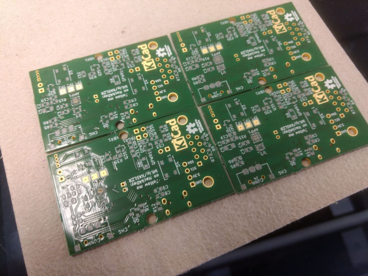
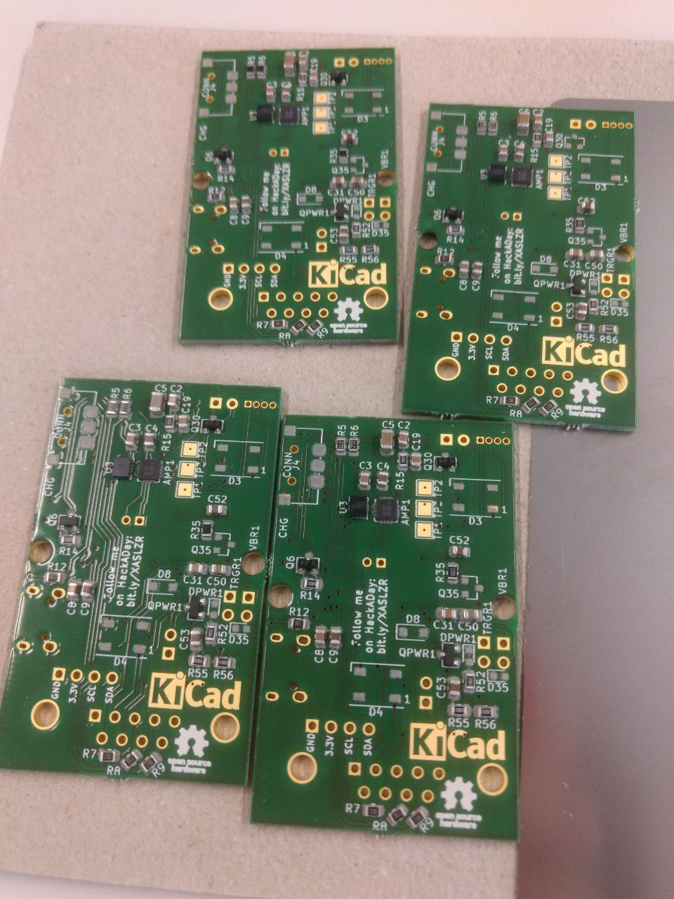
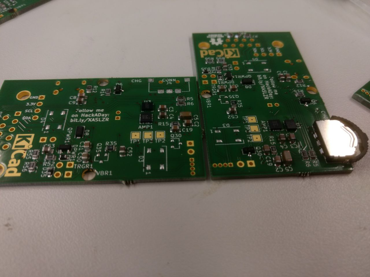
This is no longer the case as of Revision 3.2, and I can proudly say that this project has evolved to have expert hardware.
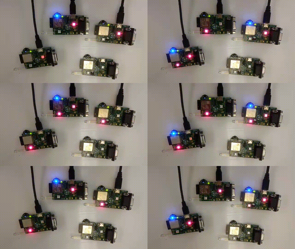
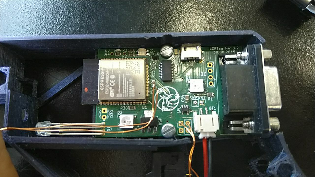
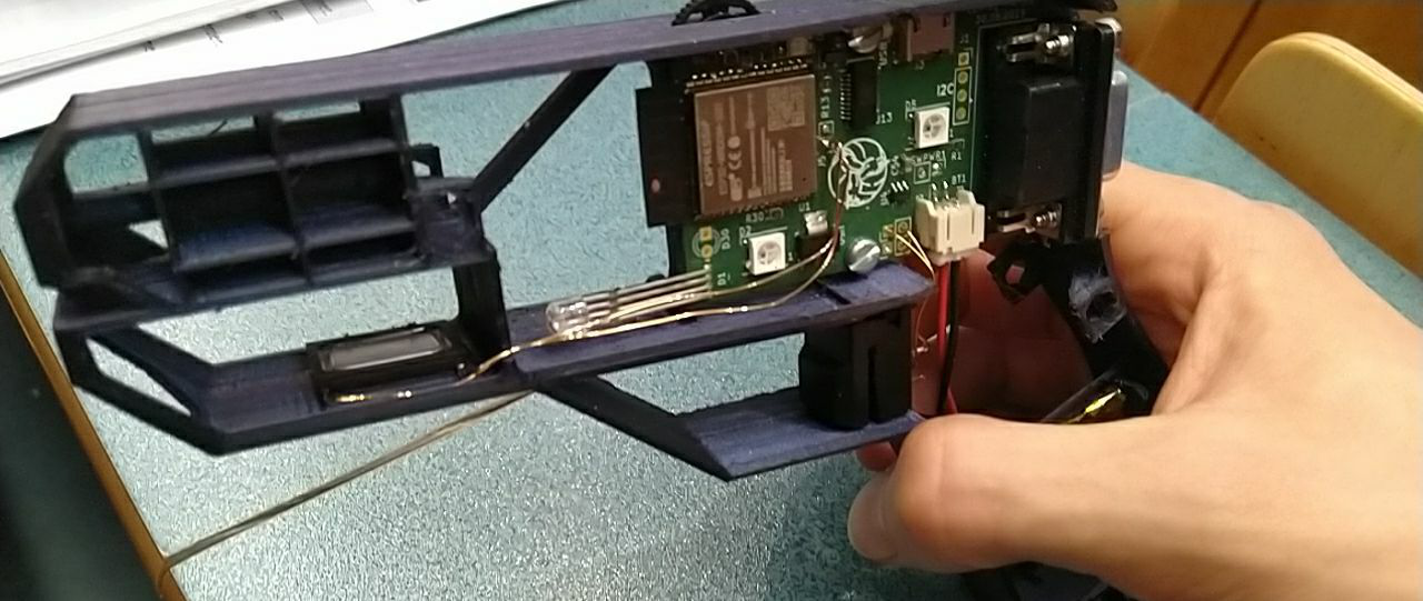
Based on the powerful ESP32 this project's PCB features a set of numerous peripherals to deliver a rich game experience.
These include a 44.1kHz I2S audio amplifier for crisp game sounds, an I2C gyro/accelerometer to detect gestures and player activities, and multiple WS2812 LEDs, both on the PCB and broken out on the vest, to provide colourful visual feedback.
Aside from this the board also contains a robust 3.3V LDO, good capacitance to keep the ESP running, a USB to UART converter with an auto-programming circuit, a LiPo charge circuit with voltage measurement, and a vibration motor to provide haptic feedback.
Despite all this, the boards are designed with ease of use in mind. It features only two components that require hot air reflowing - one of which (the IMU) is optional, the other one can be replaced with a cheaply available breakout board.
All other components are hand-solderable 0805 capacitors and resistors as well as a few TSOP packages - nothing that a fine soldering iron couldn't handle.
Communication between the sets is done via a simplistic but surprisingly effective IR channel. Using 850nm VSCEL IR lasers as emitters, their range exceeds 40 meters in good conditions.
Sunlight sadly reduces this to just a few meters, but during dawn, dusk, or indoors, this will work plenty.
The receivers are made from a simple single-sided board, but even they feature a nice WS2812 LED and high-quality 40kHz VISHAY receivers that provide precise decoding of the IR signals.
Due to the nature of the IR encoding, cheaper AVR based modules like my IR-Bacon can also be used as positioning beacons, providing a cheap way to set up capture points and spawn rooms. The signals can even be expanded to include custom signals, such as grenade shots, weapon type, and other interactions.
The software
Now, this is where it gets a bit more interesting. For Revision 3.2, a lot of the code on both server and client-side have been majorly reworked and documented, making sure they provide a simple but flexible interface for the user to work with.
The ESP32-Side
Based on the ESP-IDF v3.3 the firmware for the ESP has been written in pure C++. This makes sure that it remains fast and snappy in all situations.
The ESP handles a multitude of tasks, the most important of which are:
- Providing a smooth 60FPS LED animation
- Running the I2S sound interface
- Detecting and sending shots,...
 Xasin
Xasin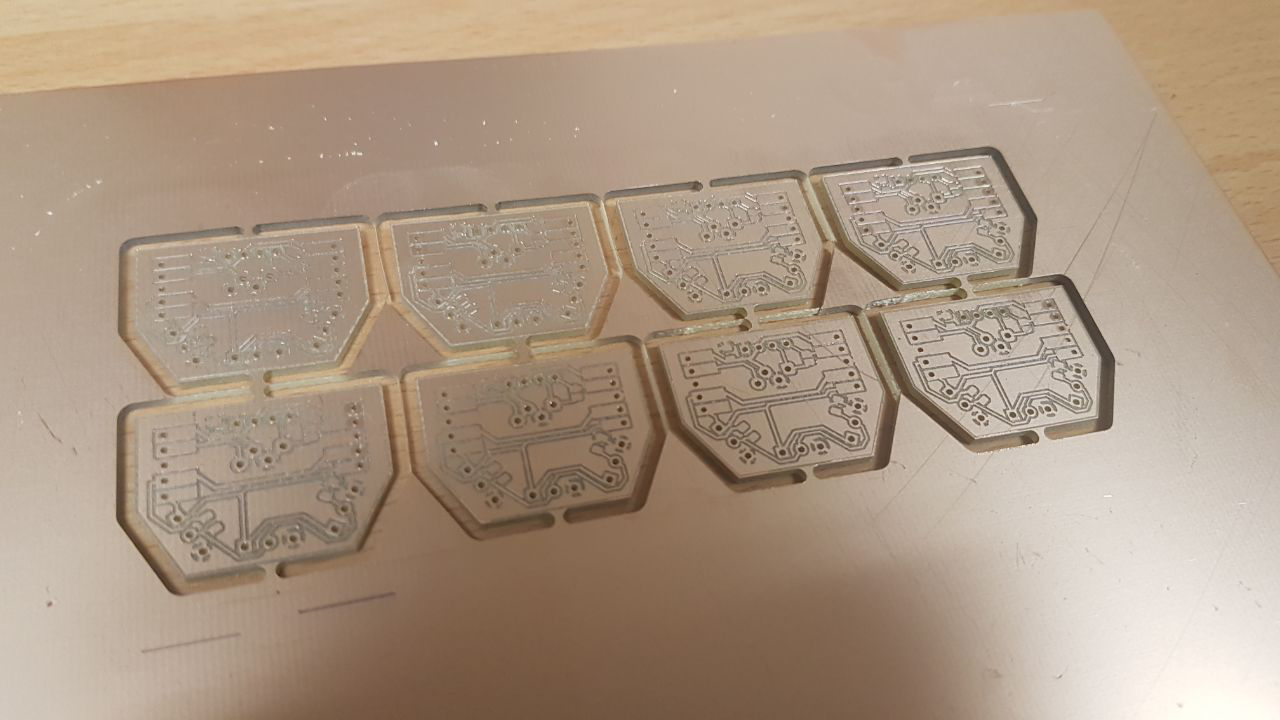





 brtnst
 Eric Wiiliam
 Rodolfo
Do you have a PDF of the schematics? Do you transmit an ID with the shot? How do you do that?