Close
0%
0%

PoE-FeatherWing

Like the Adafruit Ethernet FeatherWing, but with Power over Ethernet built-in!

Similar projects worth following
This projects aims to create a WIZ5500 / Power over Ethernet FeatherWing, fully isolated, in the same size and compatible with the official Adafruit Ethernet FeatherWing (which does not have PoE).

This idea was originally suggested to my by @professor after I released my #wESP32 and has been waiting in the wings for quite a while now. The Adafruit Feather contest made the time seem right for it to come to fruition.

I think it was originally in September of 2018 that @Prof. Fartsparkle suggested to me right here on Hackaday.io to make a project like this as a "successor" to the #wESP32.  Since at the time the wESP32 wasn't even released yet, that seemed a bit premature to me. :)  But I liked the idea enough to do a good brainstorming session.  I don't see it as a successor so much as a nice addition to the PoE products that are available to makers.

There were a couple of potential snags in making a PoE FeatherWing.  The first is that the Feather system didn't intend for FeatherWings to back power the main board.  That doesn't mean that nobody has done this tough. :)  I think many Feather boards now include a diode to prevent back powering the USB port, and for those there is no issue.  There are some that don't include this circuitry though, so the problem had to be managed carefully.

I do this by putting ~4.5V on the USB pin, instead of 5V.  Since the flyback converter of the PoE supply has a diode rectifier on the output, it will just not provide power if there's a voltage higher than its own output on the USB pin already.  I've tested this with a Feather M0 Adalogger which does not include a diode, and my USB port was not blown up. :)

The second potential snag was of course size.  Feather boards are tiny, and Ethernet jacks and flyback transformers are not.  It took a 4-layer board, going to 0402 parts from my usual 0603 (really not an issue nowadays) and using plenty of resistor and capacitor arrays versus individual components to get the needed density.  Initially I wanted to keep all components on one side, and I succeeded in this for the main functionality if you don't count the (optional) 24AA02E48 on the bottom.  But since my CM has no issue or extra charge for double sided components, it's not really an issue.

I used the WIZnet W5500 just as it is used on the Adafruit Ethernet FeatherWing, so it is fully compatible with all the existing software out there.  I also added a 24AA02E48 chip to fix the annoying issue that WIZ5500 chips don't come with a MAC address built-in.

For the PoE side of things, this had to shrink significantly from what I was using on the wESP32.  To that end, the design was built around the TI TPS23758 instead of the Silicon Labs Si3404A.  The chip is slightly bigger, but it implements primary side regulation using the flyback transformer's auxiliary winding, making it possible to drop the huge opto-coupler and all the circuitry around the secondary side shunt regulator.  I also used a 5W instead of the wESP32's 13W flyback transformer as I had done on the #LiFePO4wered/ESP32, since Feather systems don't tend to be power hungry, and the tiny size would just not allow such power while keeping it isolated.  In the end, you can confidently get 3W out of it, 4W is possible but pushing it.  Not bad since the normal USB power into a Feather system is limited to 2.5W.

PoE-FeatherWing-2.pdf

PoE FeatherWing rev 2 schematic

Adobe Portable Document Format - 37.76 kB - 01/09/2020 at 16:51

Preview
Download

PoE-FeatherWing-1.pdf

PoE FeatherWing rev 1 schematic

Adobe Portable Document Format - 35.41 kB - 11/21/2019 at 20:10

Preview
Download

  • M4-Shim manufactured

    Patrick Van Oosterwijck03/24/2021 at 16:35 4 comments

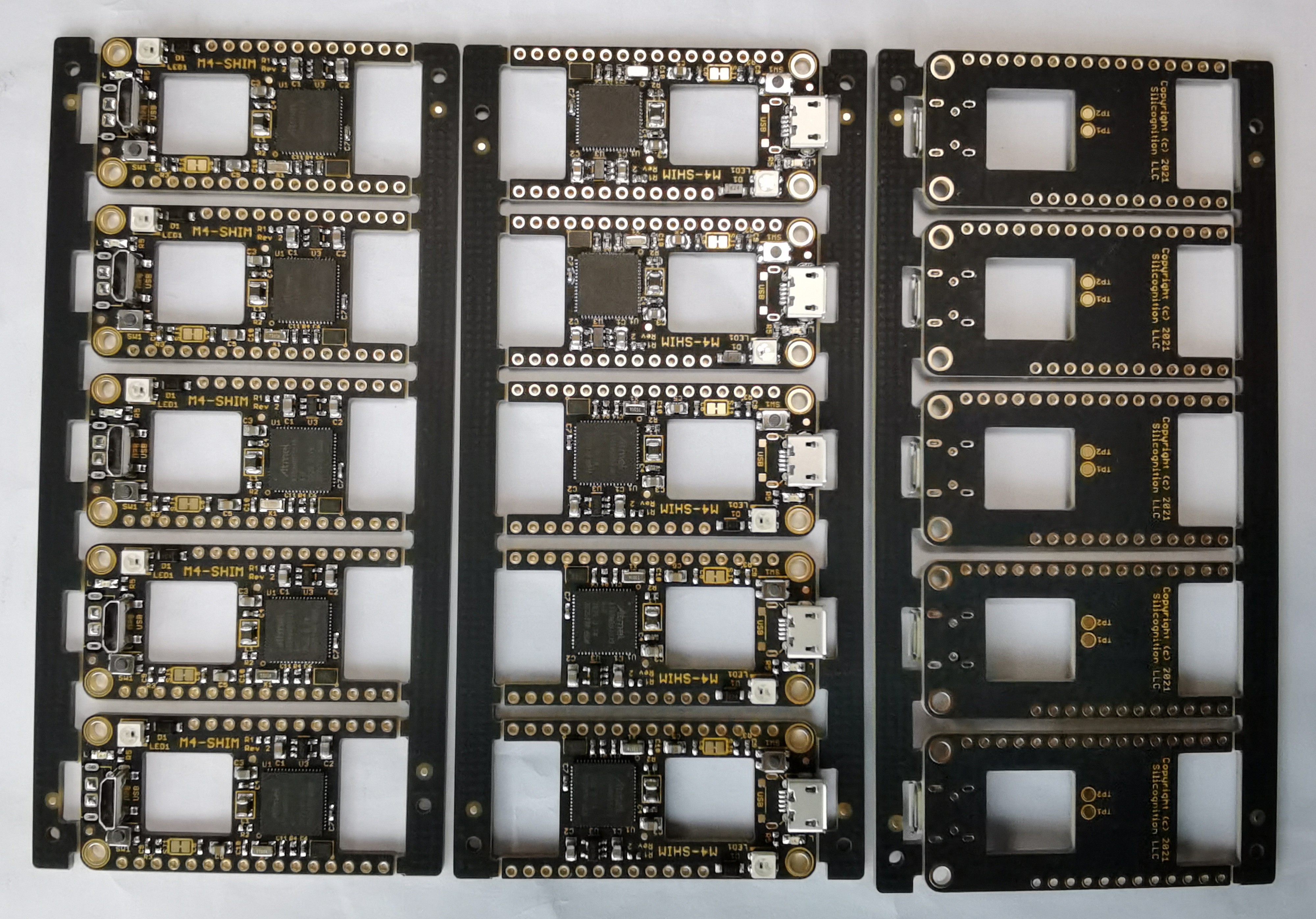
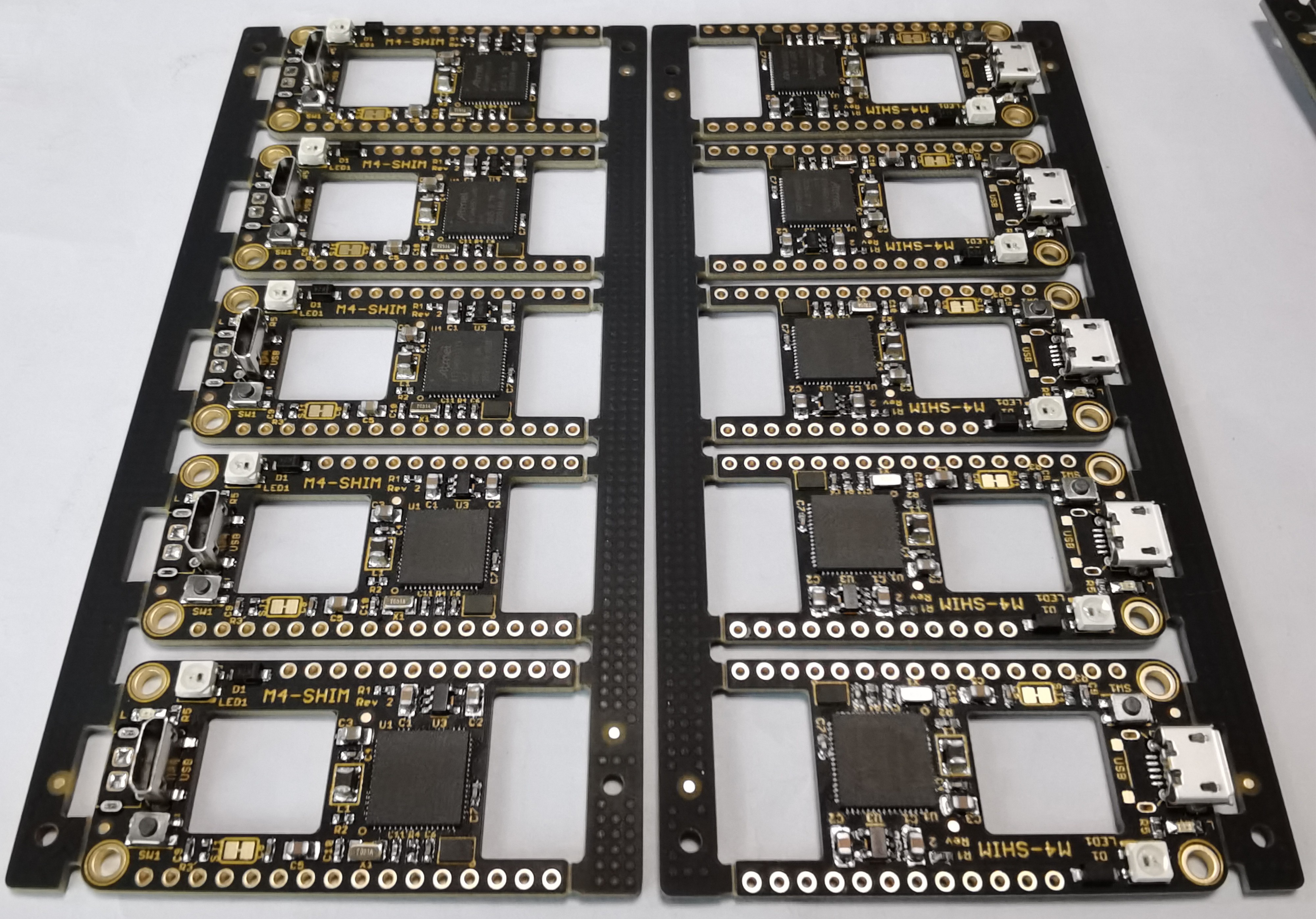
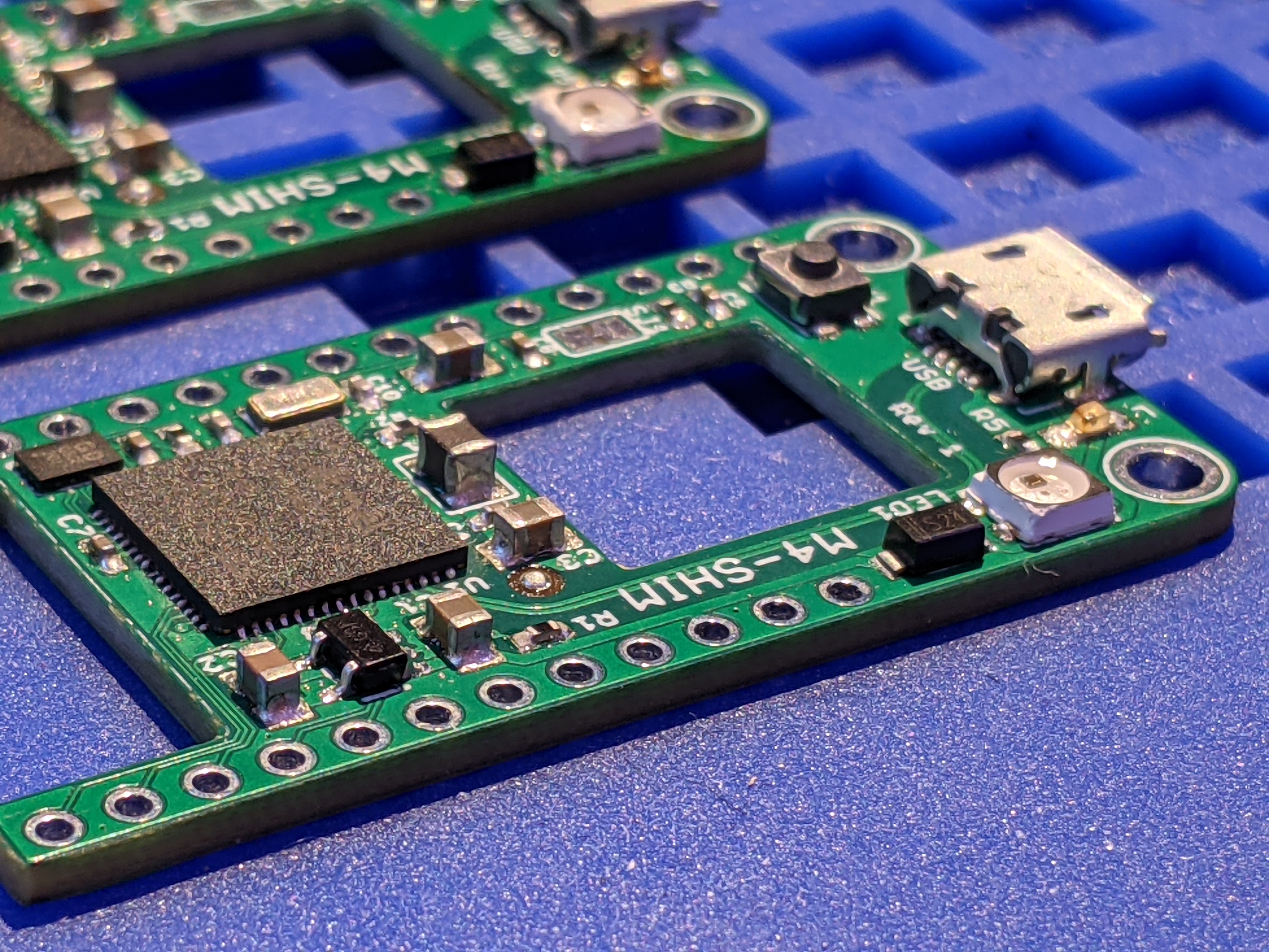
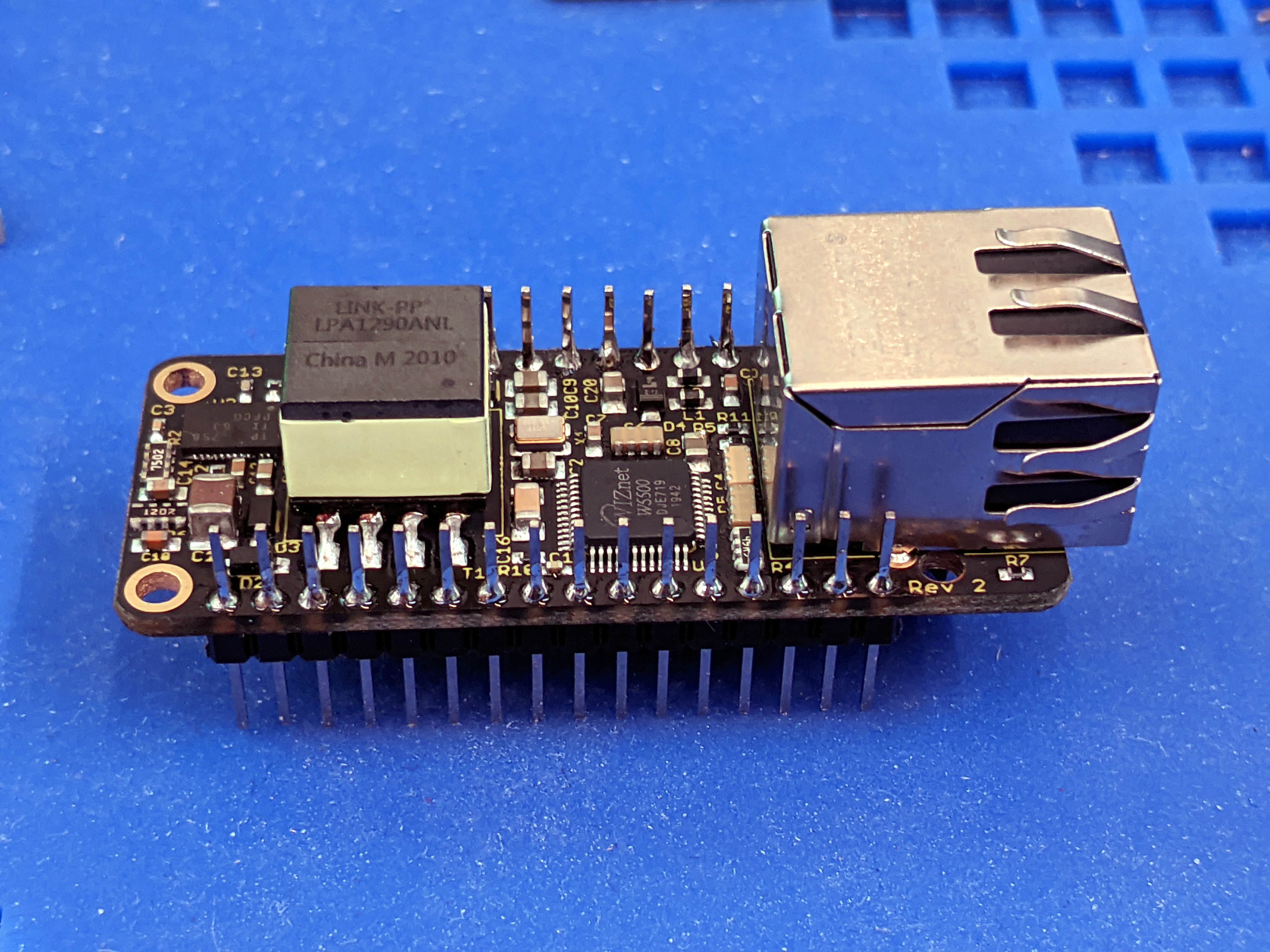
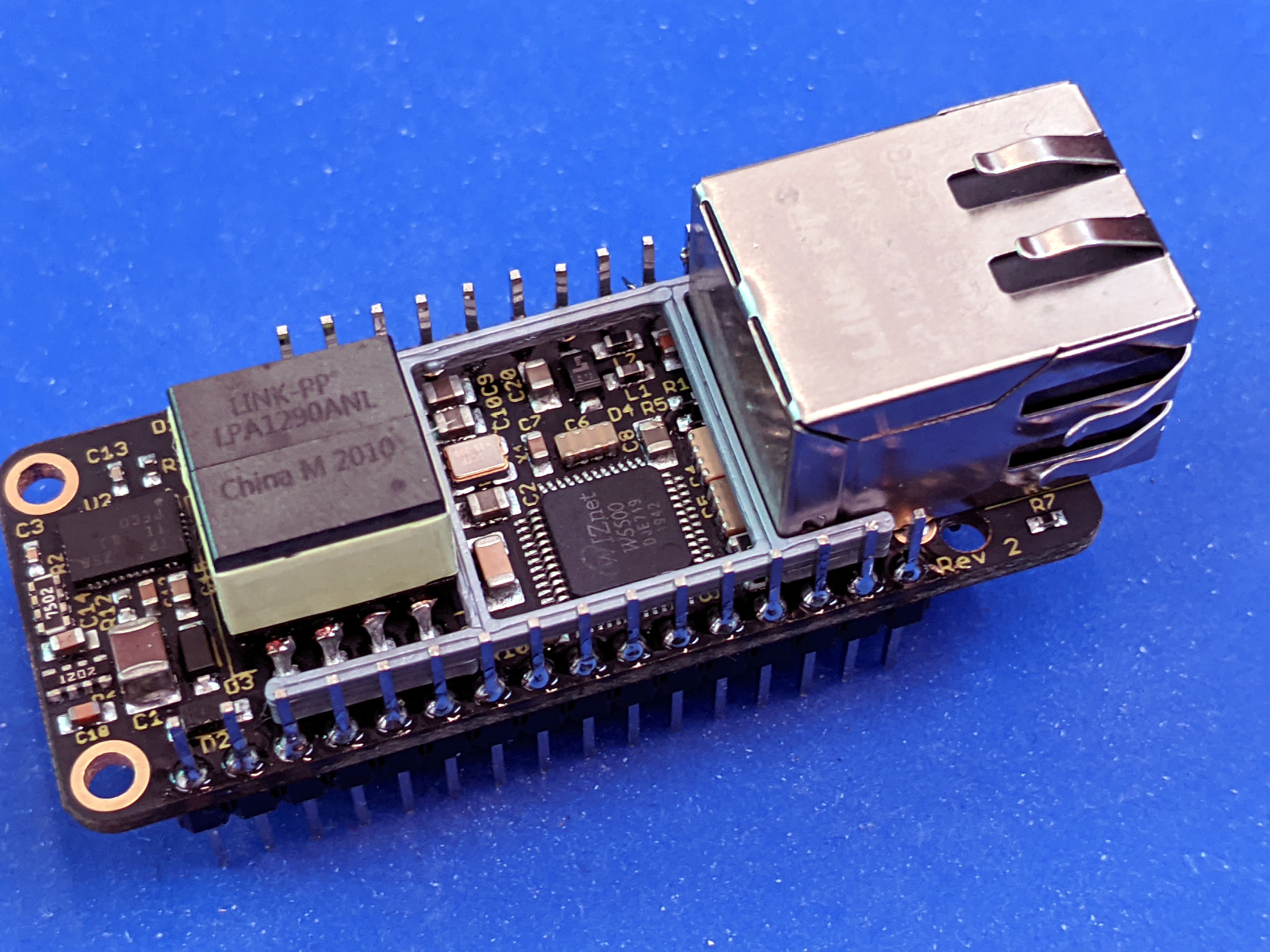
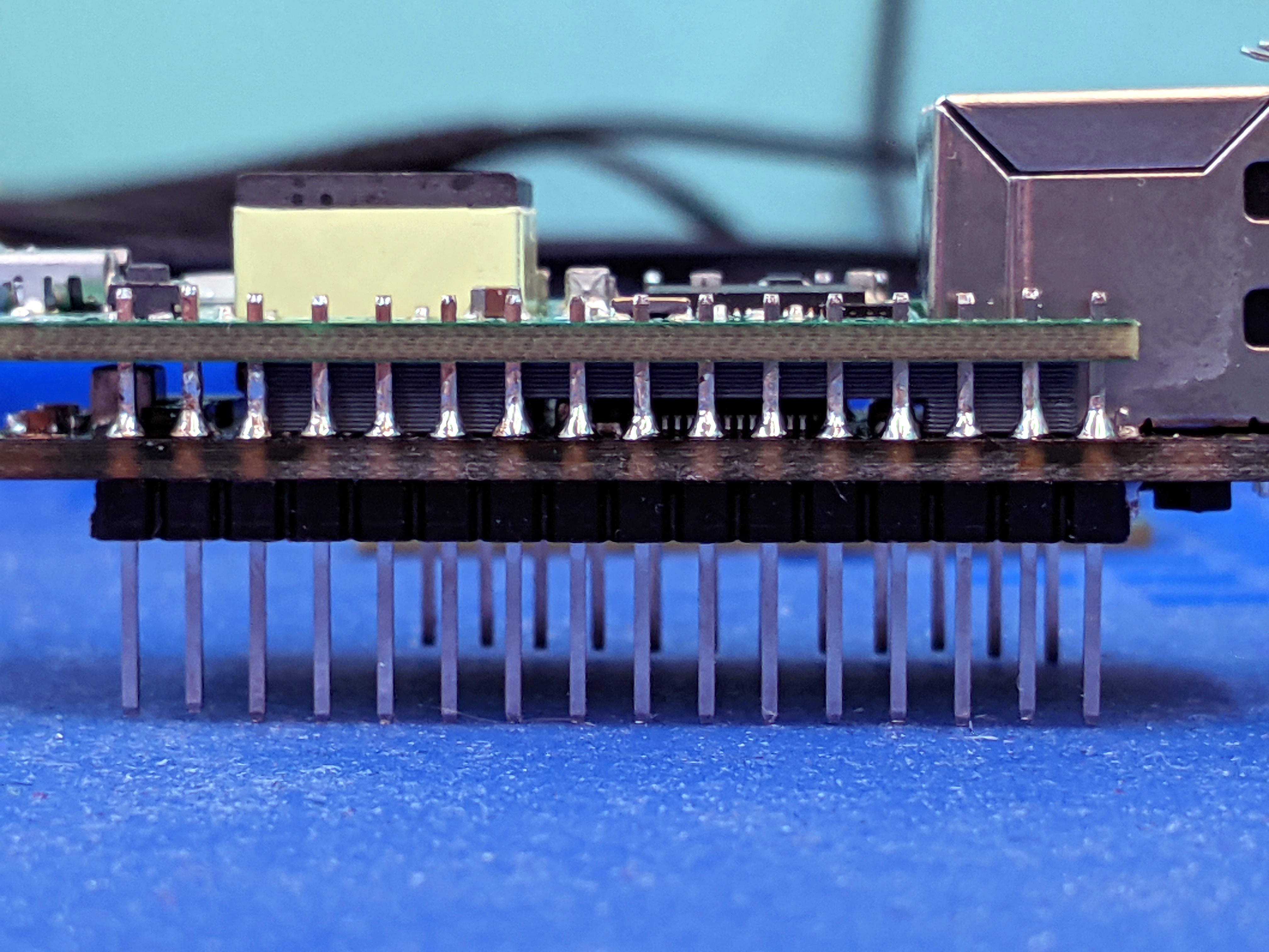
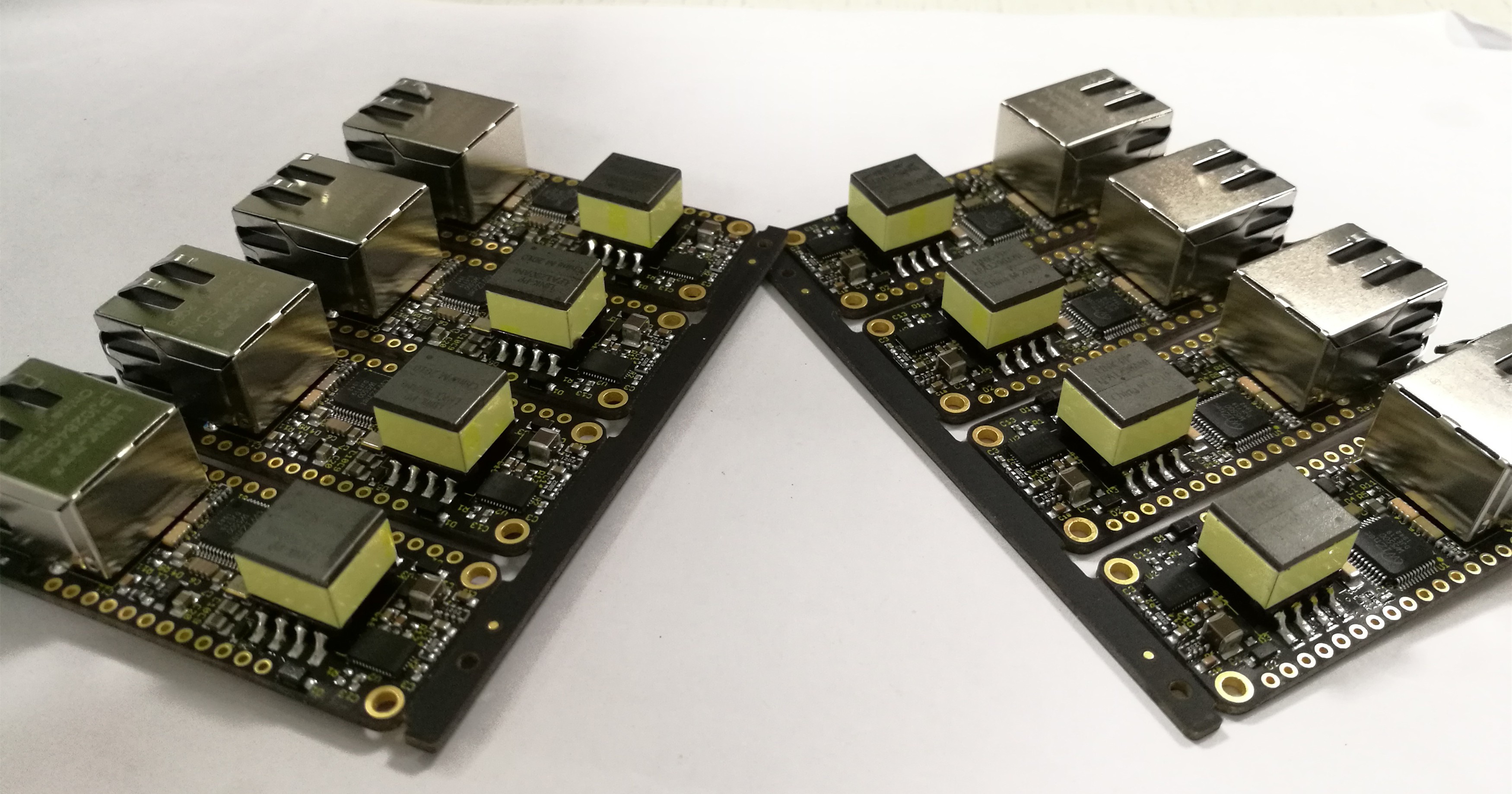
    My contract manufacturer built 200 piece of the M4-Shim, here are some pictures:

    As you can see, I had half of them built with horizontal USB connector, like a normal Feather, and half of them with a vertical USB connector.

    The reason for this is that I have some internal uses I'll probably want to use some of these for, that involve having a stack of 3 PCBs: the PoE-FeatherWing on the bottom; a custom, application specific shim with application specific connectors sticking out the back; and the M4-Shim above that.  The "middle shim"'s connectors would likely interfere with the M4-Shim's USB connector if that was also facing back.  So I made the ones with vertical USB to solve that issue.  By my calculation, with the M4-Shim at the top of the stack, the USB should just clear the top of the PoE-FeatherWing's flyback transformer with enough space for the wall of a plastic case.

    Next the CM needs to program and test them, but I'm waiting for the official 6.2.0 release of CircuitPython, the first to support the M4-Shim, before I can send them all the binaries.

  • M4-Shim

    Patrick Van Oosterwijck12/30/2020 at 21:26 2 comments

    Makers are never satisfied.  (That tends to be why they make! :))

    No sooner had I integrated PoE and Ethernet on a tiny FeatherWing and someone expressed dissatisfaction that they had to use it in combination with a Feather to provide the microcontroller!  They wanted PoE + Ethernet  + microcontroller all in one unit.

    To be honest, I can understand the desire myself.  I love cramming tons of functionality into a tiny footprint.  The Feather is a tiny form factor, but once you start stacking various boards together to make something functional, the total size quickly stops being tiny.  One of the things that bug me about the PoE-FeatherWing is that there is the giant Ethernet jack, and the giant flyback transformer, with so much unused empty space in between.  So I wondered whether I could do something useful with that empty space.  Thus the concept of the M4-Shim was born.

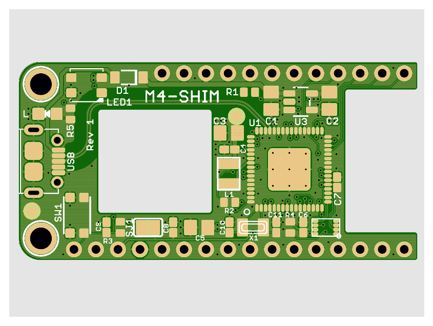
    The idea is to take all the relevant pieces of the Feather M4 Express and fit them into the empty gaps of the PoE-FeatherWing.  This results in a pretty funny shaped board:

    The only thing that's missing compared to the Feather M4 Express is the LiPo battery charge circuitry.  Considering that this is intended to be used with Power over Ethernet, it seems like something that could be dropped to make it fit. :)

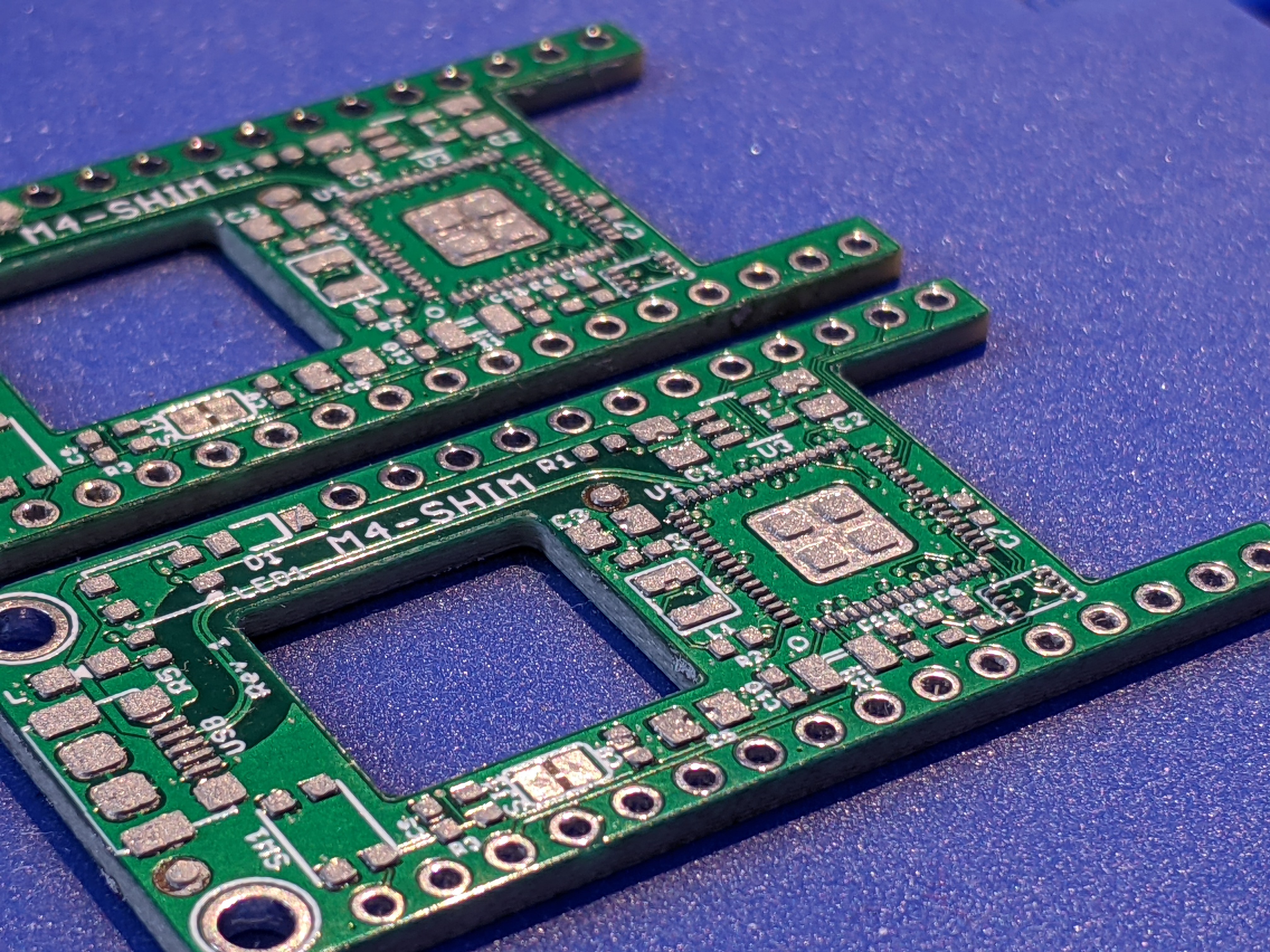
    I ordered prototype PCBs and stencil from JLCPCB and got to work:

    After the shims were built, I first tested them by themselves.  I used my J-Link to program Adafruit's fork of the UF2 bootloader onto the micros.  After that the FEATHERBOOT USB drive came up when connected to my computer, and I could load the latest CircuitPython for the Feather M4 Express successfully!

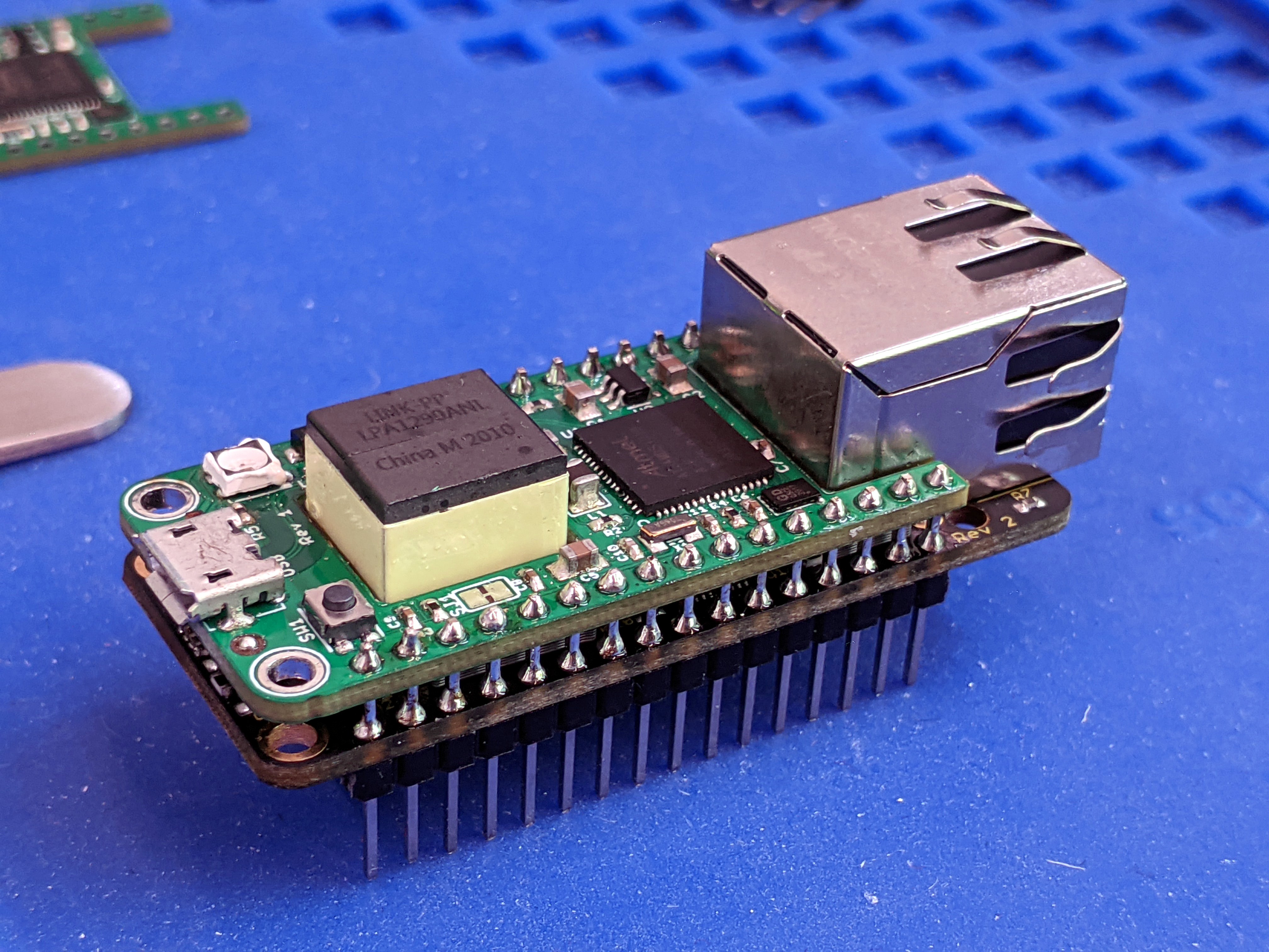
    Then it was time to check integration with the PoE-FeatherWing.  First I installed some long-on-both-sides headers to the PoE-FeatherWing:

    Then I put on a 3D-printed spacer to keep the two boards at the correct separation:

    Next I put on the M4-Shim and made sure the sandwich looked correct:

    Last I soldered the M4-Shim to the pins to finish things up:

    Please ignore the melted-looking RGB LED, it didn't deal well with the rework I needed to do on it but it still works. :)

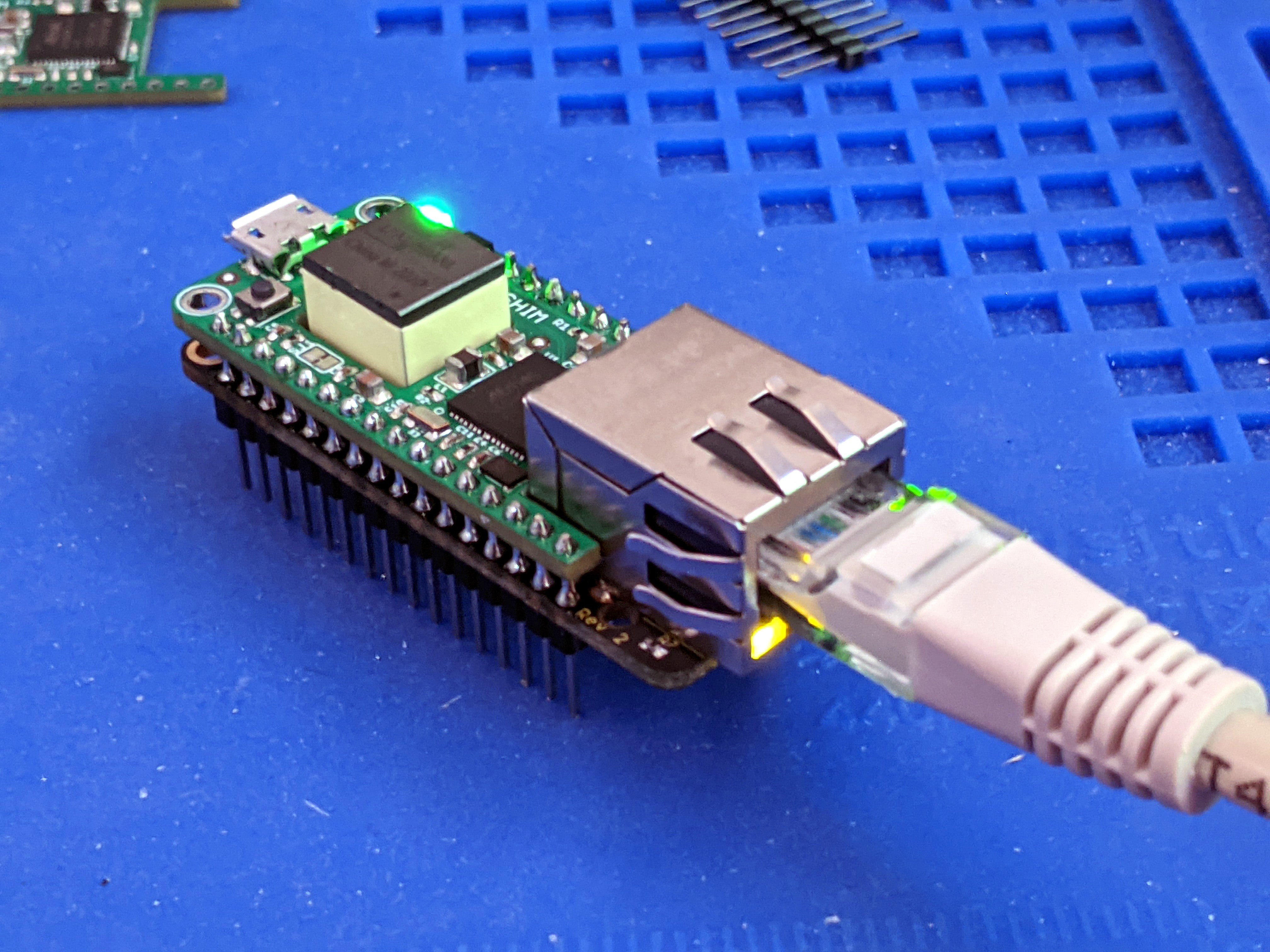
    Alright, time to test if it all works:

    I loaded the CircuitPython example code and after updating it for version 6.x compatibility, it worked fine! :)

    I think I'm going to produce these as an add-on kit for the PoE-FeatherWing.  It definitely helps to keep the whole thing super compact, and now has fully isolated power, network connectivity AND brains.  There's even more space left on top if one wanted to make a third shim, and the whole thing could be kept extremely compact if the connecting pins are installed differently so they don't stick out on the bottom.

  • Crowd Supply campaign live!

    Patrick Van Oosterwijck07/16/2020 at 18:40 0 comments

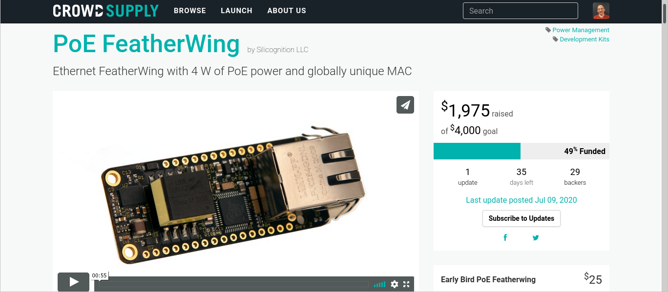
    Whew, too much going on!  I forgot to post here that my PoE-FeatherWing Crowd Supply campaign is live!

    https://www.crowdsupply.com/silicognition/poe-featherwing

    We made a good start and are nearly halfway funded, but we still need your help to make it.  Thank you for your support!

  • CircuitPython troubles and flyback change

    Patrick Van Oosterwijck06/02/2020 at 20:15 0 comments

    Much progress has happened, here's a recap:

    CircuitPython troubles

    I previously reported that I had successfully tested compatibility with CircuitPython.  Seems I wasn't thorough enough: this had proven compatibility from a software standpoint, that the W5500 CircuitPython driver worked correctly with the PoE-FeatherWing.  Problem was: to see what was going on by console prints, I also had the USB connected.

    A problem became obvious when I was building the test fixture, which I'm basing on a Feather M4 running CircuitPython.  It would not run my test code with powered from the PoE-FeatherWing.  I adjusted my demo code to light up some LEDs and confirmed that my demo code also didn't run when powered from the PoE-FeatherWing, without USB connected.

    The system kept ending up in "safe mode", which meant it would not run my Python code.  After some diffing through the CircuitPython source code, I found out that safe mode was in this case being triggered by a brown out detector (BOD) reset.  Did my power supply really brown out?

    Turns out, the problem was because of the pretty slow ramp up of the PoE power.  CircuitPython sets the BOD level to a pretty high 2.77V in its initialization code, to make sure the system voltage stays within the safe range for SPI flash chips.  Power on reset would release at 1.7V, the micro would start initializing and get to the point where the BOD level was set to 2.77V before the power supply had time to reach this level!  This would cause a BOD reset, the chip would start initializing again, and by the time the BOD level change was reached, it would the power supply was high enough and the system would run.  But, because of the BOD reset, it would run in safe mode, not loading any Python code.

    It was obvious this could be fixed with a software change, but because I really did not want to start maintaining a separate CircuitPython branch for PoE-FeatherWing compatibility, I filed an issue with CircuitPython and simultaneously started to see if I could do anything in hardware.

    I found that I could make the code run if I added a 4.7 uF capacitor from the EN pin to GND.  In combination with the pull-up on the Feather, this would delay the turn-on of the 3.3V regulator on the Feather, enough to give the input voltage time to ramp up before the BOD level was changed to 2.77V.

    While it would be possible to add this to my PoE-FeatherWing, it still felt like a hack.  It depended too much on the exact implementation of the EN pin on the Feather, something out of my control.  And a quick check showed that various Feathers used different values of pull-up resistors, and different 3.3V regulators that may have different enable thresholds.  There was always the risk that even if I tested that it would work with every Feather currently on the market, it could still fail on a Feather released in the future that used some different arrangement on EN.

    Luckily it turned out to not be necessary.  In a prompt response to the issue I had submitted, I was told that this had been solved in the UF2 bootloader.  They had already added code to wait for the voltage to reach 2.77V before loading CircuitPython in bootloader version 3.9.0.  Although I had updated the CircuitPython on both my test boards, I had failed to also update the bootloader.  Moral of the story: update both the CircuitPython image and the bootloader on every Feather you buy before use!  Oh, the joys of modern software development.

    So, this turned out to be a tempest in a teapot.  I'm glad there is a software solution already in place, as it is the best way to solve this.  With this unblocked I could also continue on my test fixture.

    Flyback change

    On the #wESP32 I had used a Hanrun HR861153C PoE Ethernet jack, but I had tested and confirmed that equivalents from other manufacturers such as Link-PP worked just as well.  Link-PP...

    Read more »

  • More testing completed

    Patrick Van Oosterwijck05/20/2020 at 00:10 0 comments

    I found the time to do more testing, and most of it is good!

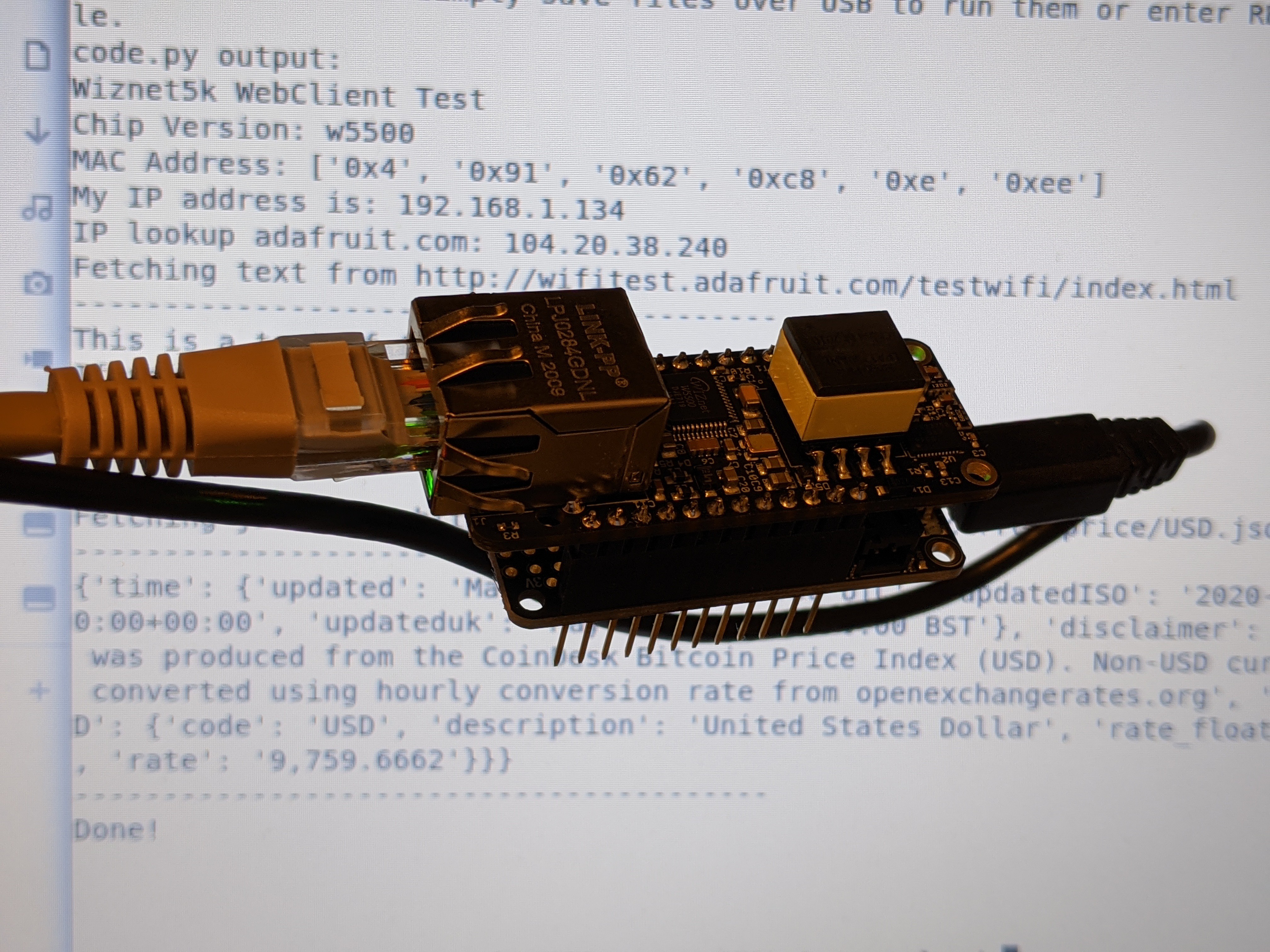
    The first thing on my list was to test with CircuitPython.  This turned out to be more involved than expected.  Turned out the Feather M0 Adalogger was not compatible with the W5K CircuitPython driver due to the use of longs.  So I had to get a Feather M4 Express to make it work.  Then it didn't seem to be working, until I remembered it was probably a good idea to update my board to the latest version of CircuitPython, versus using the one the board came with.  That solved all my problems:

    Yes, I also have USB connected to be able to see the console, but it works without as well.

    I added this code to the standard Adafruit example to read the MAC from the 24AA02E48 and use it:

    # Read the MAC from the 24AA02E48 chip
    mac = bytearray((0xDE, 0xAD, 0xBE, 0xEF, 0xFE, 0xED))
    i2c = busio.I2C(board.SCL, board.SDA)
    while not i2c.try_lock():
        pass
    i2c.writeto(0x50, bytearray((0xFA,)), stop=False)
    i2c.readfrom_into(0x50, mac, start=0, end=6)
    i2c.unlock()
    
    # Initialize ethernet interface with DHCP and the MAC we have from the 24AA02E48
    eth = WIZNET5K(spi_bus, cs, mac=mac) 

    Next up: the Giant Board!

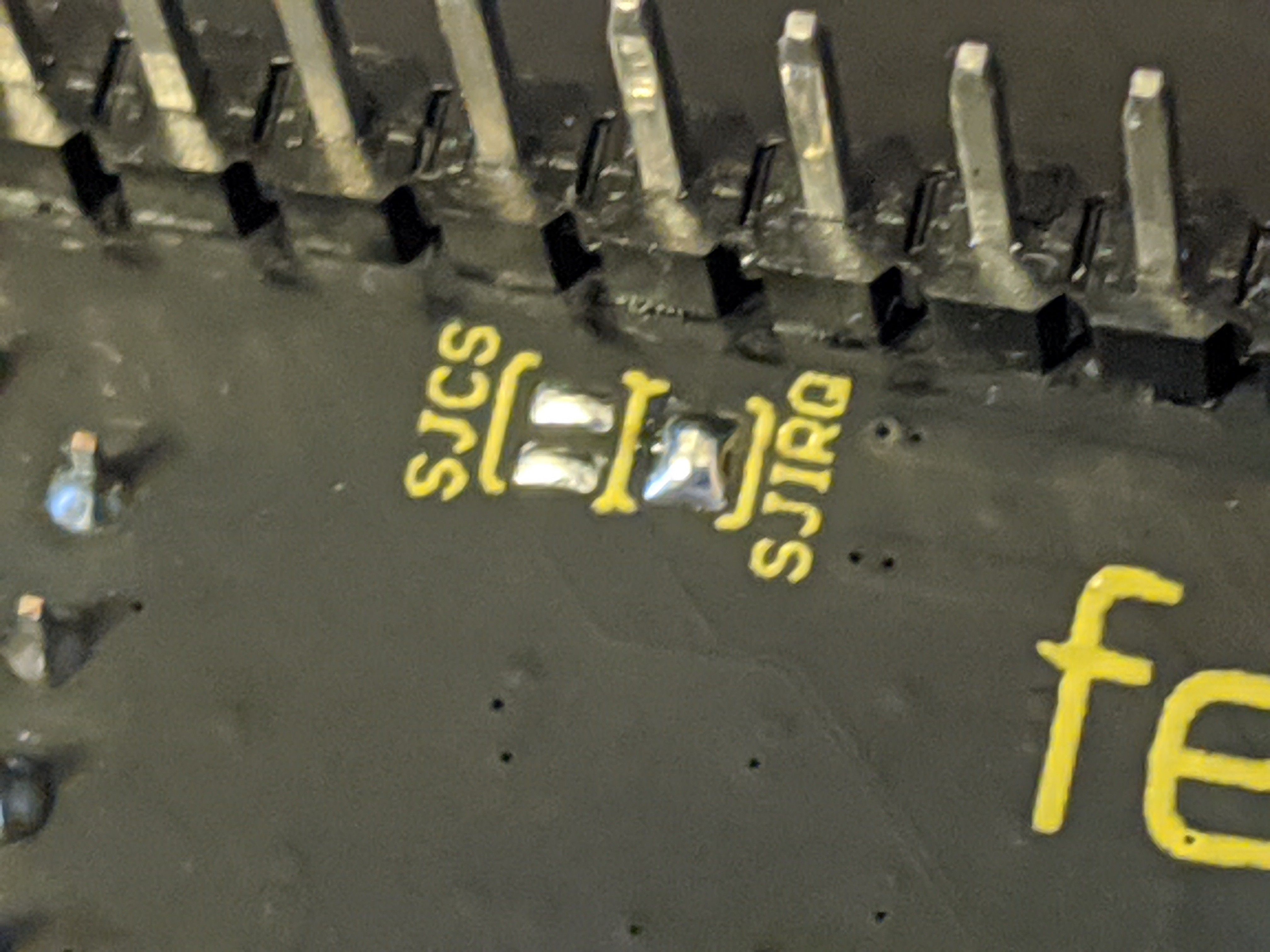
    I just followed the documentation to get the Ethernet FeatherWing to work on the Giant Board, with one small exception: instead of having to run a separate wire to "connect the IRQ pin on the end of the Ethernet FeatherWing to the pin PD31 on the Giant Board", you can just bridge the solder jumper!

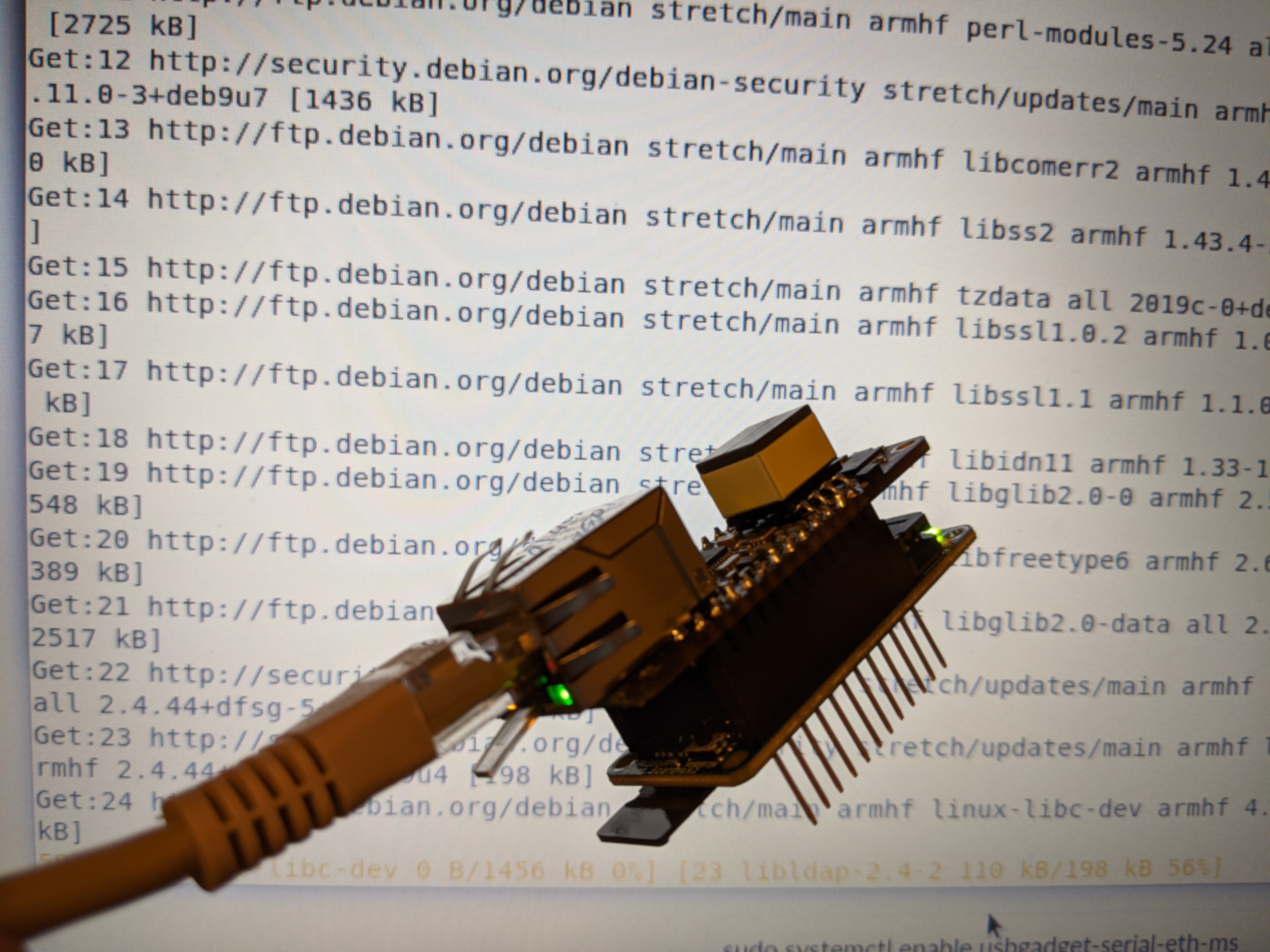
    That's so much better.  After doing this and putting the boards together, it worked right away!  Here you can see me doing an `apt upgrade` through the Ethernet, and powered from Ethernet, connected over ssh:

    Success!

    I had one weird thing happen though, and it's a bit worrying.  At some point, I was using a stupid cable of which the clip had broken off, and the cable disconnected in the middle of an `apt update`.  No worries, I reconnected with a better cable, but after that, the PoE-FeatherWing didn't work right any more.  The symptoms are very bizarre.  At first I wondered if it was just a problem with the Giant Board, but my two other Feathers showed the same issue.  The W5500 works, but only if connected to my router without PoE.  The PoE power works as well, but no data communication happens when connected to (and power conversion happening from) the PoE router.

    I don't have a clue yet what exactly happened.  Just disconnecting the cable can't really have done it (whatever 'it' is), because I've done that a lot with other boards, and there's never an issue.  Currently my theory is that the "sliding out" causes a long term intermittent connection that may have over-stressed something.  Not something I enjoy finding out, but at least I can hopefully track down what failed and fix it before producing the remaining 900.

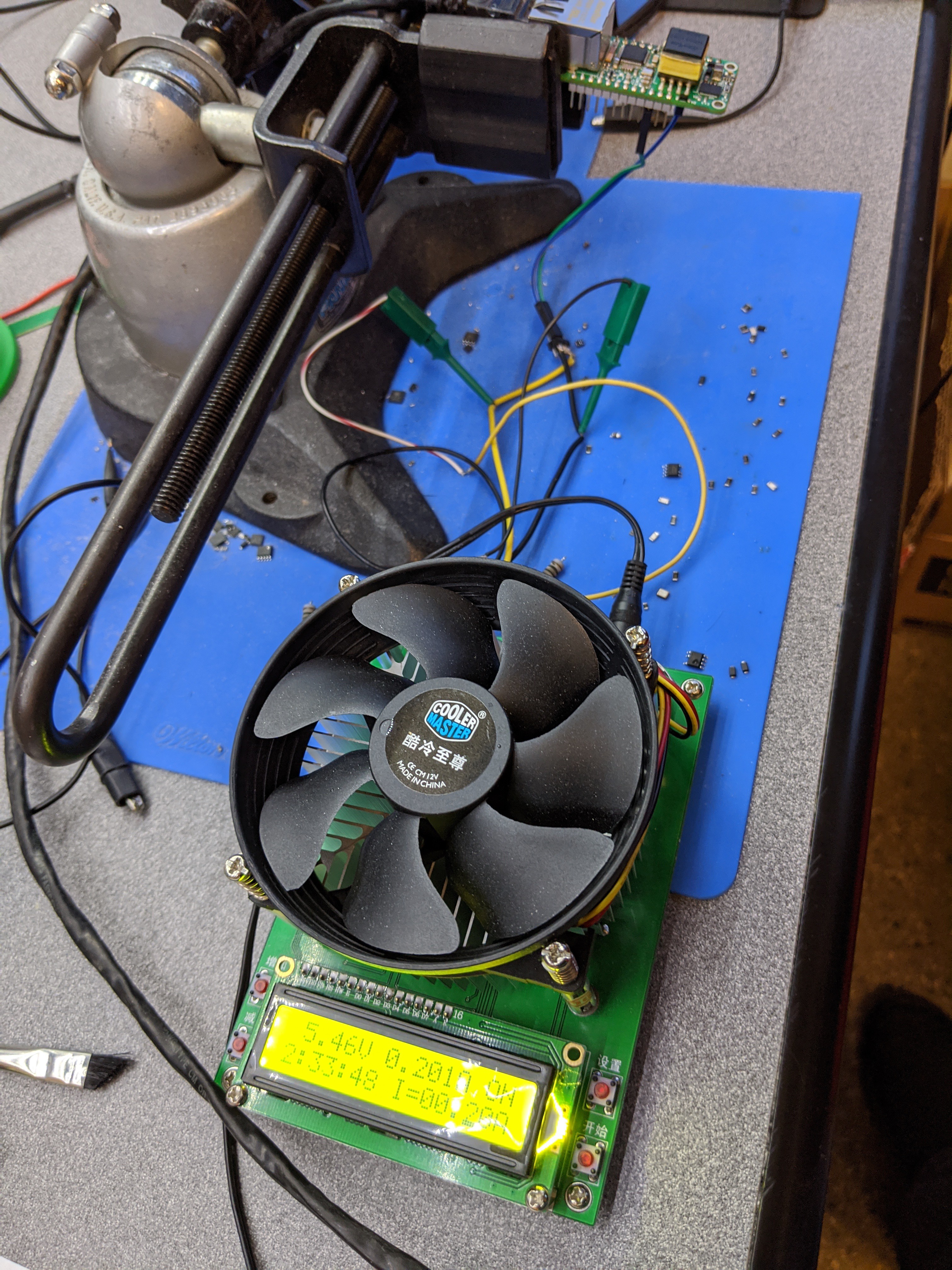
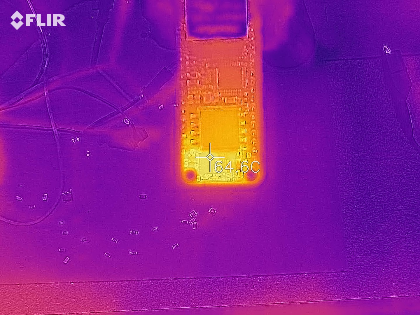
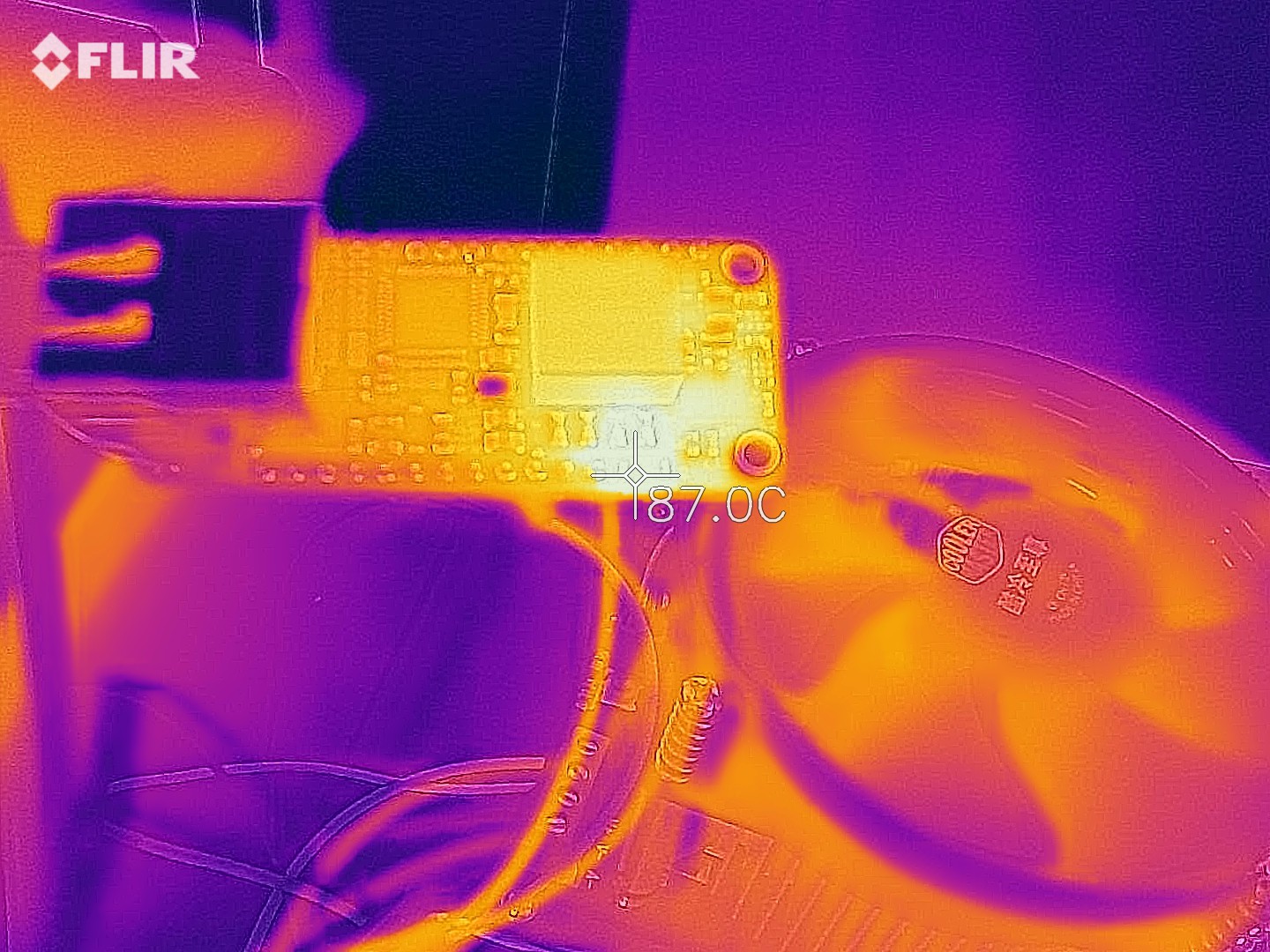
    Last thing on my list was load testing.  I need to do it on more boards, but at least on the couple I have tested, I've been able to pull 1A and keep the voltage above 4V, which is sufficient to keep the 3.3V regulated.  The secondary Schottky diode rectifier gets quite hot at this current:

    While it would be nice to play the numbers game for marketing and say that the design supports 4W, I think with the space constraints we're dealing with, it's probably not the best idea to run at 4W.  On USB, Feather systems have 2.5W available to them, and I think specifying the PoE-FeatherWing as a 3W system is a safe conservative number.

    This is a thermal shot when running at 3W:

    Still toasty, but much better!

    Next up: figure out what went wrong with the unit that won't communicate when running from PoE.

  • First CM prototypes!

    Patrick Van Oosterwijck05/10/2020 at 01:04 0 comments

    It's been quite a while since the last update.  First there was the Chinese new year, and then the Covid-19 situation caused major delays with pretty much everything.

    In my case, the delay was mostly due to delays in the manufacturing of the flyback transformer and Ethernet jack by Link-PP.  I had decided I had enough confidence in the rev 2 layout to go to my contract manufacturer KingTop instead of doing another prototype round myself.  The plan was to immediately order 1000 pieces (to get bulk pricing) or most parts, but only 100 PCBs at first.  Then when everything seemed alright with the 100, have the 900 remaining units built.

    I finally received word from KingTop that Link-PP had delivered the parts necessary to build the first round of 100.  They had received 1000 Ethernet jacks and 100 flyback transformers (since we hadn't tested their flybacks before).

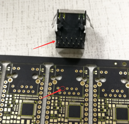
    Then I got some bad news: the Ethernet jacks had an extra pin and did not fit into the PCBs!

    That was an unexpected horrible thing to happen!  Both the datasheet and the samples I had previously received from Link-PP had this pin missing.  Now we ordered 1000 pieces and they were all wrong.

    Luckily, KingTop and Link-PP were both responsive and helpful to deal with the problem.  Link-PP confirmed that the pinout was correct and the extra pin was unused.  They just seem to have a variant of this jack with and without that pin.  Odd that they would have the same part number, that seems to be asking for trouble!

    It was decided that for the build of 100 prototypes, KingTop would cut the pin, while they shipped the remaining 900 back to Link-PP for replacement.  With that settled, KingTop went to work quickly and built the units.

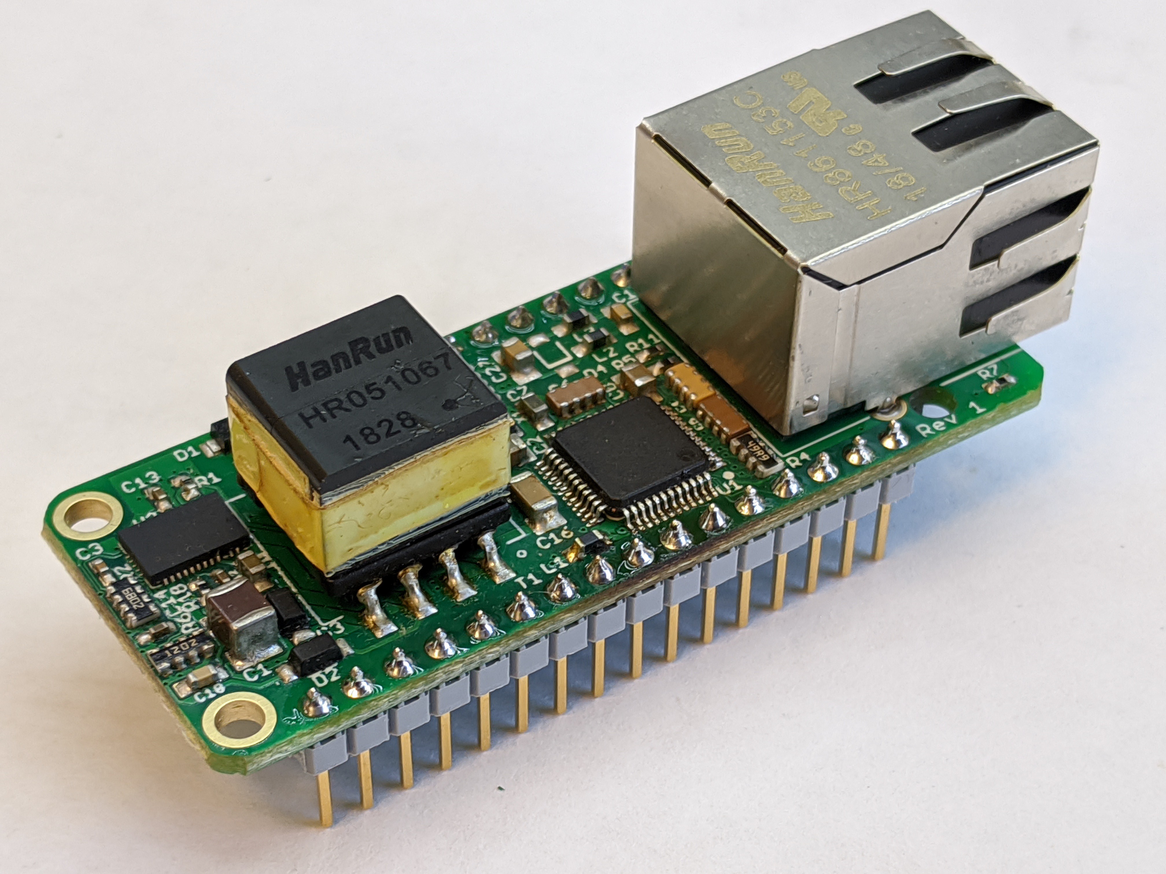
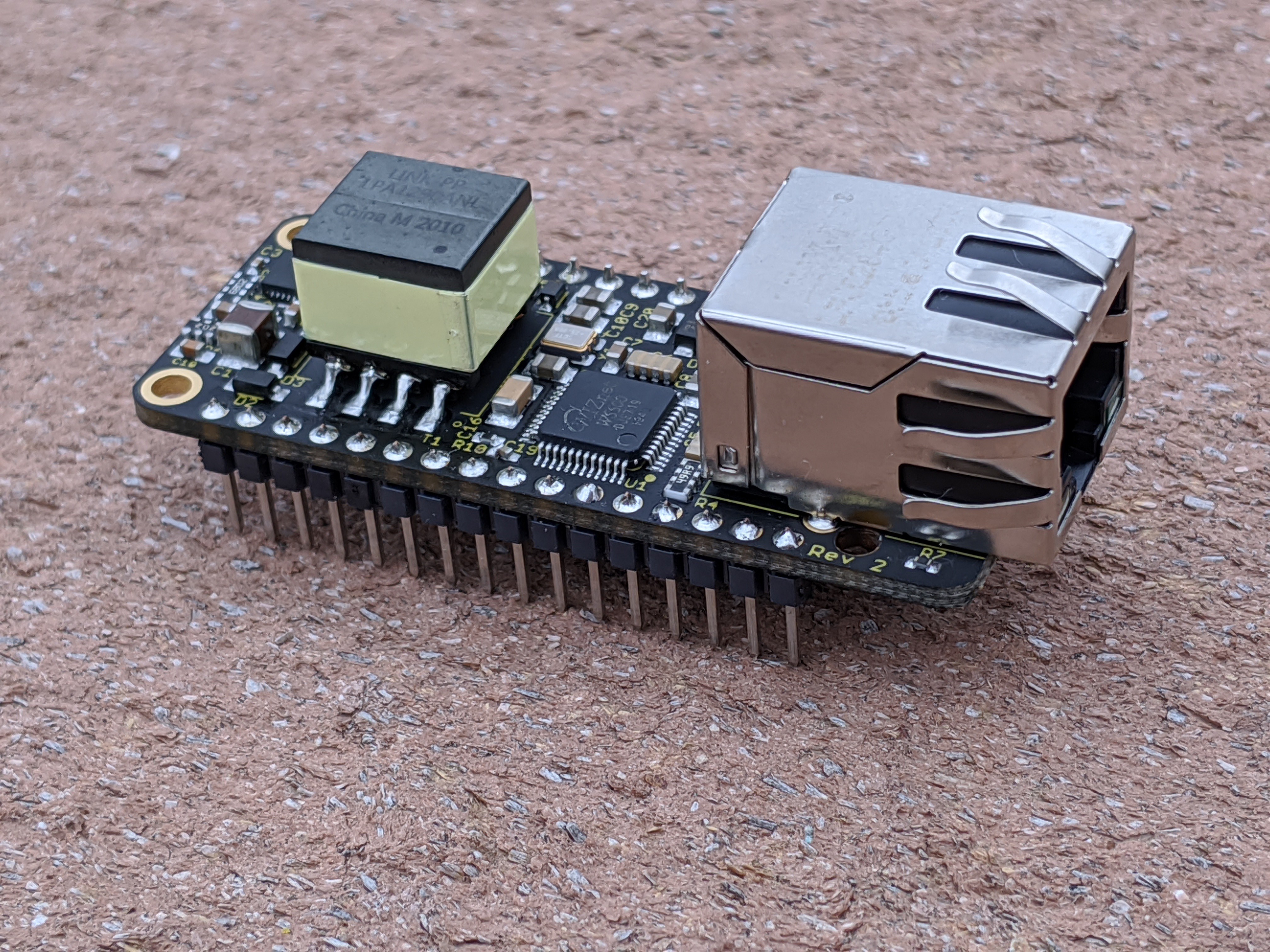
    Looking good!  They shipped them and I received them late this week.  I added pins to a test unit:

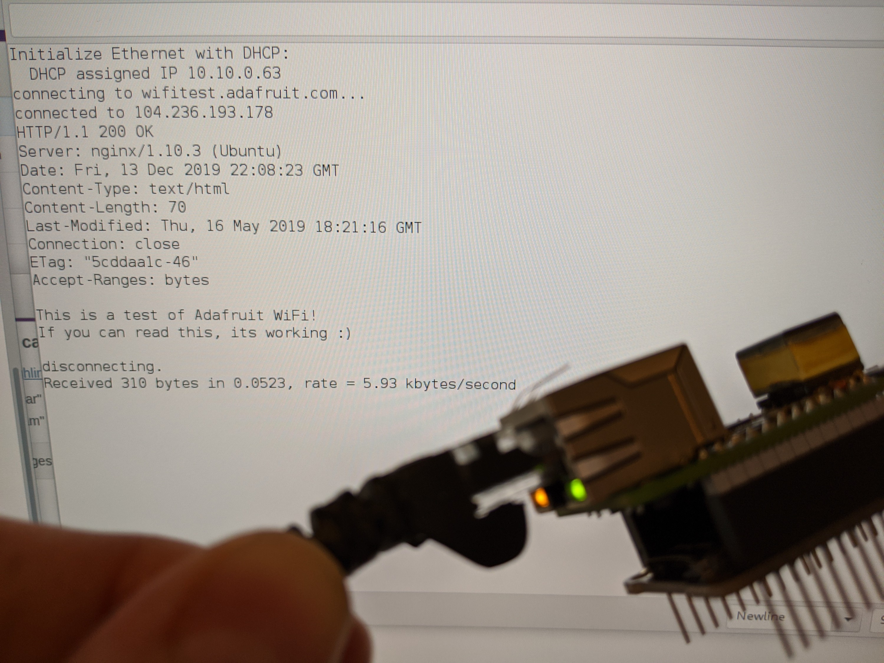
    Then I put it to the test by connecting it to a Feather M0 Adalogger board programmed with an Arduino sketch and hooking it up to a PoE switch:

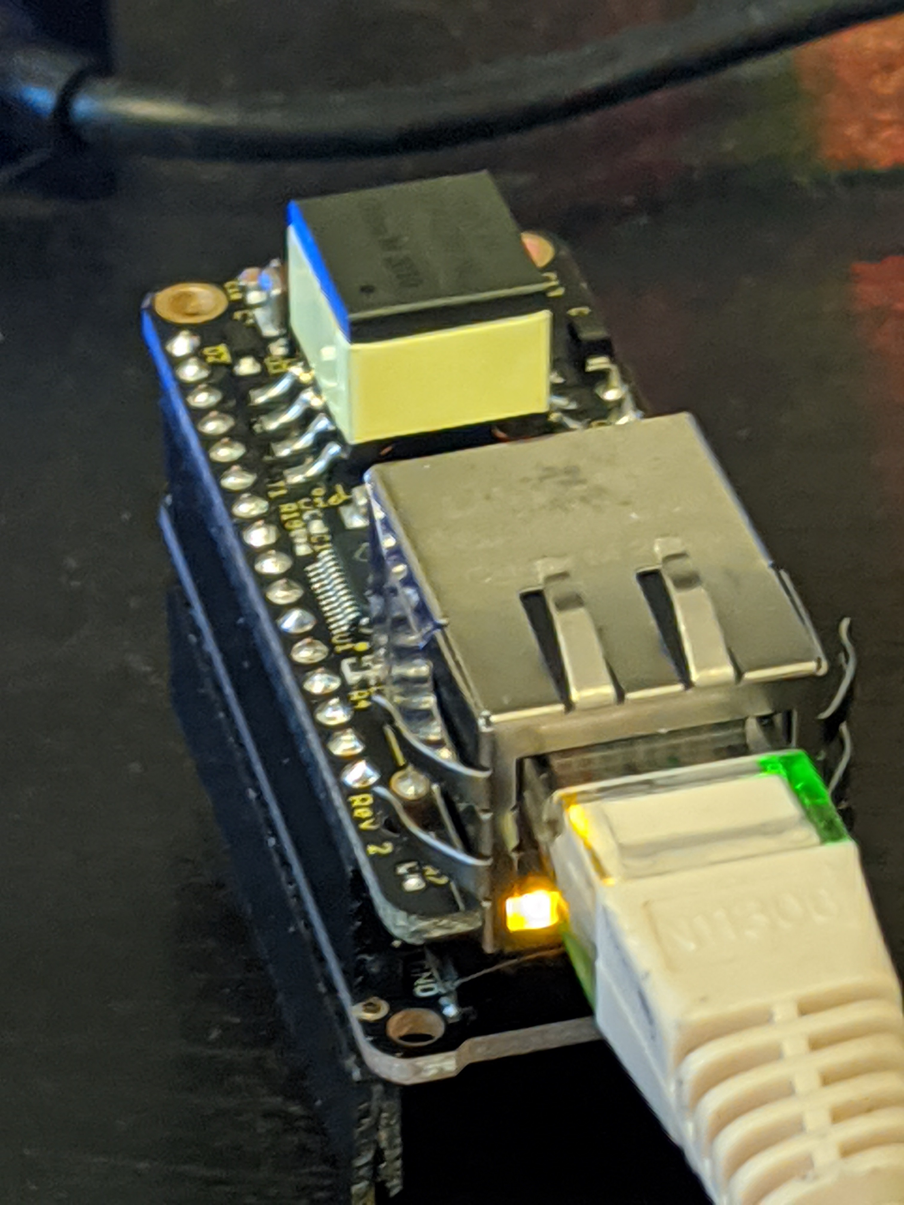
    It immediately worked!

    I have now confirmed the PoE section works, the W5500 works, and I also checked that I could load a valid MAC from the 24AA02E48 chip.  Still to do:

    • Check how much power the PoE section can deliver, on a statistically relevant number of boards.
    • Test that it works with the W5500 CircuitPython module.
    • Test that it works with the Giant Board.
    • Get to work on the Crowd Supply campaign. :)
    • Design and build a test fixture for production.
    • Get KingTop to build and test the remaining 900 units.

  • Rev 2 layout

    Patrick Van Oosterwijck01/08/2020 at 19:06 0 comments

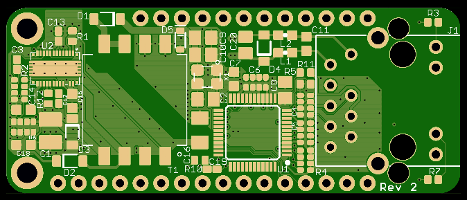
    Revision 2 of the PCB layout implements the changes needed to make rev 1 functional, plus some additional goodies:

    • Added D5 5.6V zener diode on the PoE output voltage to limit the output voltage under no or low load conditions by providing a minimum load if the voltage goes too high.
    • Changed C14 to 4.7uF in 0603 package to make the primary side regulation stable.
    • Removed L1 ferrite bead and added C16 and R10 to reset the W5500 on power-up.
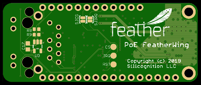
    • In addition to the default-closed solder jumper that connects the W5500 CS line to pin 22 of the Feather footprint, as present on the Adafruit Ethernet FeatherWing, I also added a default-open solder jumper to connect the W5500 IRQ line to pin 24 of the Feather footprint.  This keeps it 100% out-of-the-box compatible with the Adafruit Ethernet FeatherWing, while at the same time making it compatible with the Giant Board without having to run extra wiring, but by just bridging this jumper instead.
    • As mentioned before, I had the desire to have a 24AA02E48 on the board to provide a globally unique MAC address since the W5500 doesn't come with one, but I ran out of space for it.  I decided to add footprints for this chip plus I2C pull-ups and decoupling cap to the bottom of the board (U3, R8, R9 and C17).  Maybe I can produce versions with and without the chip, or maybe I'll just leave them unpopulated so the user can add the parts if desired, or maybe it won't be a problem for the CM to always have it.  Either way, it doesn't hurt to have the footprints present while I figure it out.  I'd like to get feedback on how useful you think this is in the comments!
    • Renamed the solder jumpers SJCS and SJIRQ to make it more clear what's what.

    The resulting layout looks like this:

    Time to get some boards made!

  • W5500 initialization

    Patrick Van Oosterwijck01/08/2020 at 18:25 0 comments

    In the last update I reported that I needed to find a way to reset the W5500 after power-up from PoE for it to initialize correctly.  I found some time to work on that yesterday.

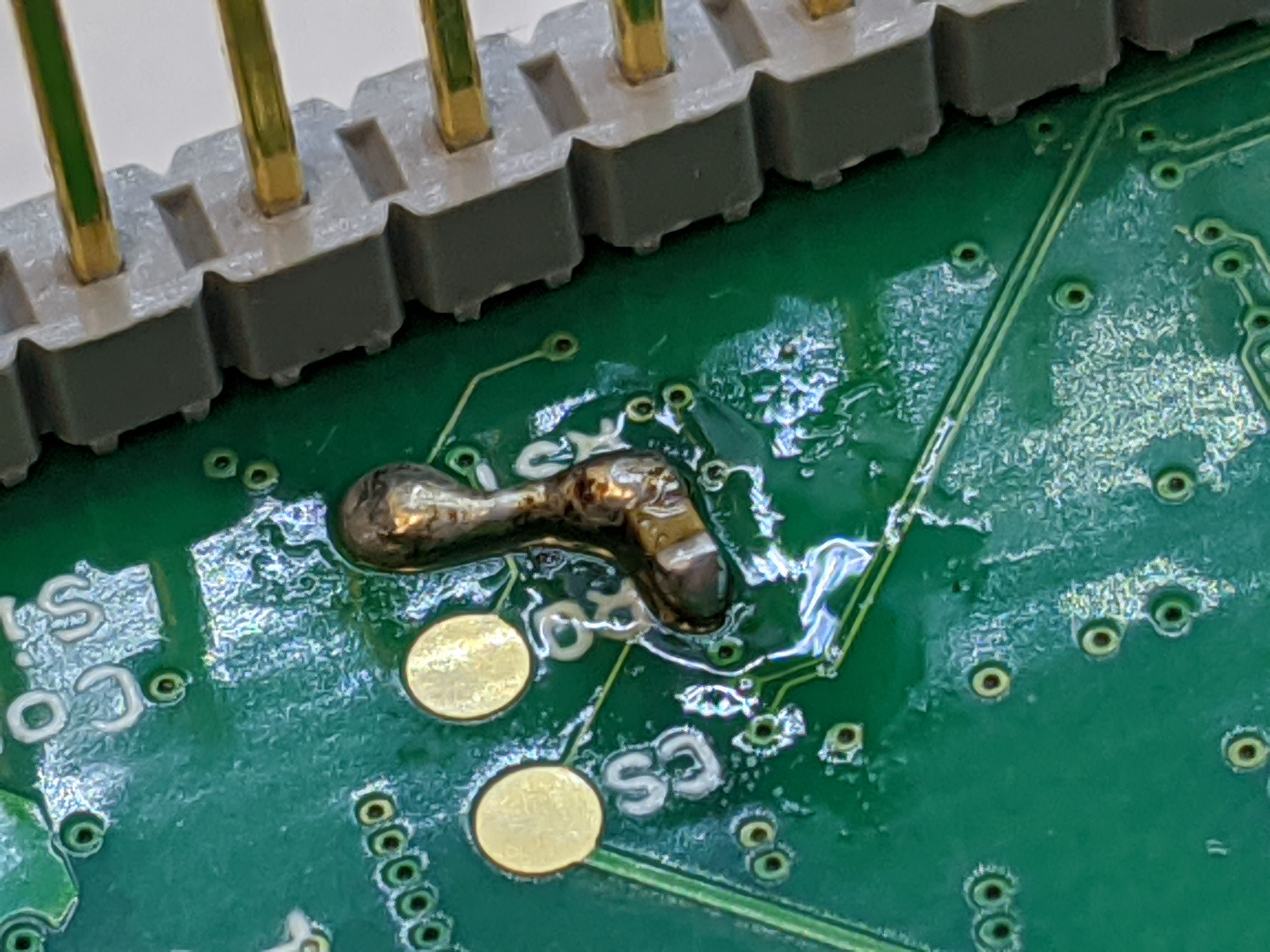
    Resetting something isn't particularly hard, the main problem I had to deal with was doing it as simply as possible because I have no space for anything fancy on this tiny board.  So I started out the simplest way I could think of.  Since the W5500 datasheet mentions that there's a 77K nominal pull-up resistor on the RSTn pin, I decided to just add a 0.1uF capacitor from this pin to ground.  The simplest reset circuit, the idea being that the RSTn would release with a little delay after power came on.

    I scraped the solder mask off a GND connected via and soldered a cap to it on the bottom of the board.

    It worked! :)  Then it didn't. :(

    The first time plugged in, the PHY came up correctly.  Then unplugging and replugging, it didn't.  What was going on?  I decided to measure the voltage on the cap, and found that it was still at 2.5V or so after the power was removed.  Discharging very slowly.  I decided to short the cap and plug it in, and the PHY came up correctly.  My cap was just not discharging when the power went away.

    It seems the pull-up "resistor" is actually a highly resistive PFET that isn't active when the chip is off.  This is a very common thing to do for pull-ups on chips, since FETs are much smaller than resistors on chips, and size equals cost.  But I had expected that the cap would still discharge through the ESD diode that typically goes from a chip IO to the positive power supply.  Turns out the W5500 has 5V tolerant IOs, which means the ESD protection has to be implemented differently (likely with zener diodes) and there is no diode going from the IO pin to supply.  Hence no discharge path for the cap on RSTn when power goes away, only self-discharge.

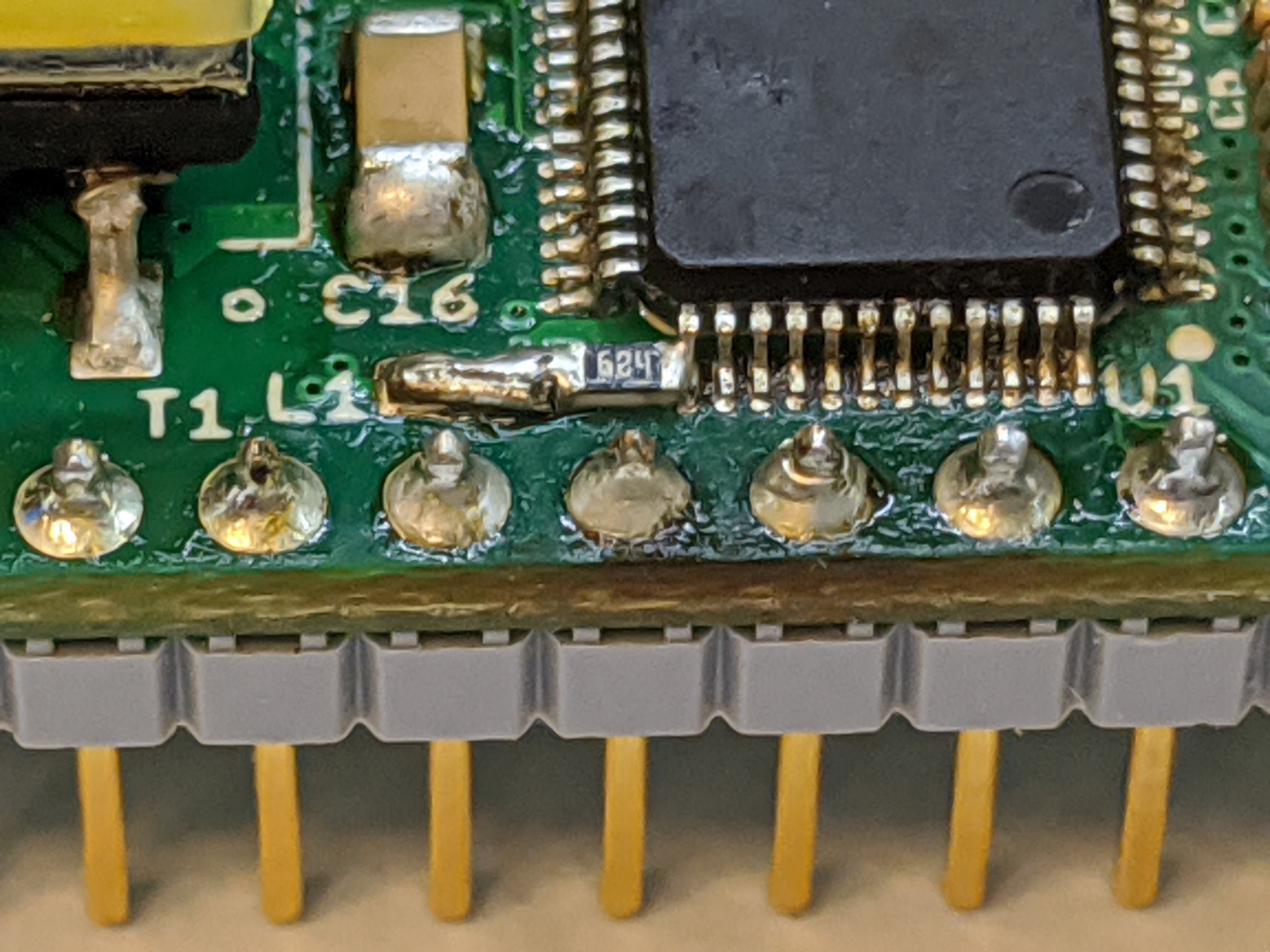
    Unfortunately this means adding another part, a diode or resistor.  Resistor hopefully, since it's smaller and cheaper.  I added a 680K from RSTn to VCC.  As I had been considering where I could possibly fit this parts, I decided to get rid of ferrite bead L1, since that seemed like the only good place for these extra parts to go.  Filtering the PHY power supply is a good thing, but likely not a make of break situation like the PHY not initializing correctly.  Space-wise, I was going to have one or the other and that made an easy choice, but I needed to check it would indeed work without the bead.

    Tried it and... success!  The W5500 would initialize correctly every time!

    I implemented this on both prototypes and it works good.  When L1 is gone, I can fit this new capacitor and resistor in 0402 package on the top side of the board where L1 was, keeping it single sided.  Time to implement all changes in a rev 2 PCB layout!

  • It works! Sort of.

    Patrick Van Oosterwijck12/17/2019 at 05:24 0 comments

    Getting the PoE to work

    Found some time to do more testing and tuning.

    The first thing I worked on was trying to get the low load control better.  I'm not so used to how primary side control flyback controllers work, the only other experience I've had with them had a chip that sampled the AUX voltage at a specific point in the PWM cycle.  Turns out the chip used here needs a continuous feedback signal from AUX and requires a good deal of filtering, more than I was doing.  I needed a bigger filter cap and things worked better once I hacked it on:

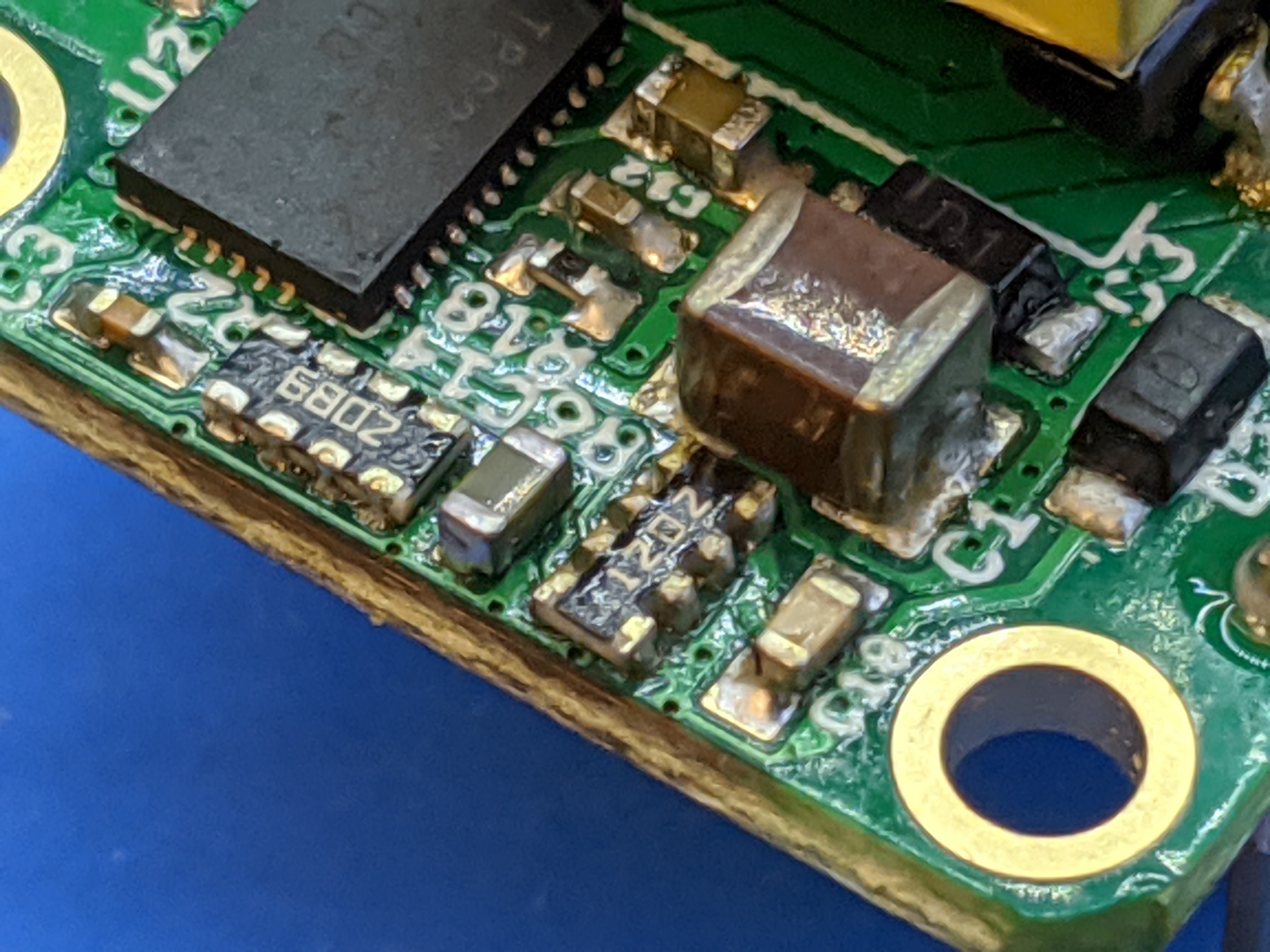
    C14 was a 0.1 uF cap, now it's a 4.7 uF.  Which (to keep things affordable and performant) requires a bigger package, 0603 instead of 0402.  It worked fine to hack it on here but I'll have to change the footprint.  I checked the layout and there's enough room to do so in a rev 2.

    Making this change made the control loop work better, but the output voltage would still go too high at no load and low load.  The AUX winding would stay nicely regulated but this was not reflected on the secondary at low load.  Primary side control works best with specially designed flyback transformers that have excellent coupling between the secondary and auxiliary windings.  I am using a cheap generic flyback with no such "expensive" requirements.  I don't really want to make the system more expensive for a use case that isn't really useful: there is going to be enough load if a Feather is connected.  We just need to make sure nothing breaks due to overvoltage when nothing is connected.

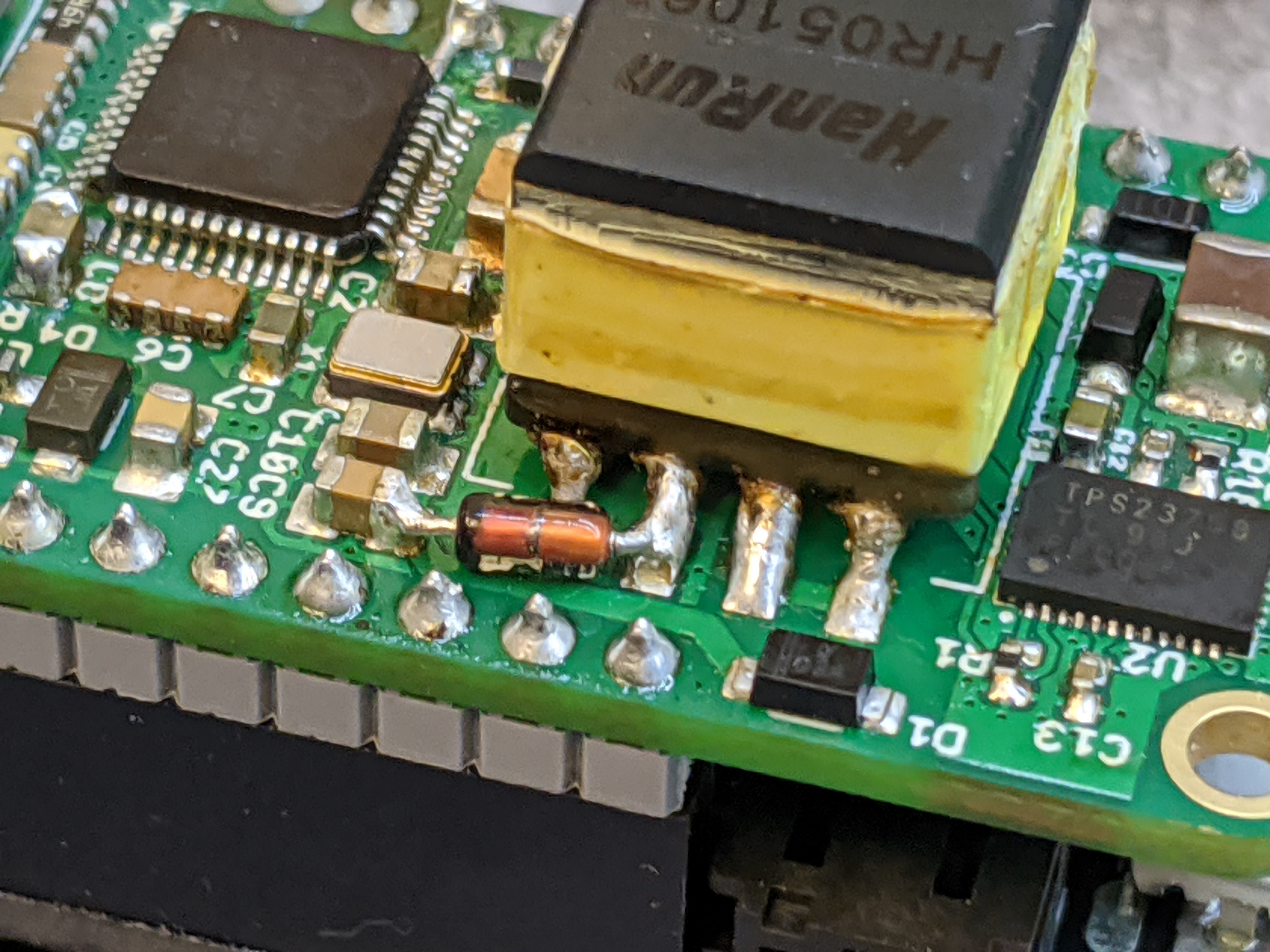
    If only there was a simple way to put on a load when the voltage gets too high... wait, there is of course!  A zener diode will do just that: no load when the voltage is low enough, drawing more and more current as the voltage increases.  This will be self-regulating: as the voltage increases, current will start to flow, which will present a load that will help the system regulate.  Since just a small load is enough to help the primary side regulation system regulate, the current through the zener and its power requirements will be minimal.

    Time to hack in a 5.6 V zener:

    Testing shows it works very well.  Under no load, the output voltage is ~5.5 V.

    So now that the power system was safe to hook up to a Feather, it was time to test that, and the Ethernet PHY.  Since the PHY is powered from the Feather's 3.3 V regulator, none of that had been tested yet.

    Getting the W5500 PHY to work

    A Feather was connected, successfully powered up from the PoE or USB, and could be programmed.  Following the directions from Adafruit I loaded the Arduino Ethernet WebClient example.  It didn't work.  The micro could communicate with the W5500, but it reported no cable was connected.  The LEDs on the Ethernet jack would light up in a pattern where one would turn on, then the other, then both went off.  Over and over.  I searched for an explanation of W5500 error codes but couldn't find anything.

    I tried all kinds of variations of the Ethernet side components but nothing made a difference.  Tried adding decoupling caps, nothing.  Eventually I decided to try to connect it up to a non-PoE cable running from USB and... it worked!

    I wasn't certain if this was good news or bad news.  More information and understanding is normally good, but this information seemed to indicate that there was a fundamental problem with the PHY when the PoE section was active!  Not something I liked to learn.  If the PHY just wouldn't work due to interference from the PoE, this project would be dead in the water.

    I did a bunch more stuff trying to limit interference, adding bulk caps, etc but nothing made a difference.  At some point I decided to try to reset the PHY.  This did work: the PHY would come up and the Ethernet WebClient example would correctly load the data!

    So, it looked like the PHY would work with an extra reset?  I decided...

    Read more »

  • Prototype build

    Patrick Van Oosterwijck12/11/2019 at 18:09 0 comments

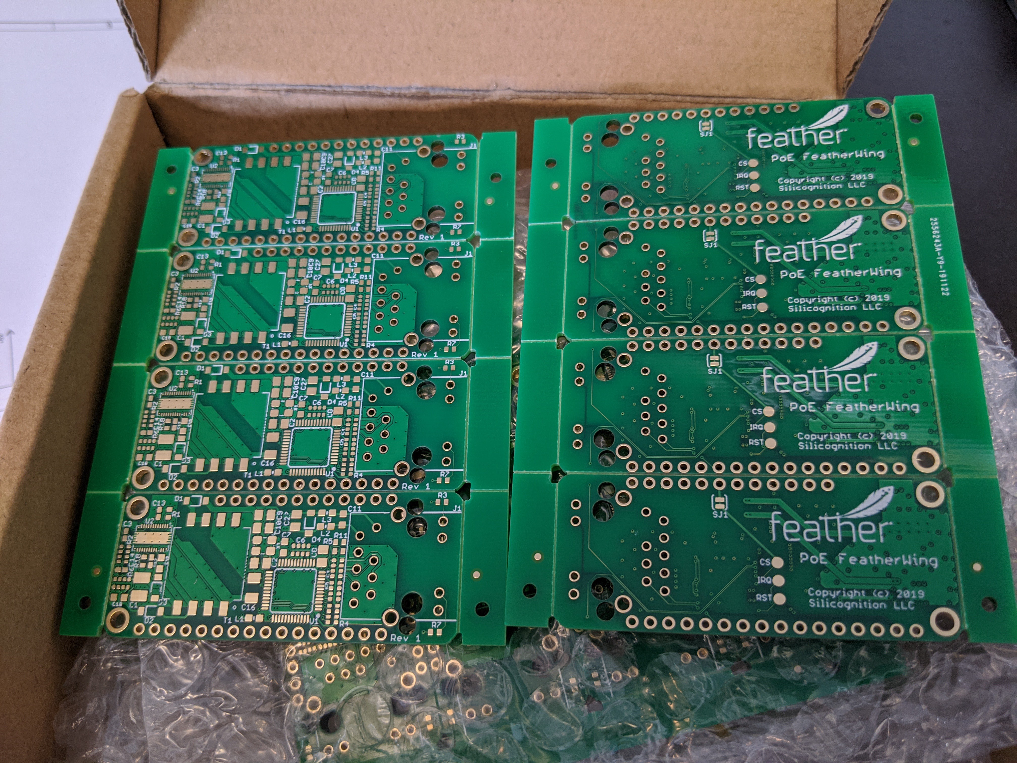
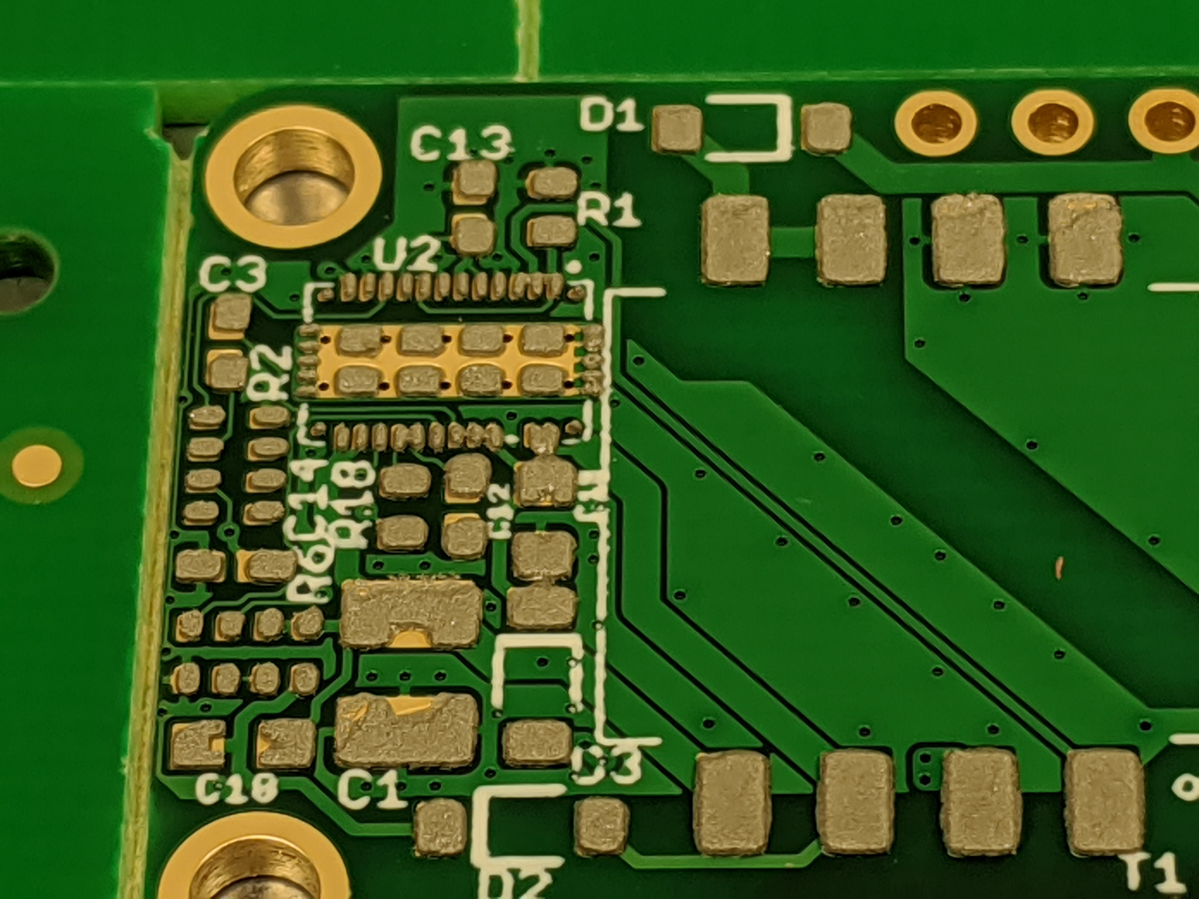
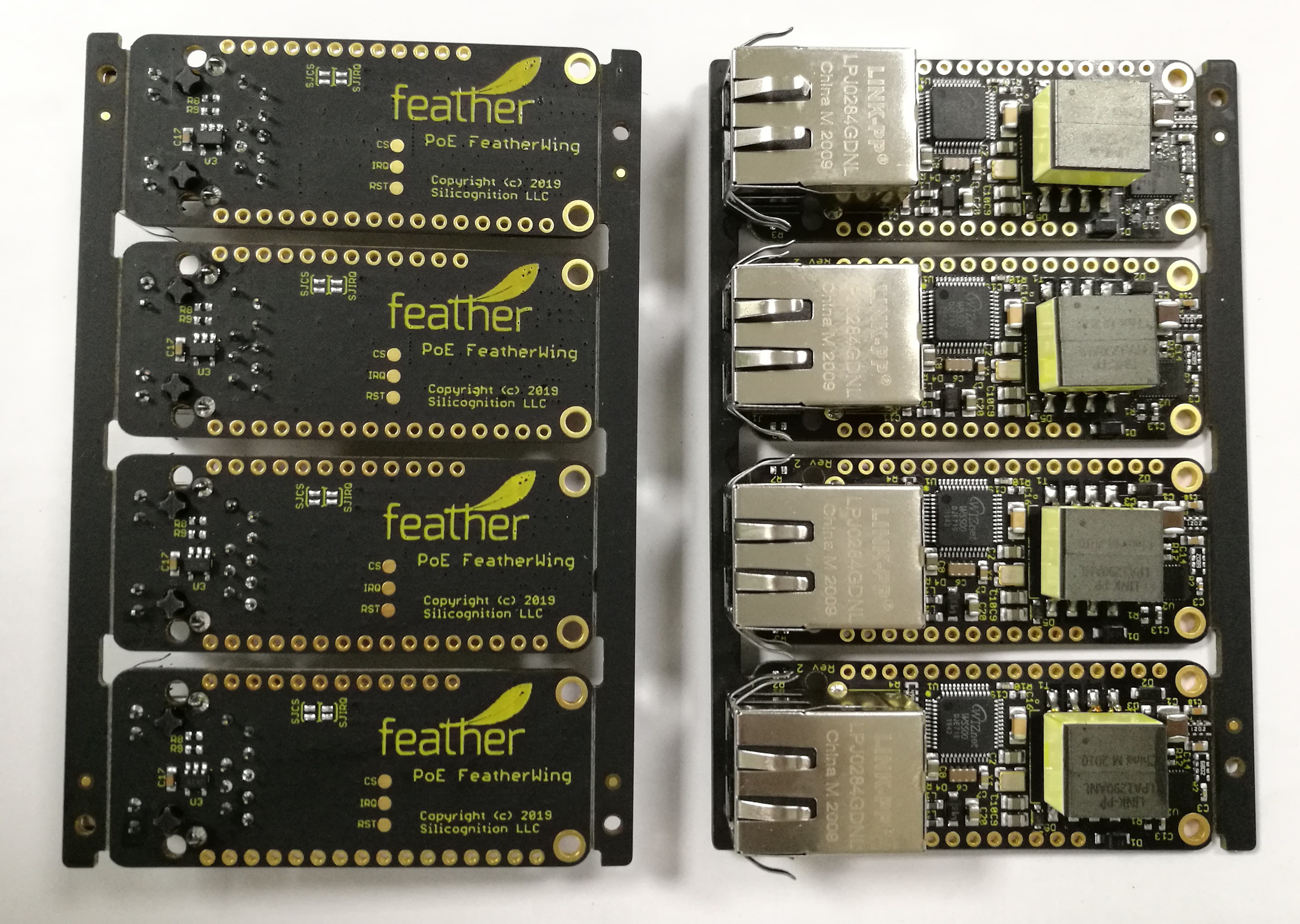
    The PCBs arrived from JLCPCB, looking excellent as usual:

    Time to build some prototypes!  So I headed to the Tinkermill to assemble two of them:

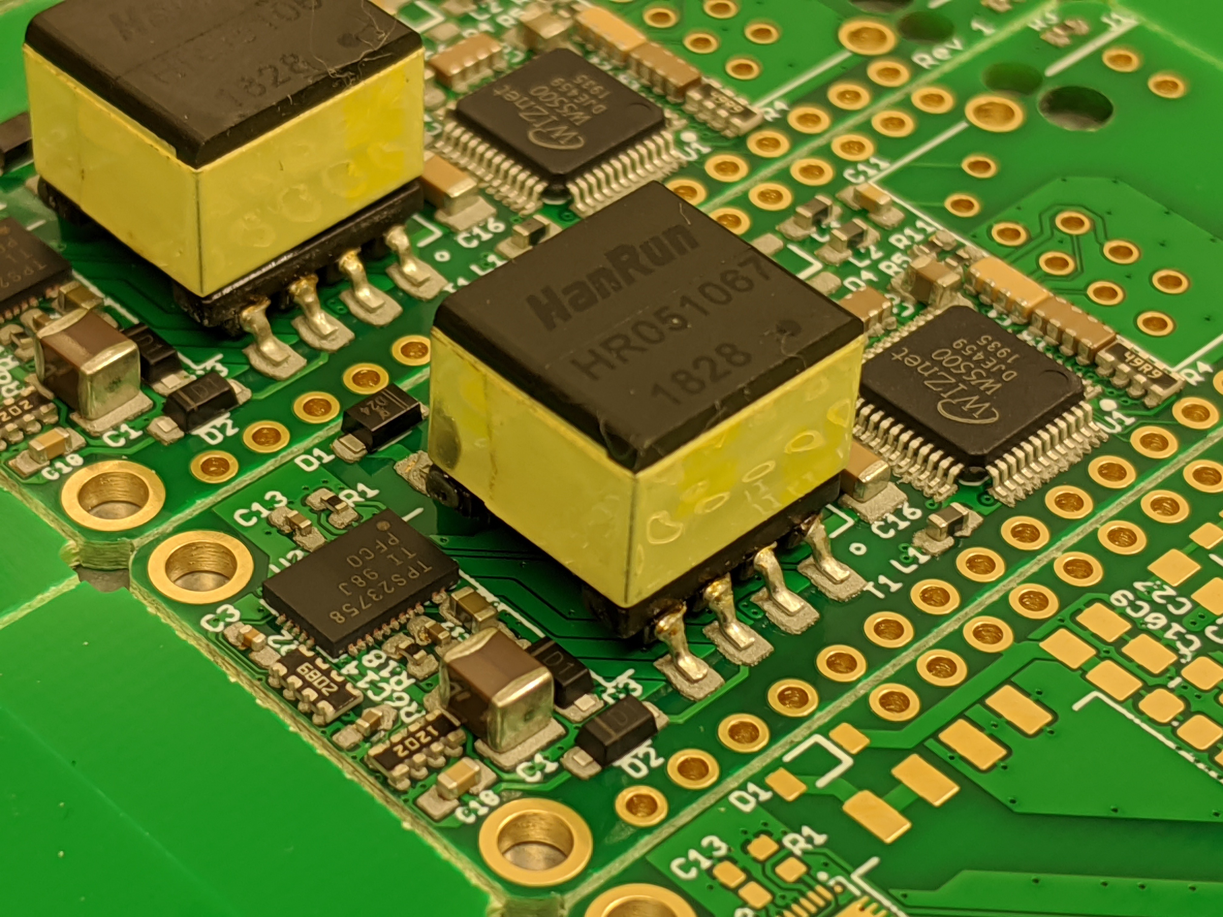
    Then through reflow:

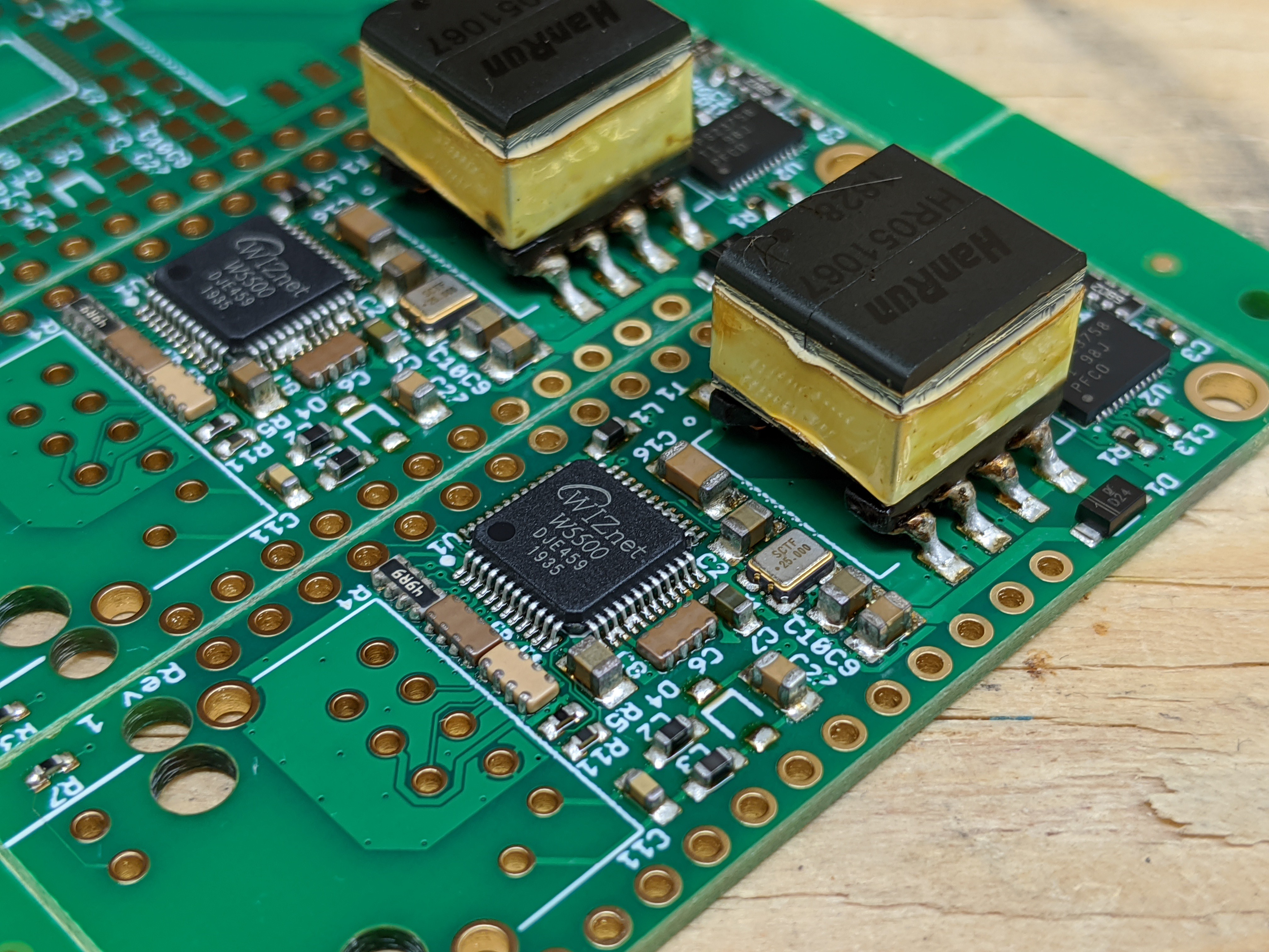
    Looks pretty clean, except for some shorts on the Wiznet W5500.  Also, odd that the tape on the flyback transformers was adversely affected, since it's supposed to be able to deal with lead-free reflow.  This was not the case with the professionally built LiFePO4wered/ESP32 prototypes that use the same flyback transformer, so I'm chalking it up to the lower quality desktop reflow oven I used.

    After cleanup and final through-hole assembly, I had some prototypes to test!

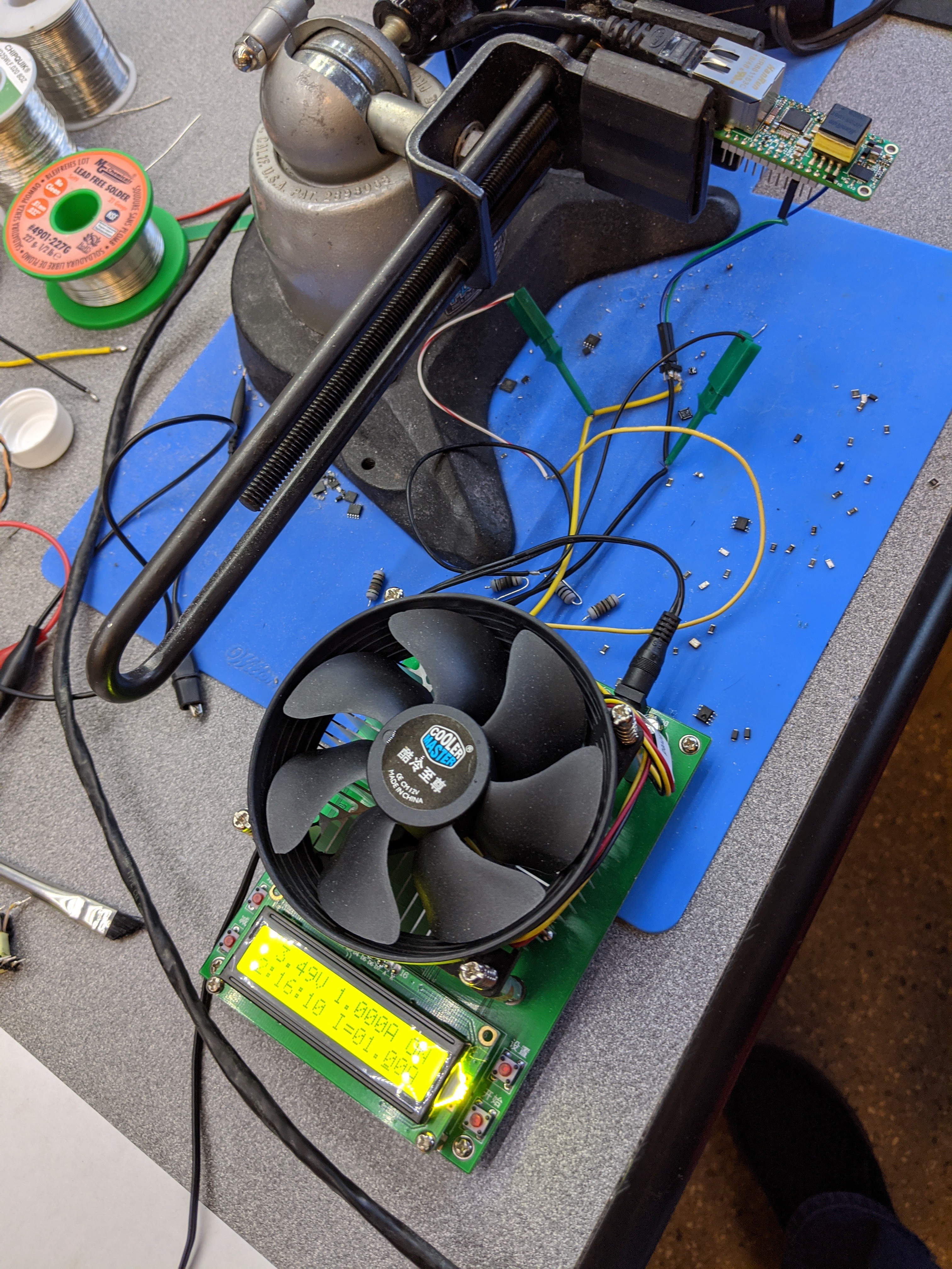
    First thing to try: do we get PoE power?

    The answer is yes, we are getting power!  The output voltage shown on the load is low because I'm measuring through the wiring, at the PCB the voltage was above 4 V at 1 A load.

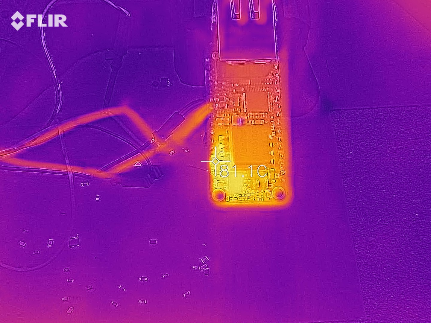
    Heat generation is reasonable, concentrated on the secondary side Schottky diode, while the PoE controller stays pretty cool:

    Oddly, things are worse at low load.  It looks like the primary side regulation control loop isn't working great and the output voltage would go way too high (around 15 V) at low and no load.  The picture below shows the situation with just enough load to keep things in control:

    Low load makes the PoE controller run way hotter.  Turns out this is because just like the output voltage went way high, the auxiliary voltage that feeds the chip does the same thing, and it was actually exposing the chip to out-of-spec voltages.  More testing at no load eventually killed the chip.

    Looks like I still have work to do to get this to behave properly. :)  Tuning the control loop tends to be a slow, labor intensive process of trial and error.  Still, I find this a promising start.

    Only after I get a stable output voltage will I hook this up to a Feather to test the Ethernet controller part, since this is powered by the Feather's 3.3 V.  Since most Feathers from Adafruit seem to use an AP2112 LDO, I'll have to make sure the PoE voltage doesn't go above 6 V since that is its maximum operating voltage.

View all 12 project logs

Enjoy this project?

Share

Discussions

Keenan Johnson wrote 02/03/2023 at 20:14 point

Hello! This project is excellent! Is there a 3d model available anywhere for us to design an enclosure around?

  Are you sure? yes | no

Patrick Van Oosterwijck wrote 02/03/2023 at 21:43 point
Hi Keenan,

No, unfortunately I don't have a 3D model...

I do accept contributed ones in case you create one. :)

  Are you sure? yes | no

Wong Chun Lung wrote 09/23/2022 at 13:57 point

Hi, will there be a version of the RJ45 jack faced up? like the M4 SHIM....

I using it in a 4 inch square touch panel project to talk to the touch screen by UART and communicate with the audio device by TCP.......

  Are you sure? yes | no

Patrick Van Oosterwijck wrote 02/03/2023 at 21:42 point
Probably not, because I'm using a highly integrated RJ45 jack that has the magnetics, Bob Smith termination and PoE rectifiers built-in.  Unless I can find a vertical RJ45 that has the same things integrated, it's not likely to be possible.

  Are you sure? yes | no

Rick M wrote 07/10/2022 at 02:29 point

I managed to fry my PoE board in a very strange way. I was troubleshooting an issue in which my device would work fine when plugged into a PoE switch I have, but not when plugged into another PoE switch (in both cases, it seems to power up and the code runs, but in the latter case, the networking doesn't come up properly).

Now for the damage: I was plugging and unplugging a USB connector into the M4 Shim, and I slipped and inserted it between the two boards. I don't know what I shorted out, but now when I plug in PoE, it powers up and runs, but something starts smoking. If I plug in only USB power, it runs without smoke. Very bizarre. I don't know what's smoking, and I soldered the two boards together, so it's hard to remove the shim to see what's going on.

I am sad.

  Are you sure? yes | no

Patrick Van Oosterwijck wrote 07/10/2022 at 02:44 point
Hi Rick,

Yes, that's a bummer!  But not too surprising that something could get killed that way.  Some parts of the PoE section have 48V while others are connected to chip pins that only are rated for low voltage.  The USB connector metal probably shorted something together that couldn't handle it...

When you power it from USB, the PoE section isn't powered, hence no magic smoke.

  Are you sure? yes | no

Rick M wrote 07/10/2022 at 05:23 point

What's odd is it still works! But immediately starts smoking. I've tried it twice (but not three times).

Prior to this damage, I had the issue where the networking wouldn't come up depending on the switch it was connected to. Any ideas there?

  Are you sure? yes | no

Rick M wrote 06/27/2022 at 06:01 point

Is there SSL support in the Ethernet drivers yet? I can't tell by looking at them, but last time I tried, I couldn't make SSL connections to MQTT servers or websites. What would it take to get SSL support?

  Are you sure? yes | no

Patrick Van Oosterwijck wrote 07/10/2022 at 02:47 point
Sorry I didn't see this sooner Rick.  Did you find out if SSL support is present in the Ethernet drivers now?  I assume you are using CircuitPython, this library seems to support SSL: https://github.com/adafruit/Adafruit_CircuitPython_MiniMQTT

  Are you sure? yes | no

Marc-Antoine Lalonde wrote 05/19/2022 at 05:40 point

That M4 shim is brilliant. Good work!

  Are you sure? yes | no

Patrick Van Oosterwijck wrote 07/10/2022 at 02:48 point
Thanks!

  Are you sure? yes | no

gjpehl wrote 01/28/2022 at 00:06 point

Hello.

I just assembled the POE ethernet featherwing and the M4 shim, and i've got some adafruit test code running- so far so good.

I want to write a program that publishes data to a server from a sensor connected to the M4, but the adafruit example code doesn't really seem to go into that much- any suggestions on a good way to start learning about how to do that?

Thanks in advance for any advice!

  Are you sure? yes | no

Patrick Van Oosterwijck wrote 02/25/2022 at 16:52 point
I have a couple of demos in this repo:

https://github.com/xorbit/PoE-FeatherWing-demos

Is that of help?

  Are you sure? yes | no

anon wrote 08/03/2021 at 22:18 point

Does this function with Arduino running at 3.3vdc?  Thanks in advance.

  Are you sure? yes | no

Patrick Van Oosterwijck wrote 08/03/2021 at 23:20 point
Yes, I think so if I understand your question correctly.  It's specifically made for use with Feather boards (running Arduino or CircuitPython or whatever), if you want to use Arduino form factor hardware instead it can probably be made to work as well.  It can provide power that the Feather (or Arduino board) can regulate to 3.3V and the W5500 logic and MAC chip all runs at 3.3V only, powered from the Feather's 3.3V supply.

  Are you sure? yes | no

anon wrote 08/04/2021 at 14:26 point

Yes, I did mean Arduino hardware.  Thank you for your response.  Great board!

  Are you sure? yes | no

Rick M wrote 08/02/2021 at 20:28 point

Can I change any components to get 5V (or even a bit more) out of this? I’m not worried about USB, but I need a solid 5V-5.1V for peripherals. 

  Are you sure? yes | no

Patrick Van Oosterwijck wrote 08/03/2021 at 16:15 point
It's difficult, because to keep the size tiny I employed several resistor arrays.  So if you change the resistive divider that determines the output voltage, you will be affecting the compensation network and switching frequency as well.

You can try to change R2 from a 4x68K to a 4x82K resistor array.  I think that should get to to 5V and above.  Note that regulation isn't great so the actual voltage varies with the load.  You may want to add an LDO to get a more stable 5V.

This is all theoretical!  I have not tried it myself.  Good luck and let me know if it works if you decide to try it. :)

  Are you sure? yes | no

Rick M wrote 08/03/2021 at 18:21 point

If you ever do a revision, I think it's important to provide just over 5V, and let the application deal with USB. Otherwise it can be very difficult to use a 5V peripheral. Even 12 V with an on-board reg would be great. Don't be afraid to use the bottom! I would also accept a longer board.

  Are you sure? yes | no

Patrick Van Oosterwijck wrote 08/03/2021 at 23:17 point
To be honest, the main goal of the PoE-FeatherWing was to be tiny, and provide power for a 3.3V Feather.  Concessions had to be made to make that happen.  It's not made to work with 5V peripherals.  For that, I have the much more capable #wESP32: Wired ESP32 with Ethernet and PoE, which can product very solid and well regulated 12V (with 13W of power) or 5V if you close a jumper.
Currently out of stock in most places but my CM is building more as we speak.

  Are you sure? yes | no

Rick M wrote 06/27/2022 at 06:01 point

Pity. That one is substantially more expensive, and isn't ARM-based.

  Are you sure? yes | no

xqdzn wrote 02/06/2020 at 22:37 point

Man this is very interesting! I've been looking for small microcontroller with PoE and Ethernet ability this whole time. And finally someone make it happen!

  Are you sure? yes | no

Patrick Van Oosterwijck wrote 02/14/2020 at 22:13 point
Thanks!

  Are you sure? yes | no

timonsku wrote 11/08/2019 at 22:51 point

Oh hey that's great! Glad you got around to it :)

  Are you sure? yes | no

Patrick Van Oosterwijck wrote 11/08/2019 at 23:18 point
Right! It only took more than a year. ;)

  Are you sure? yes | no

Similar Projects

Does this project spark your interest?

Become a member to follow this project and never miss any updates