Close
0%
0%

12bit Sound Reactive Neo-Ring

Programmable Sound Reactive Neopixel Ring

Similar projects worth following
This is a programmable sound reactive board with 12 full-color Neopixel LEDs, specially designed to be used as a wearable device or a gadget for other audio systems.

Electret condenser microphone converts sound into an electrical signal, which is then amplified by an op-amp. MCU reads this signal and generates a light pattern on Neopixel LEDs.

The round plate has 45x45mm with a thickness of 1mm (5mm assembled), making the final assembled board weights only 5 grams, small enough to be incorporated into portable devices or wearables.

You can see how it works in this video


MCU

Main microcontroller is a mainstream STM32f070 32-bit ARM Cortex-M0, operating at 48MHz, with 32Kb of FLASH memory and 6Kb of RAM. 

The embedded firmware uses three different peripherals from the micro: 

  • 12bit ADC to read the sound signal in continuous mode.
  • TIMER configured to work at 800KHz to send PWM signal to the LEDs with the NRZ protocol.
  • DMA, used for the ADC acquisition and to send data to the timer channel as a PWM signal, so the CPU is unloaded as much as possible during all the process.


Sound acquisition

it uses an omnidirectional electret microphone of 6x2,7mm with -50dB sensitivity working at frequencies from 100Hz to 10KHz. Signal is amplified with an op-amp that features rail-to-rail input and output, with a 6MHz gain-bandwidth that can be adjusted with an SMD variable resistor.


LEDs

The LEDs are WS2812 chips in a 5050 package, and I use two different versions according to the needs of each project:

  • WS2812B for a max brightness results, with an overall consumption of 380mA.
  • WS2812C for a much long run on battery powered devices. Brightness is reduced to one-third of the B version, making overall consumption reduced to 180mA.


User Button

Button allows you to switch between different light patterns:
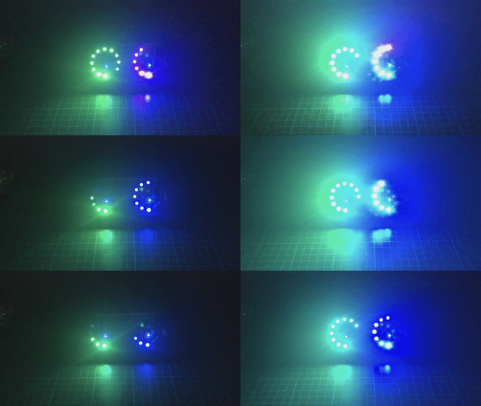
Sound pressure Gauge
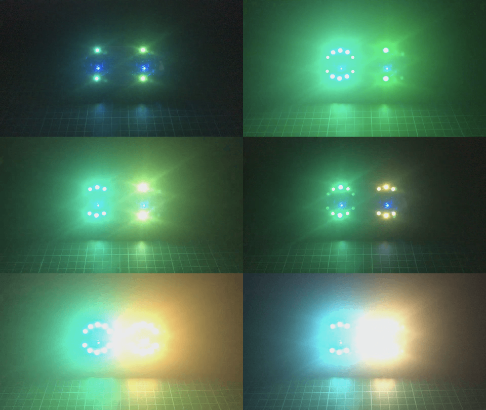
Half ring mirrored
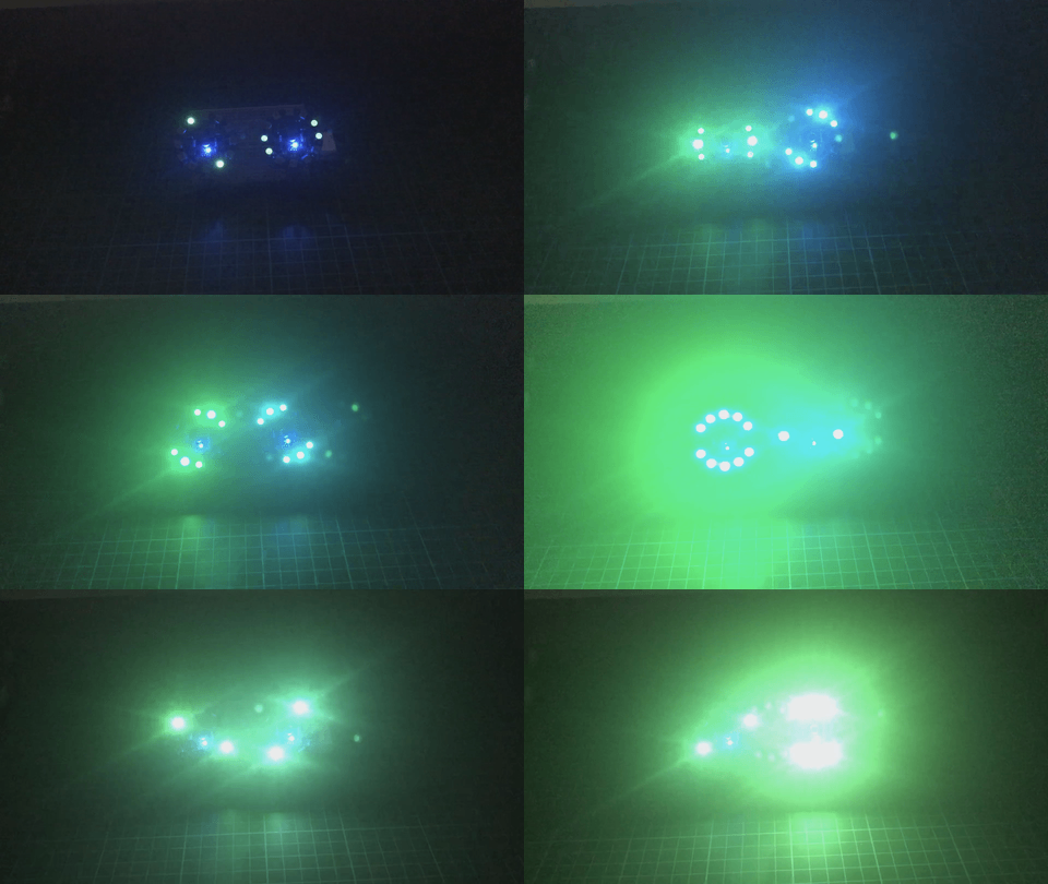
Half ring with rotation

With a hold-press, you can adjust the max brightness. Visit the github project page for more info.


Voltage ratings

There is a LDO voltage regulator to adjust input voltage to the 3.3V required by MCU. It accepts a max input voltage of 5.5V, but it must be down to a range of 3-4V for proper communication with LEDs, so a LiPo one-cell (1S) is a good option. 

A Schottky diode protects the system from reverse polarity.


Connectors

The board exposes I2C pins to acquire data from external sensors, SWD pins for MCU programming / debugging, Audio OUT pin to access the op-amp output, and WS OUT pin to attach more LEDs to the system.

12bit_Neo-Ring_BOM_v1.1.xlsx

Bill of Materials

sheet - 12.32 kB - 10/03/2020 at 20:45

Download

Adobe Portable Document Format - 139.88 kB - 10/03/2020 at 11:28

Preview
Download

  • 1 × STM32F070F6P6 MCU Cortex-M0
  • 12 × WS2812x Neopixel LED
  • 1 × GS8632C-SR Low Noise OpAmp. 6MHz Gain-Bandwith. Rail-to-rail input and output
  • 1 × Electret mic 6x2.7mm package with -50dB sensitivity

  • Desktop Lamp

    Manuel Alfonso03/06/2022 at 12:44 0 comments

    I've used two ring boards to create a desktop lamp. 

    The code has been heavily modified to integrate the new spectrum analyzer mode, in which the LEDs react according to frequency from 20Hz (led at 12 o'clock) to 2kHz ( 11 o'clock). Colors also been improved to perform more changes based on sound rhythm.

    You can check the updated code at the github repo.

    More info on the project page: https://hackaday.io/project/184291-pilot-sound-reactive-neopixel-lamp

  • Graphic Spectrum Analyzer

    Manuel Alfonso03/11/2021 at 00:03 0 comments

    Testing how well performs the board with a more complex operations. 

    I've implemented a spectrum analyzer to display the different frequencies on a 0.96" OLED display connected to the Neo-Ring I2C port. Also, LEDs react to that frequencies.

    The MCU limitation in terms of memory and power (no FPU) do not allow to use DFT or FFT transformations, even less DSP libraries. Fortunately I found a routine that implements FFT transformations with fixed-point short integers. Also I've used an integer square root implementation from here.

    I choose to focus on the most common frequency range with piano music, up to 2kHz, so the audio sampling rate is configured at 4kHz (Nyquist's theorem).

    I have to make some adjustments in the source code to integrate it correctly with the rest of the Neo-Ring display modes. When done, I'll update the source code repository.

    Comments and suggestions are welcome!

View all 2 project logs

Enjoy this project?

Share

Discussions

Similar Projects

Does this project spark your interest?

Become a member to follow this project and never miss any updates