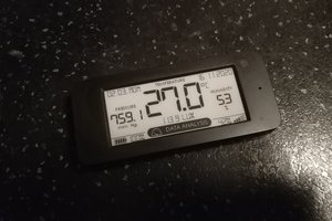
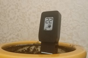
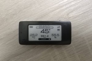
Greetings to all Hackaday readers! In today's article I will talk about my DIY project from a series of devices with displays on electronic ink (e-ink). The device in question is a wireless multi sensors device with a 2.13 inch e-paper display. The device can be equipped with an SHT21, HTU21D, SI7021 temperature and humidity sensor, a BME280 temperature and humidity sensor, a BMP280 atmospheric pressure sensor, and a MAX44009 light sensor. The device is powered by one CR2450 battery. But nothing prevents soldering a holder for CR2430 or CR2477 batteries on the device.
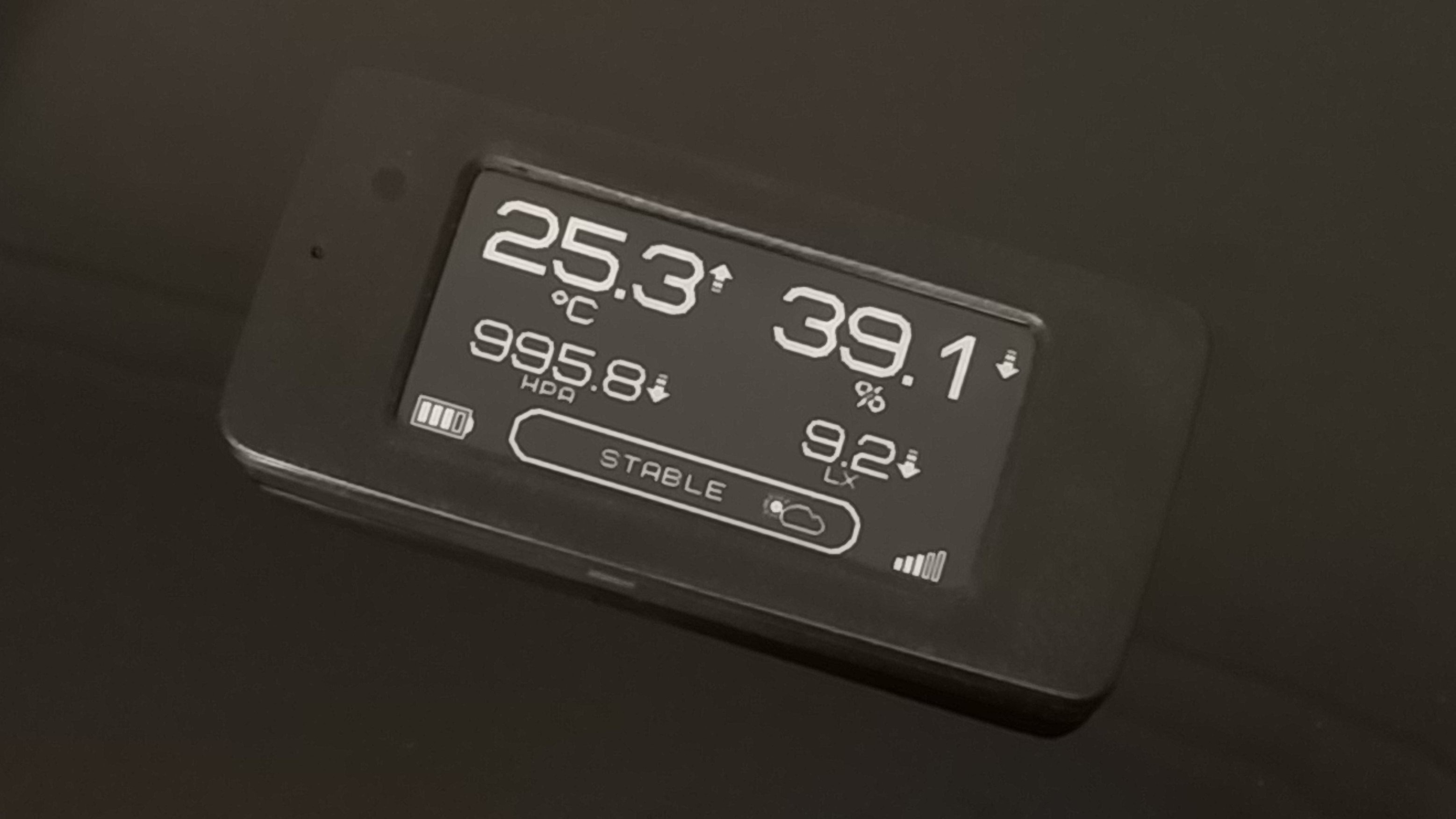
The project of a sensor with an e-ink display measuring 2.13 inches began a long time ago. The first prototype was made over a year ago. That first version ran on two cr2450 batteries and had a stabilized power supply. Over time, the project was changed and optimized, the size decreased, the radio modules and sensors changed.
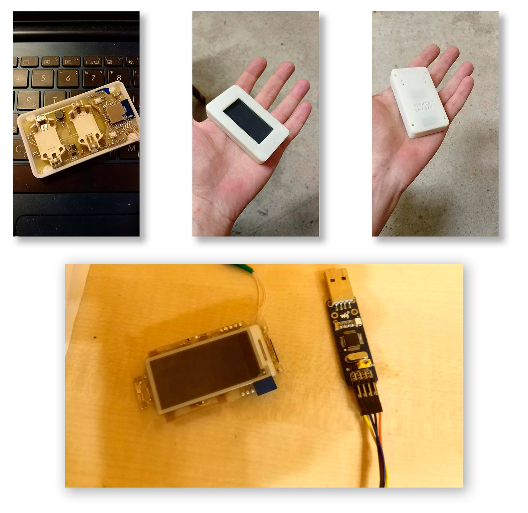
The pcb of the final version of the sensor has dimensions of 72 mm * 31 mm, the thickness of the PCB is 1.2mm. The dimensions of the sensor in the housing are 76mm * 35mm * 12mm.
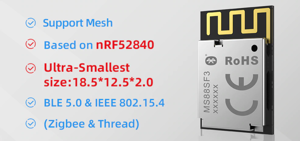
The device works on the nRF52840 microcontroller, the radio module MS88SF3 from MINEW is used. The module does not have side soldering pads, they are located at the bottom of the radio module. This feature was a little "annoying", but the eyes are afraid, and the hands are doing. As a result, the module is simply soldered with a hairdryer (I warmed the device board on which the radio module was installed from below).
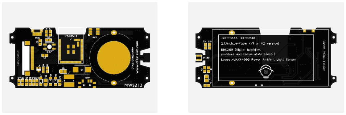
The device has two modifications of the PCB. In modification "A" a BME280 sensor and a LED are installed on the device, in modification "B" a light sensor, temperature and humidity sensors SHT21, HTU21D, SI7021 are added, the ability to install a BMP280 sensor is added, protection against polarity reversal on the transistor.

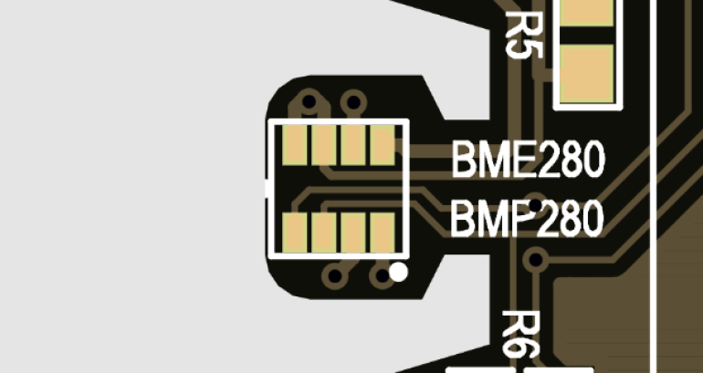
In modification "B" the place for soldering sensors BME280 and BMP280 was made universal, BMP280 is perfectly installed in place of BME280. I made this change already in the last revision of the second version of the sensor. The reason was the sharp rise in the price of BME sensors (on average by 70% over the past two months). Now it is possible to replace the BME280 functionality by installing BMP280 + SHT21 on the board (the BMP series does not rise in price yet). If anyone knows the reason for such a rise in prices for BME sensors, tell us about it in the comments.
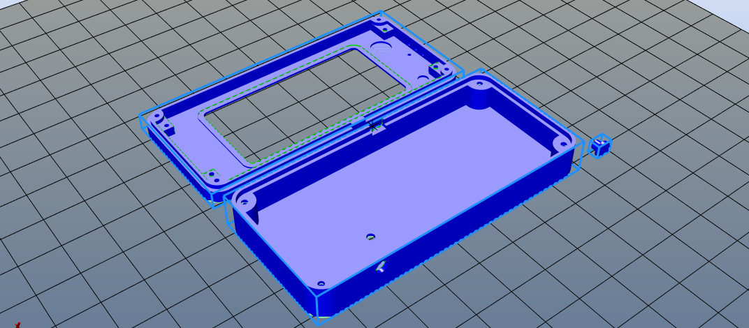
The sensor body was printed on an FDM 3D printer. After printing, the body was additionally ground and polished. For the LED in modification "A" and the light sensor in modification "B", there are recesses on the inner side of the upper part of the housing for subsequent drilling. I filled the drilled holes with polymer resin for the SLA printer.
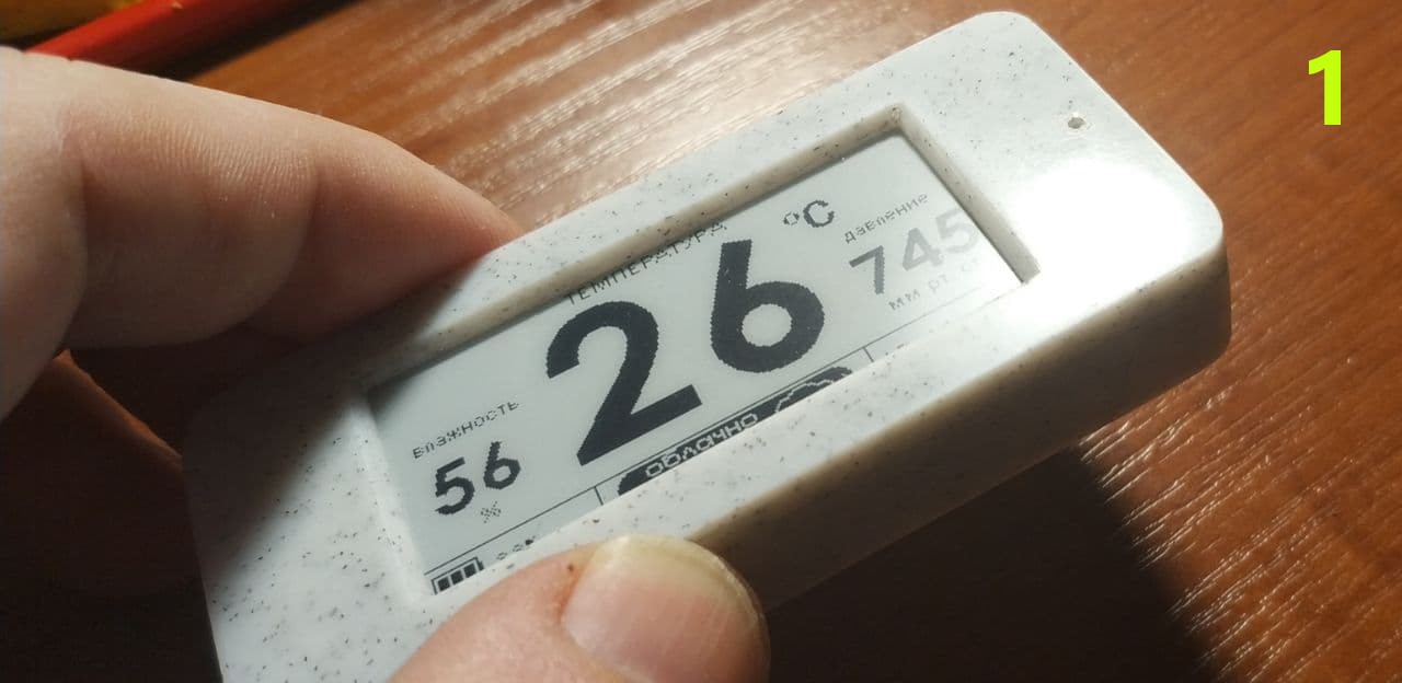
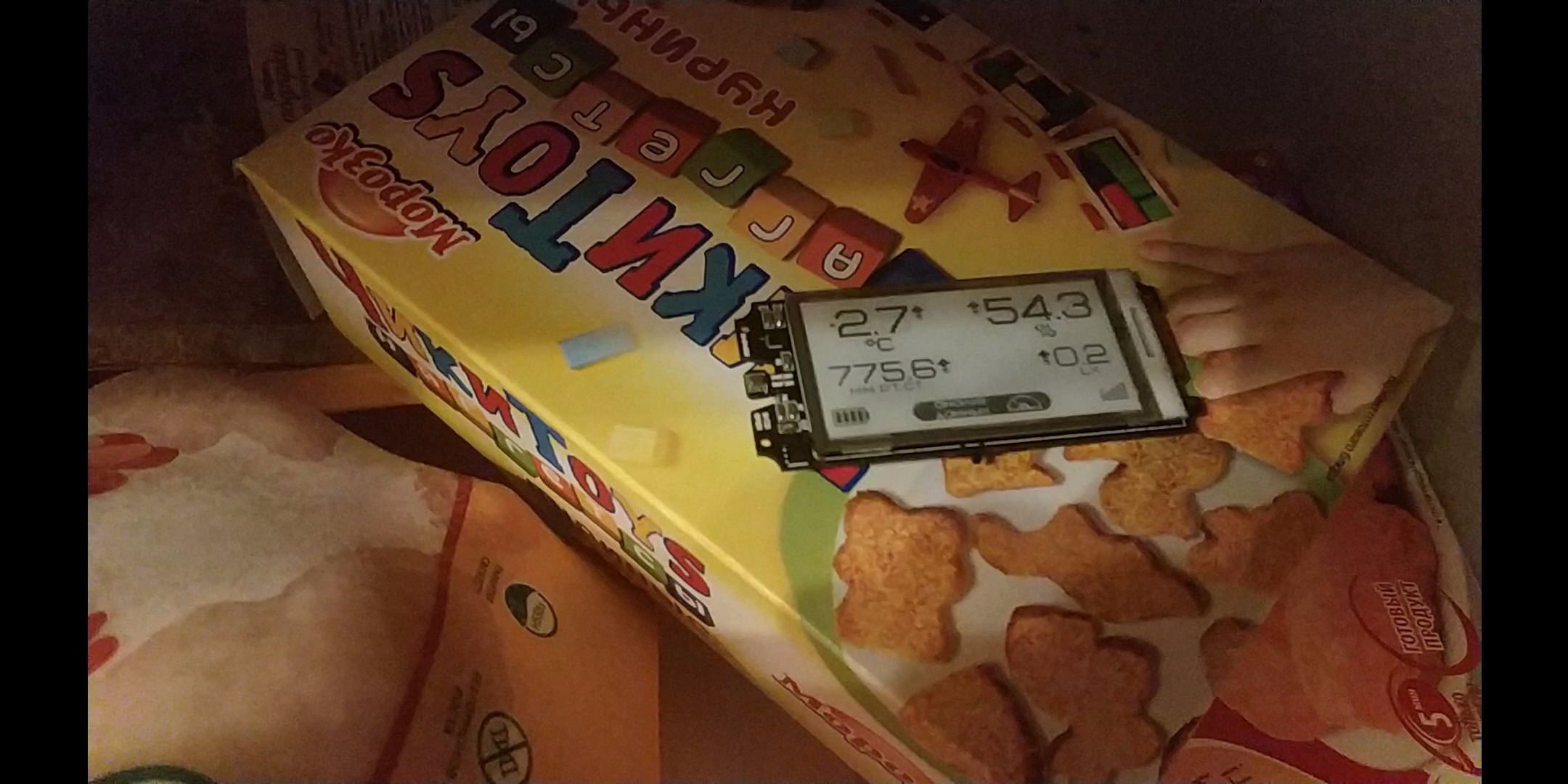
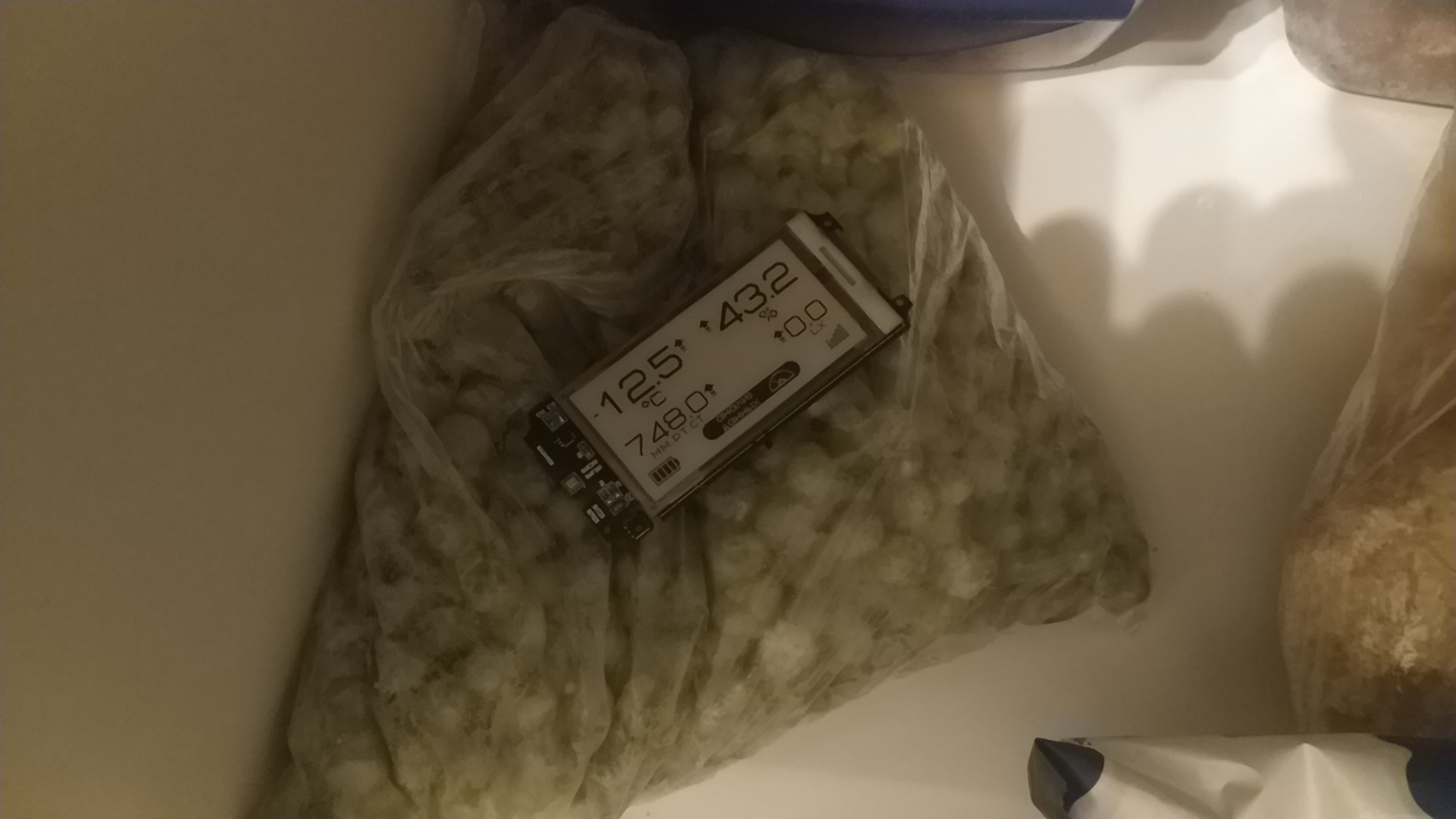
The device program was written for the open source project MySensors. The sensor displays data from sensors, battery charge, signal level, weather forecast for the next few hours. Next to the data from the sensors, the direction of change of values is also displayed by arrows. There were several interface design options, options 2 and 3 are available on my github.
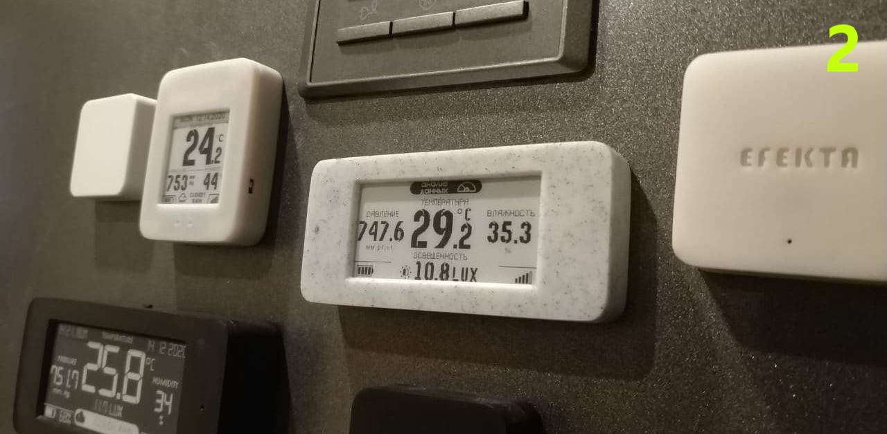
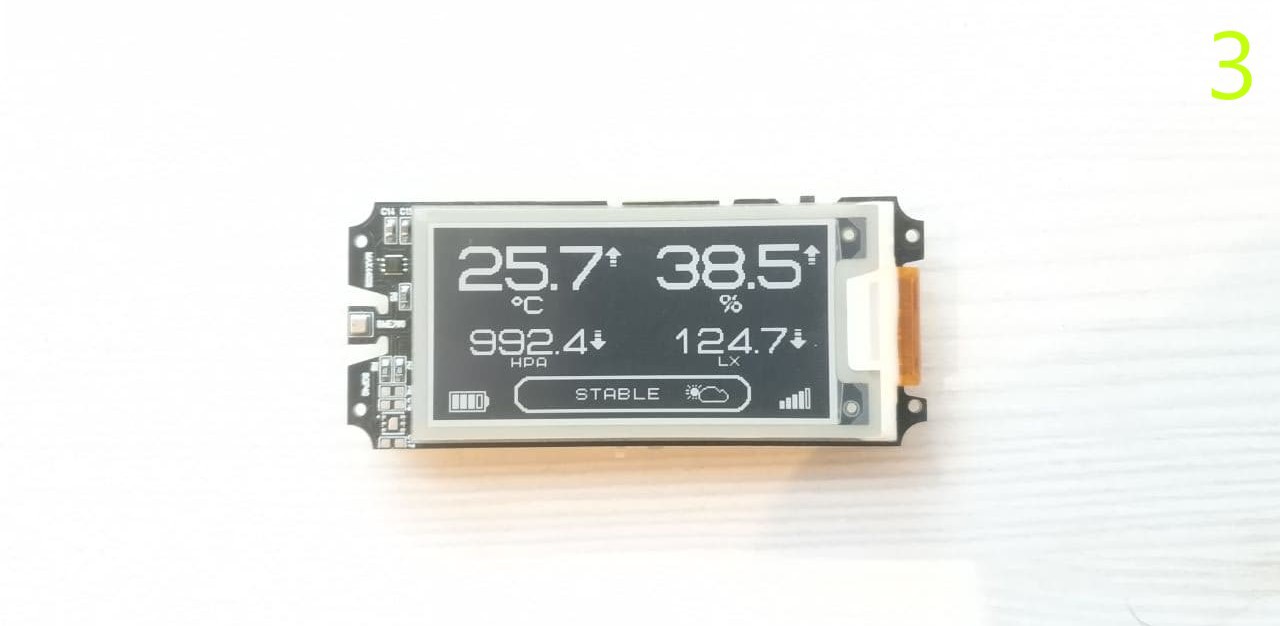
It is possible to invert the screen by pressing a button. The functionality of a simple menu with the following items has been added to the button: color inversion, device configuration, device presentation, sensor reset. In the configuration mode, the sensor listens to the air for 20 seconds, at this time it is possible to send configuration commands to the sensor from the Smart Home controller: changing the interval for sending data from sensors (from 1 minute to 1 hour in increments of 1 minute), changing the interval for sending data about battery status and signal strength (from 1 hour to 24 hours). In presentation mode, the device sends data about itself (name, firmware version) and sensors to the Smart Home controller, and makes a request about which system (metric or imperial) the network operates in. It also sends its configuration settings.
When working in a radio network,...
Read more » Andrew Lamchenko
 Rohan Menon