1. PERSEUS-68
When I was 16 years old and personal computers did not yet exist in the world, I was determined to complete a computer on my own by 1980, when I would have turned 20. The computer I built in 1980 to achieve this goal was the PERSEUS-68. The appearance of this computer is shown in Fig. 1. The CPU is a Motorola MC6802 with a system clock of 1 MHz. The RAM (MC6810) with a capacity of 128 bytes mounted on the board in addition to 128-byte CPU built-in RAM. The enclosure is made of aluminum angle, and it also serves as a card rack for the printed circuit board. The board is a universal board and wiring was done by soldering.
Programming is a DMA method that stops the CPU and releases the bus. This is based on an article in the book [1]. Address and data are set in binary by toggle switches on the panel, and data is written to the RAM when the write switch is pressed. The address bus is 16 bits, of which the lower 8 bits are set on the panel and the upper 8 bits are set with the DIP switches on the board on the side of the chassis. In addition to normal program execution, single-step operation can be performed by pressing the switch.
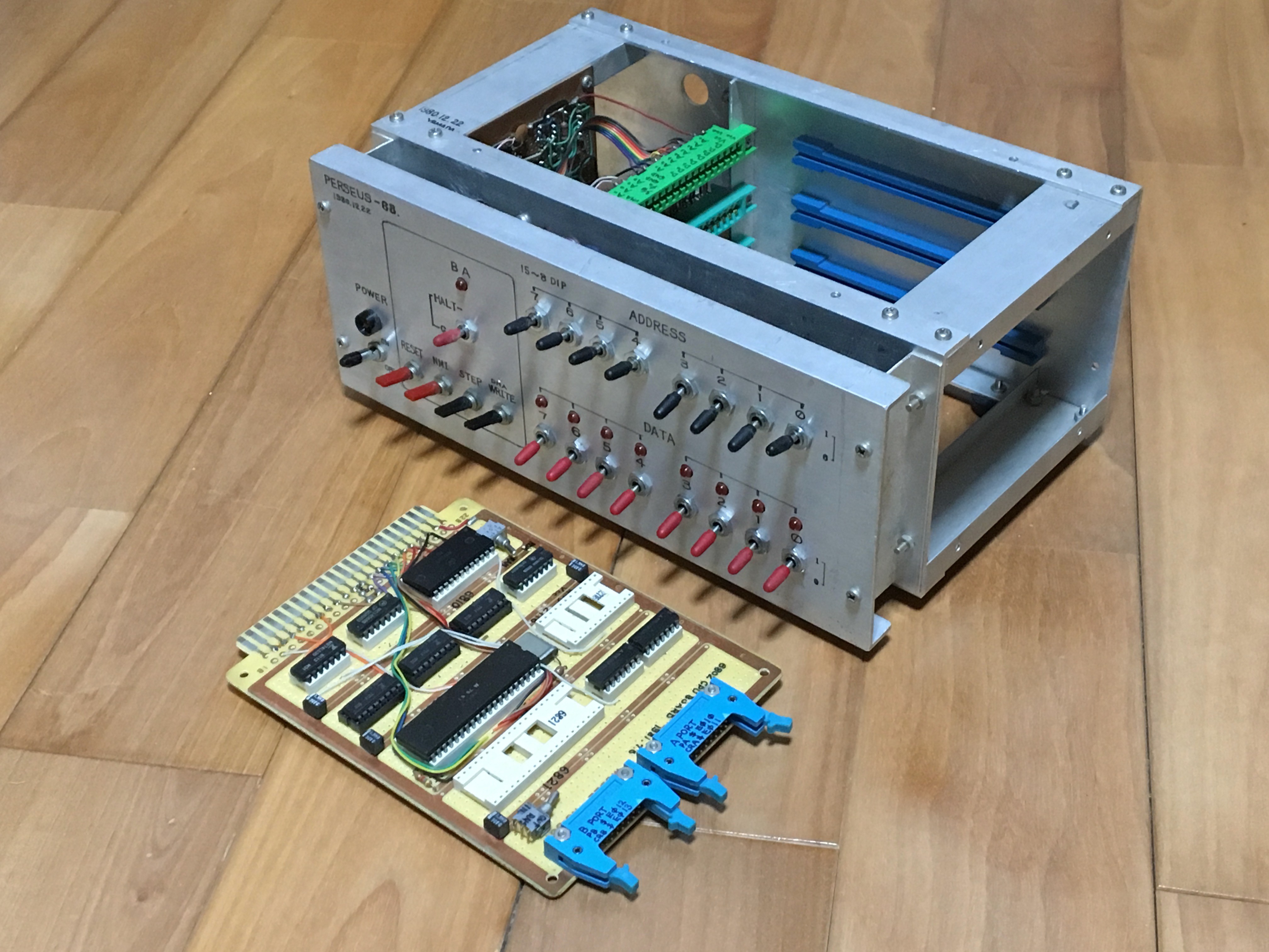
Fig. 1 PERSEUS-68
After this, I was able to complete the hardware testing of a serial interface board with expansion memory and a video interface board, that I built myself to add to the card slots. However, there was an inconvenience with this computer. It did not have a function to display the execution address during single-step execution. This made it difficult to debug the program because I could not see whether the instruction execution was progressing correctly or not. Therefore, I was only able to run software on this computer, such as a machine language test program of a few dozen bytes. After PERSEUS-3 in 2007, I have installed LEDs that displays the execution address in binary when a single-step is executed.
2. PERSEUS-88
I built this PERSEUS-88 myself in 1982. Figures 2 and 3 show the appearance of this computer. The CPU was a Fujitsu MB8870 running at 1 MHz system clock. This CPU has some instruction extensions to the MC6800. Four HM6116 SRAMs were mounted to make 8kB.
This PERSEUS-88 does not have DMA programming and single-step execution capabilities. The computer was operated by using a monitor program called MIKBUG contained in the MC6846 from a serial terminal. The dump list of the floating-point BASIC interpreter for the 6800 that was published in a magazine was typed into the serial terminal and it was able to operate it. Data was saved and loaded by connecting a cassette tape recorder to the audio interface.
An EPSON MP-80 dot impact printer was connected to the parallel interface. The single character output routine of the interpreter was modified so that all characters sent to the serial terminal are also sent to the printer when the printer output flag is detected. This flag was defined in 1 bit of the other parallel port and operated ON/OFF with a red toggle switch on the panel. The board was a universal board and wiring was done by soldering.
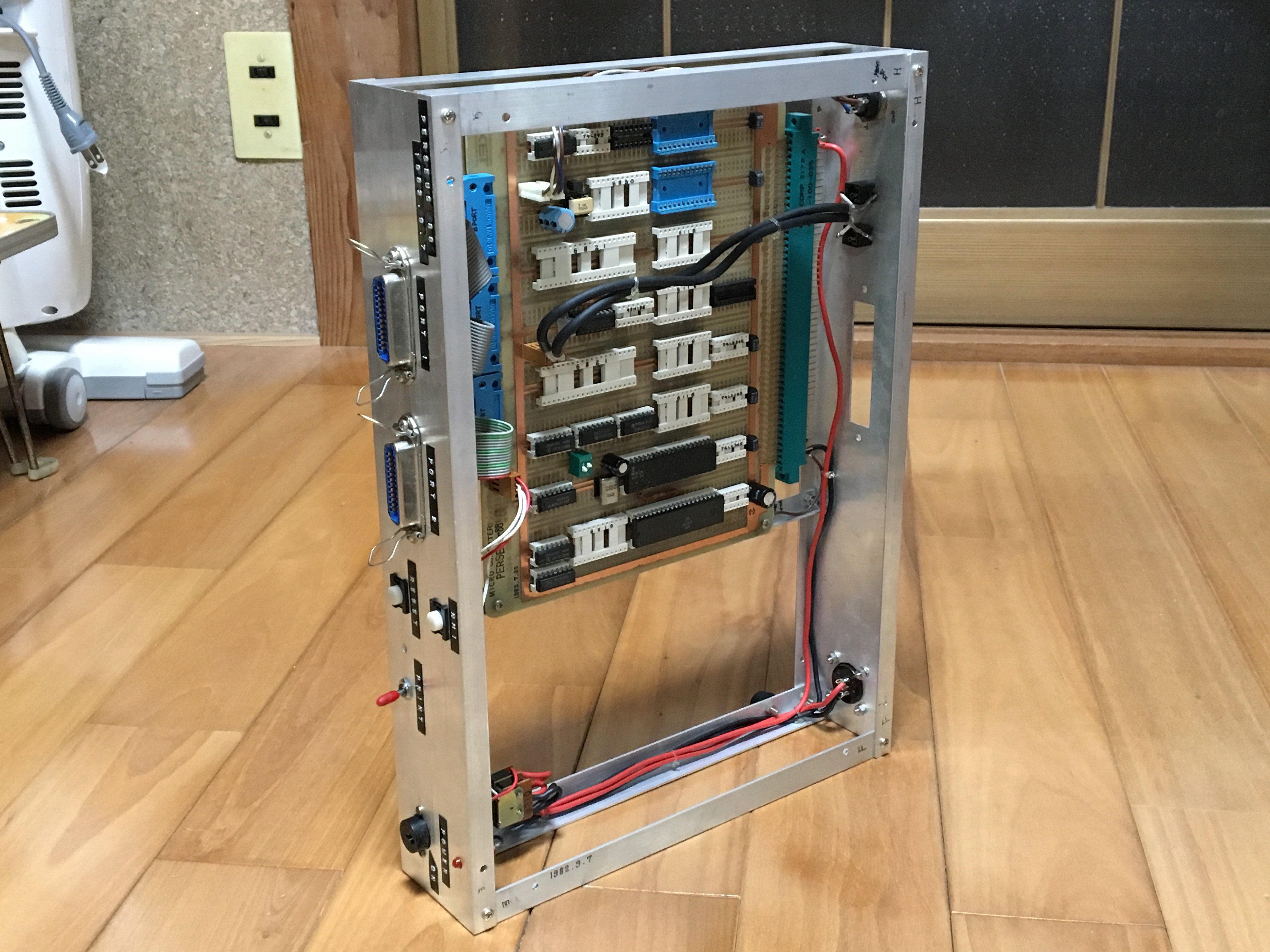
Fig. 2 PERSEUS-88
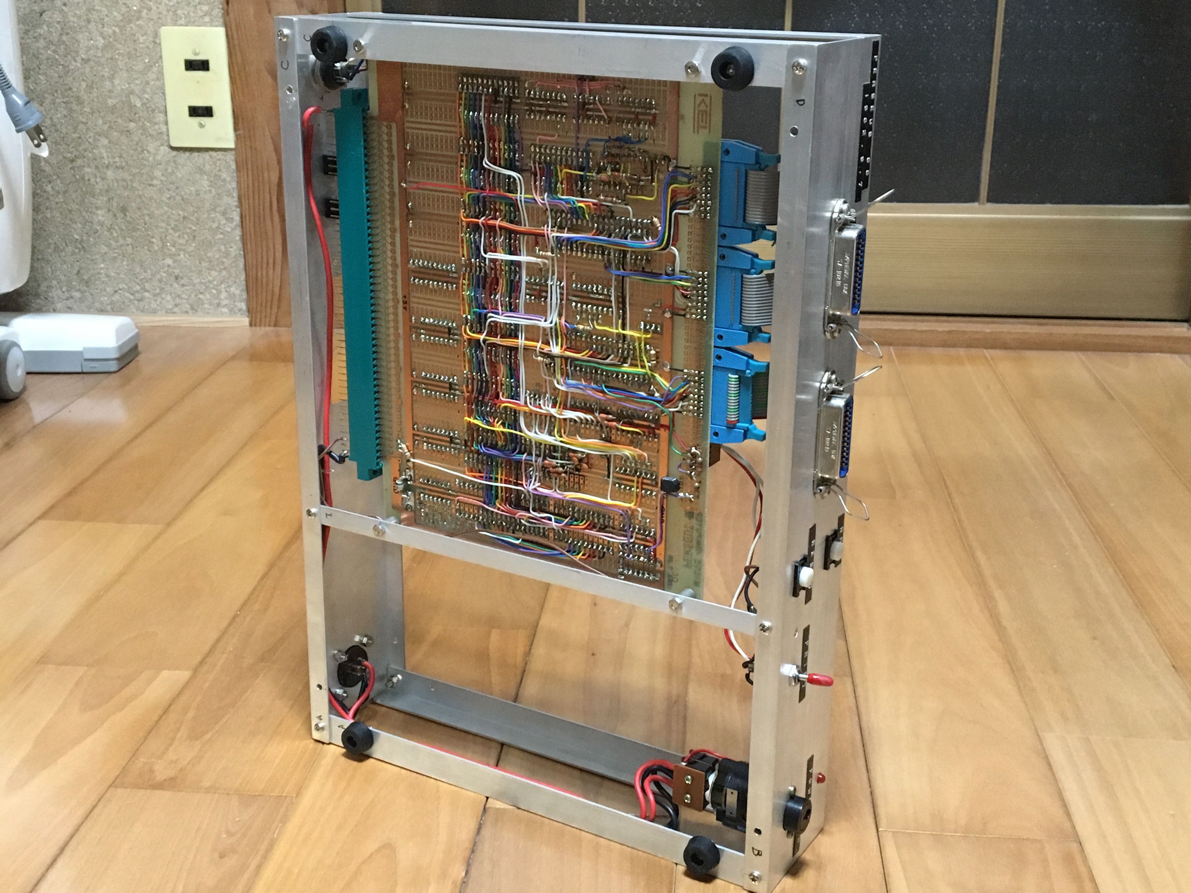
Fig. 3 Bottom view of PERSEUS-88
3. Serial terminal
In 1982, a serial terminal was also built for PERSEUS-88 operation. This serial terminal GEMINI-230 is shown in Figures 4 and 5. The keyboard was a parallel interface type sold by ALPS in Japan at the time. The control of the transmit/receive buffer memory and the generation of the video synchronization signal were performed by a commercially available dedicated LSI SFF96364. The video output could display 64x16 characters on a CRT monitor. The character generator IC was made by writing font patterns on a PROM 2716. An UART IM6402 was used for serial communication. The communication standard is the current loop method of 300 bps or 1200...
Read more » Mitsuru Yamada


 Keith
Keith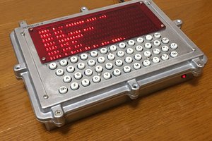
 BladeRunner
 Denver
I enjoyed reading how your "way back" projects lead to more recent projects that you've shared here, and seeing that your elegant construction style goes all the way back. I'm a little puzzled by your choice of English for labels. And note that your hand lettering looks much better than Dymo tape!