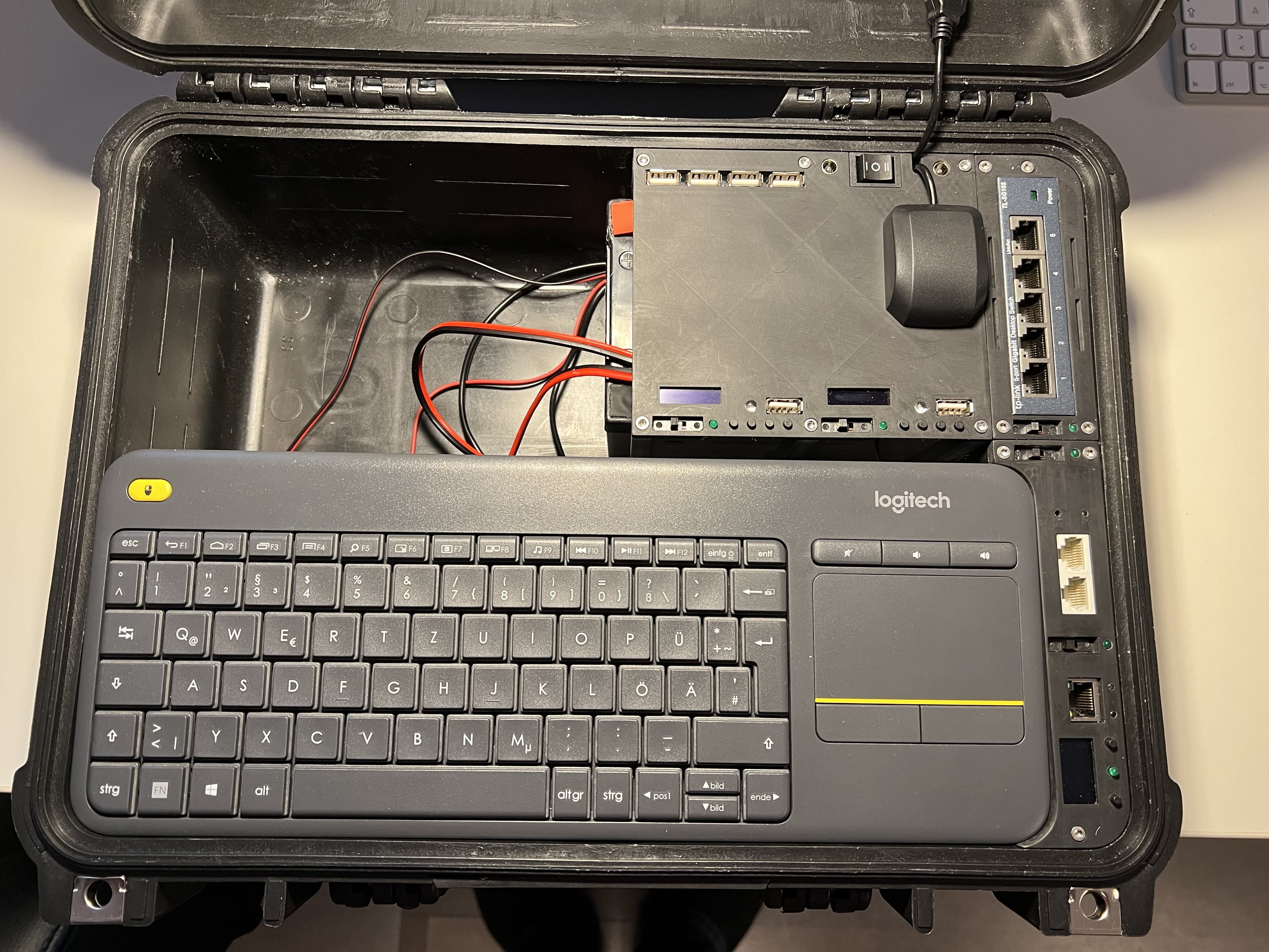
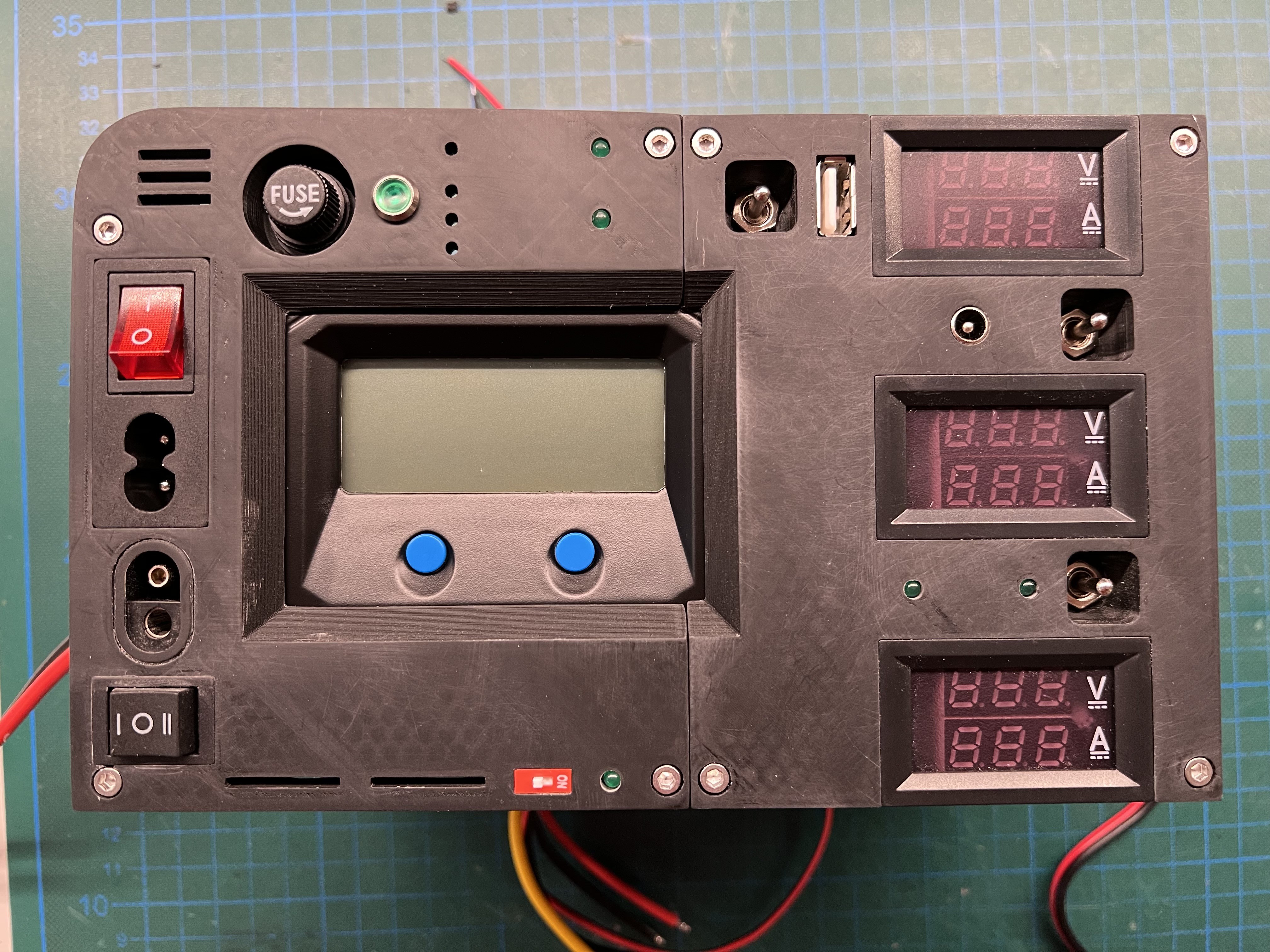
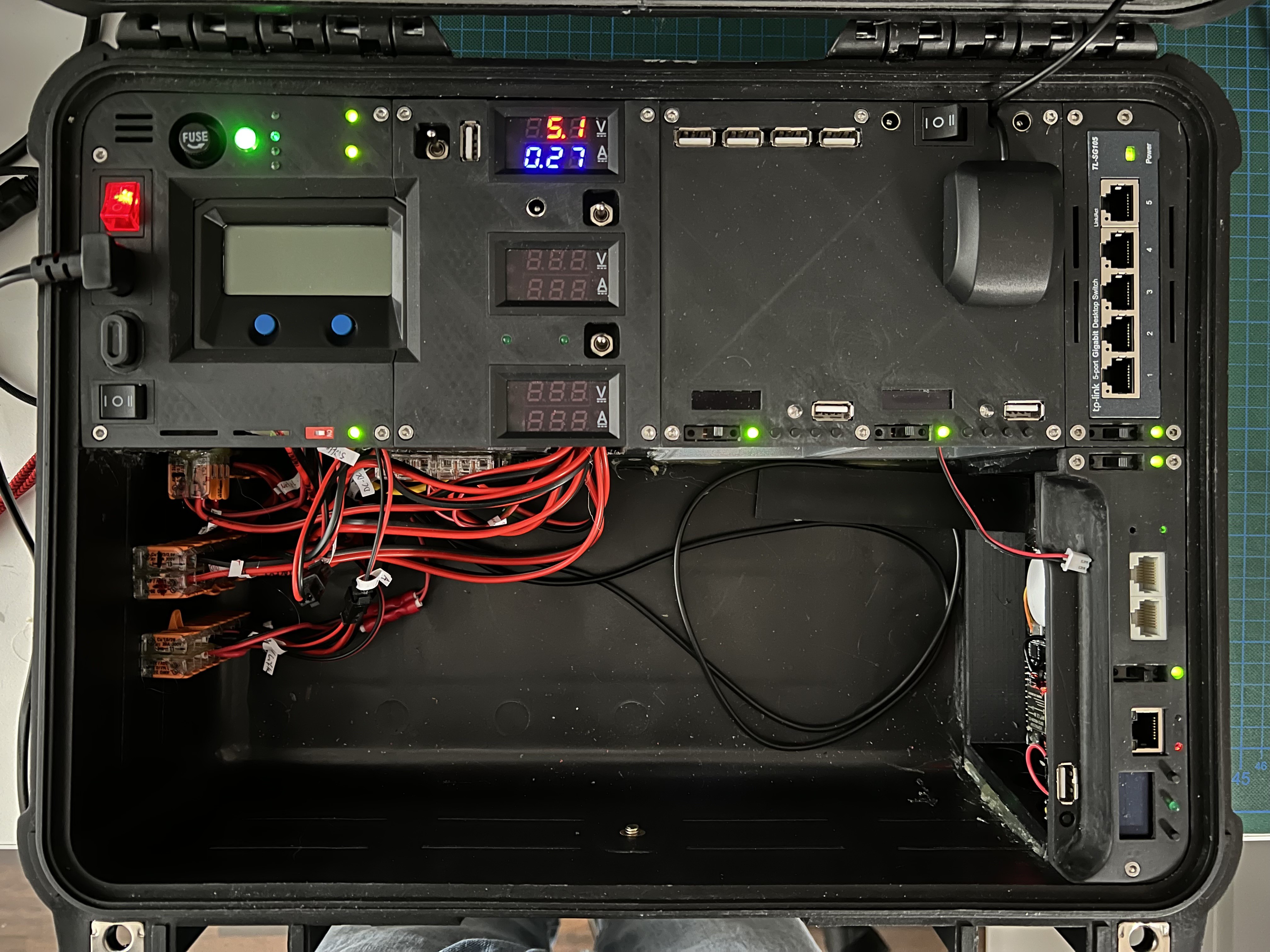
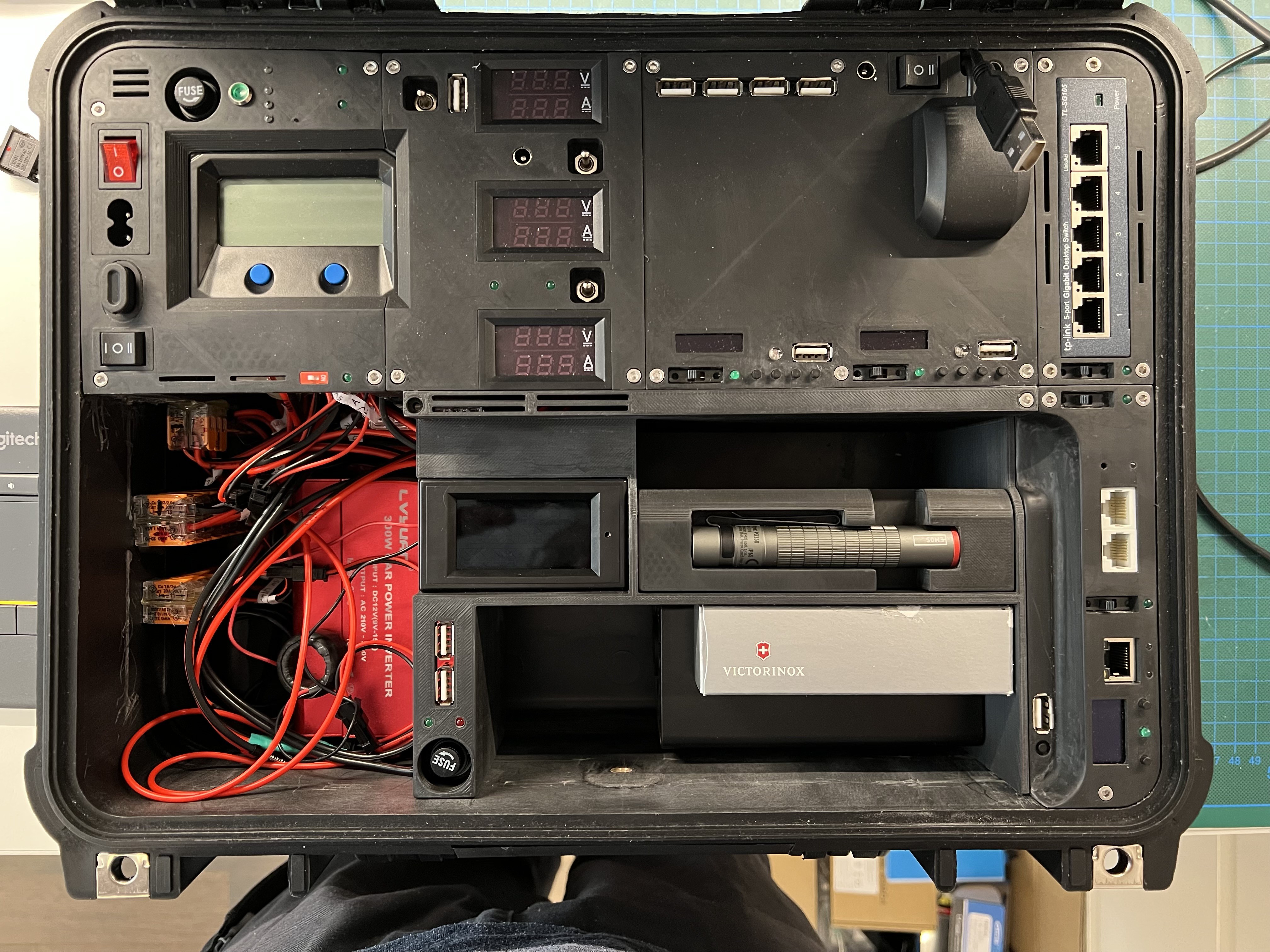
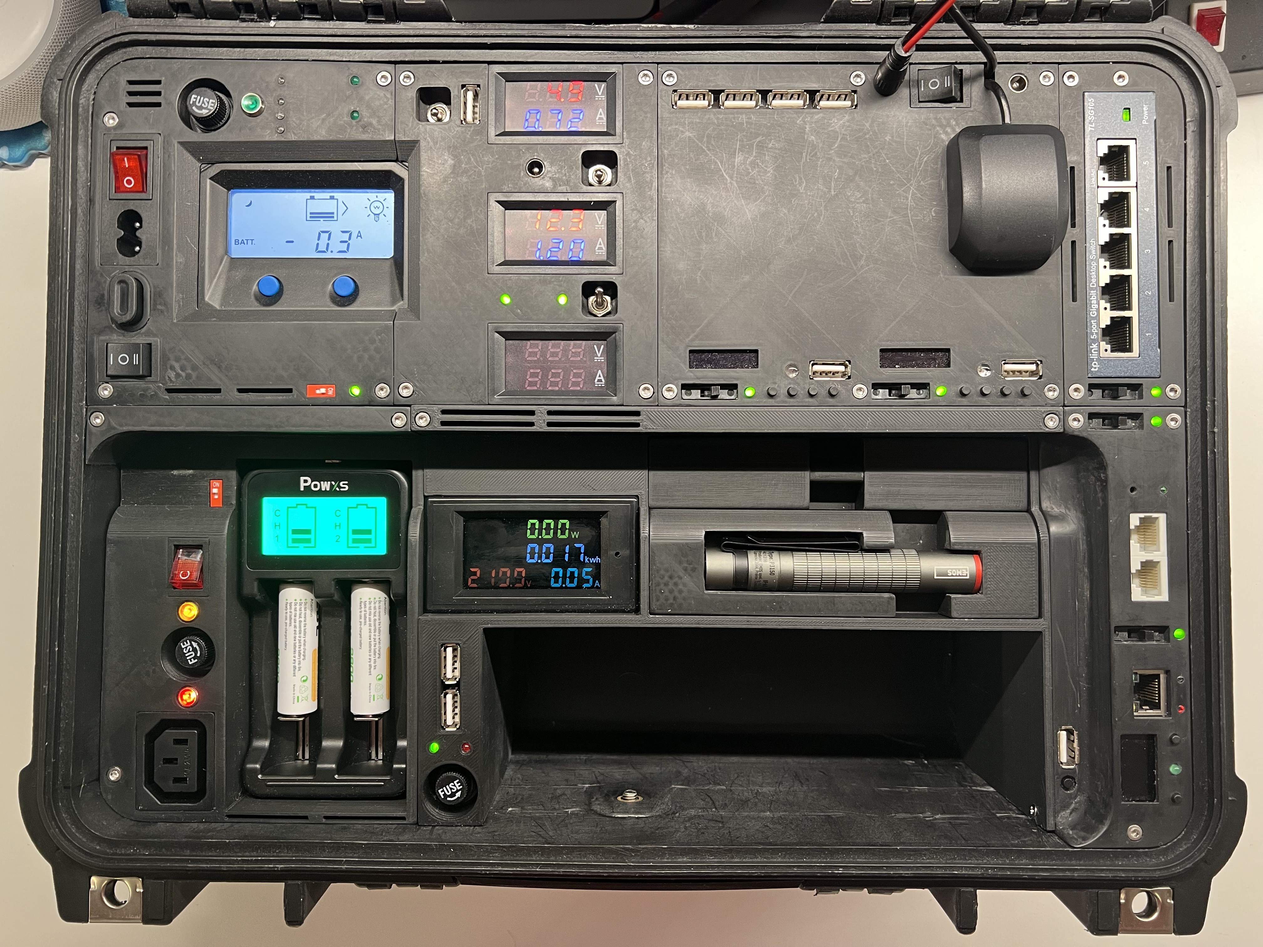
This Cyberdeck shall serve as a multi-functional Disaster Recovery Kit and multi-purpose Cybersecurity and Hacking Field-Lab. As such it is fully packed with features as follows:
The Top Part
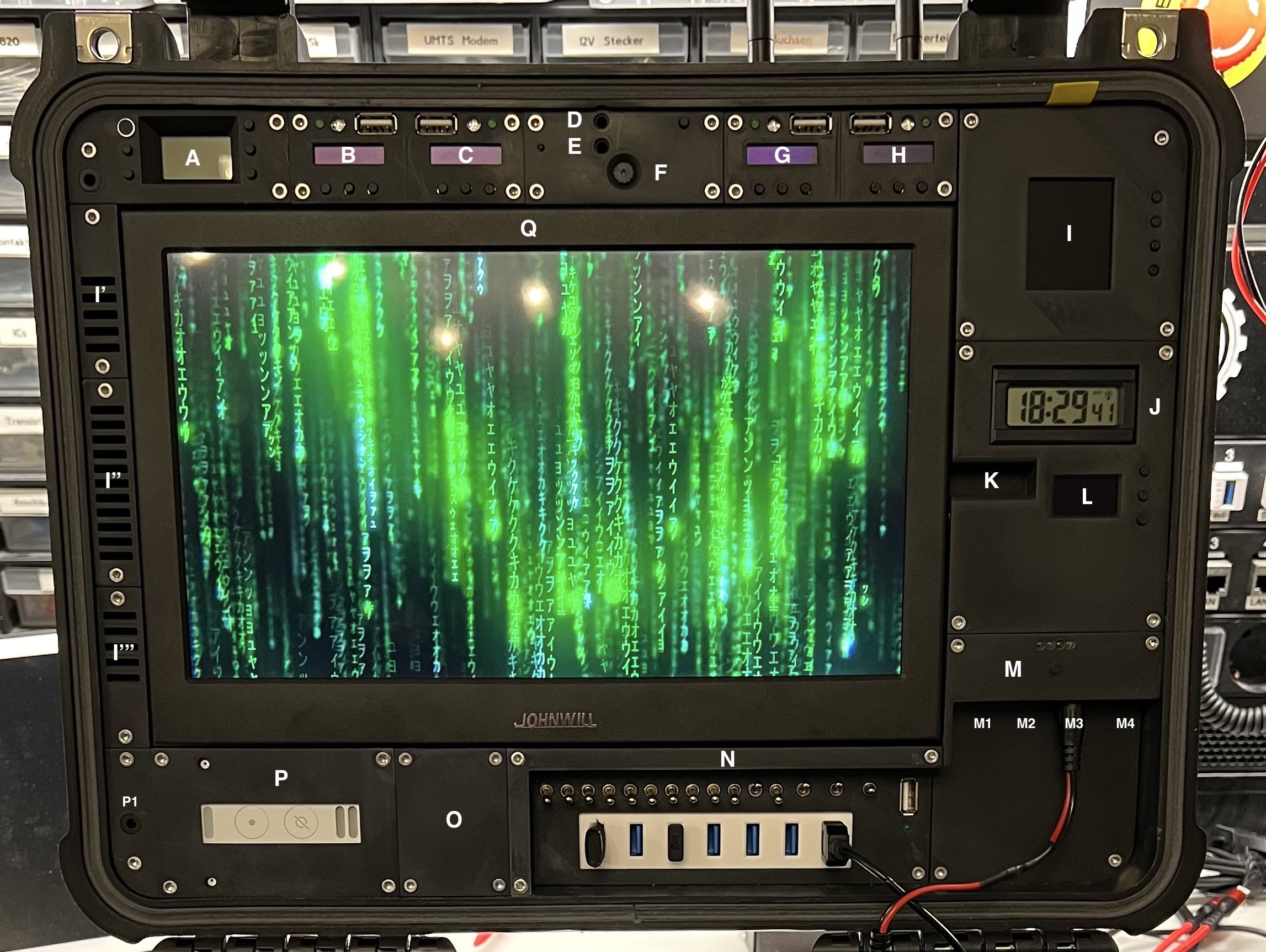
The functional Modules of the Top Part:
- Module A - Radio Transmitter (DONE)
- 88 - 108MHz
- illuminated LCD display
- built-in microphone
- Audio Input (for 3.5mm mini stereo jack plug)
- 4 buttons to control frequency, volume and input source
- external Antenna (on demand mounted)
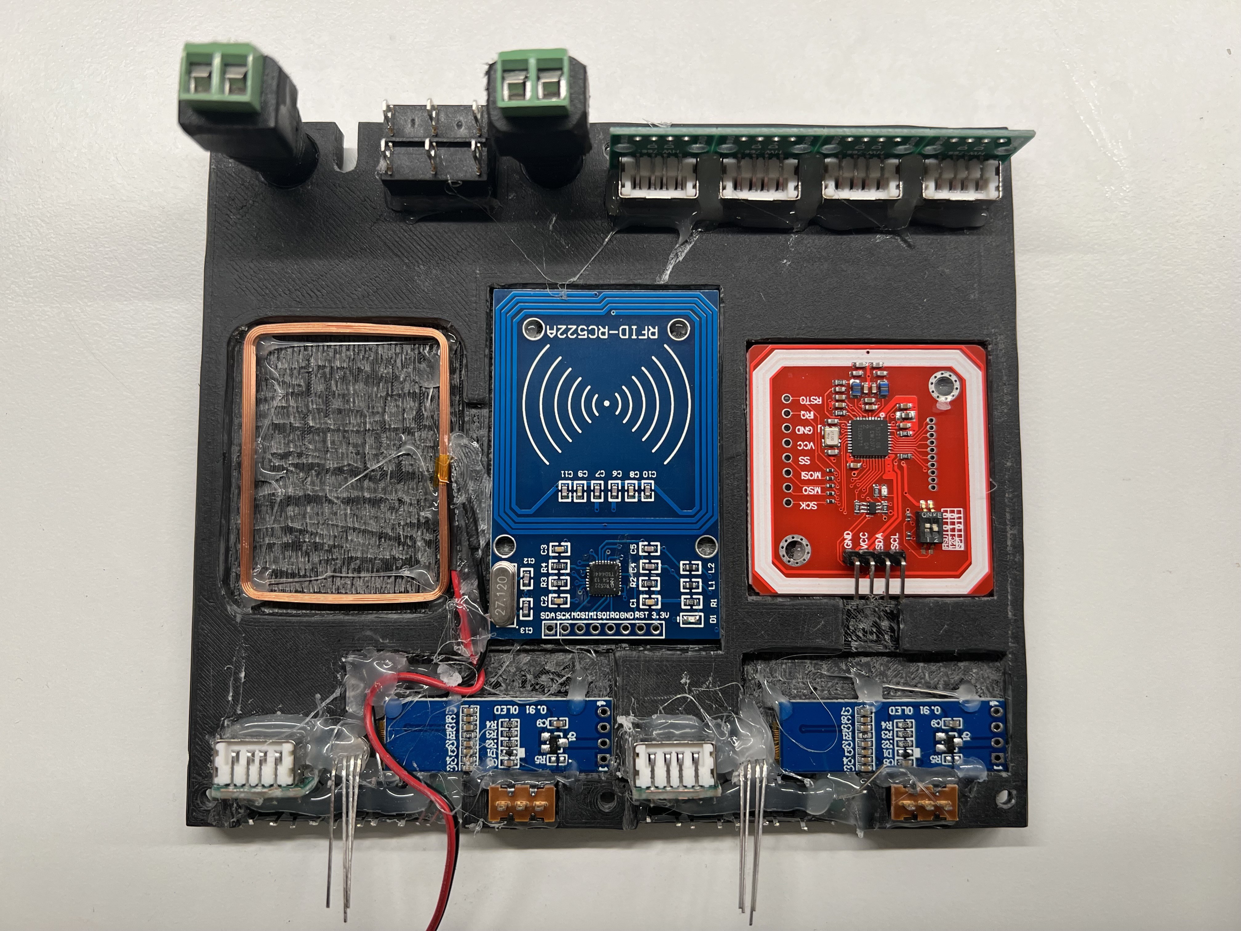
- Module B - 433MHz Analyzer (WiP)
- ESP32
- 433MHz transmitter and receiver
- 0.91'' 128x32 IIC I2C OLED Display Module
- 3 Buttons
- 1 green status LED
- 1 RGB-LED
- USB socket for programming the ESP32 (in the field)
- external Antenna (on demand mounted)
- Module C - 868MHz Analyzer (WiP)
- ESP32
- 868MHz transmitter and receiver
- 0.91'' 128x32 IIC I2C OLED Display Module
- 3 Buttons
- 1 green status LED
- 1 RGB-LED
- USB socket for programming the ESP32 (in the field)
- external Antenna (on demand mounted)
- Module D - Bluetooth Receiver (DONE)
- Audio Output (for 3.5mm mini stereo jack plug)
- Button for pairing
- Module E - Bluetooth Transceiver (DONE)
- Audio Input (for 3.5mm mini stereo jack plug)
- Status Led
- Module F - Webcam (DONE)
- USB 8MP Webcam
- Module G - Bluetooth Analyzer (WiP)
- ESP32
- 0.91'' 12832 IIC I2C OLED Display Modul
- 3 Buttons
- 1 green status LED
- 1 RGB-LED
- USB socket for programming the ESP32 (in the field)
- Module H - LoRaWAN Analyzer (WiP)
- ESP32 LoRaWAN (Heltec)
- 0.91'' 128x32 IIC I2C OLED Display Modul
- 3 Buttons
- 1 green status LED
- 1 RGB-LED
- USB socket for programming the ESP32 (in the field)
- external Antenna (on demand mounted)
- Module I - Weather Station (WiP)
- ESP32
- 1,8"" Serial SPI TFT LCD Modul
- 4 Buttons
- On the lot side under the 10'' Monitor (Module Q) the following sensors are foreseen:
- IKEA Air Dust Sensor
- 3 different Air Quality / Gas Sensors
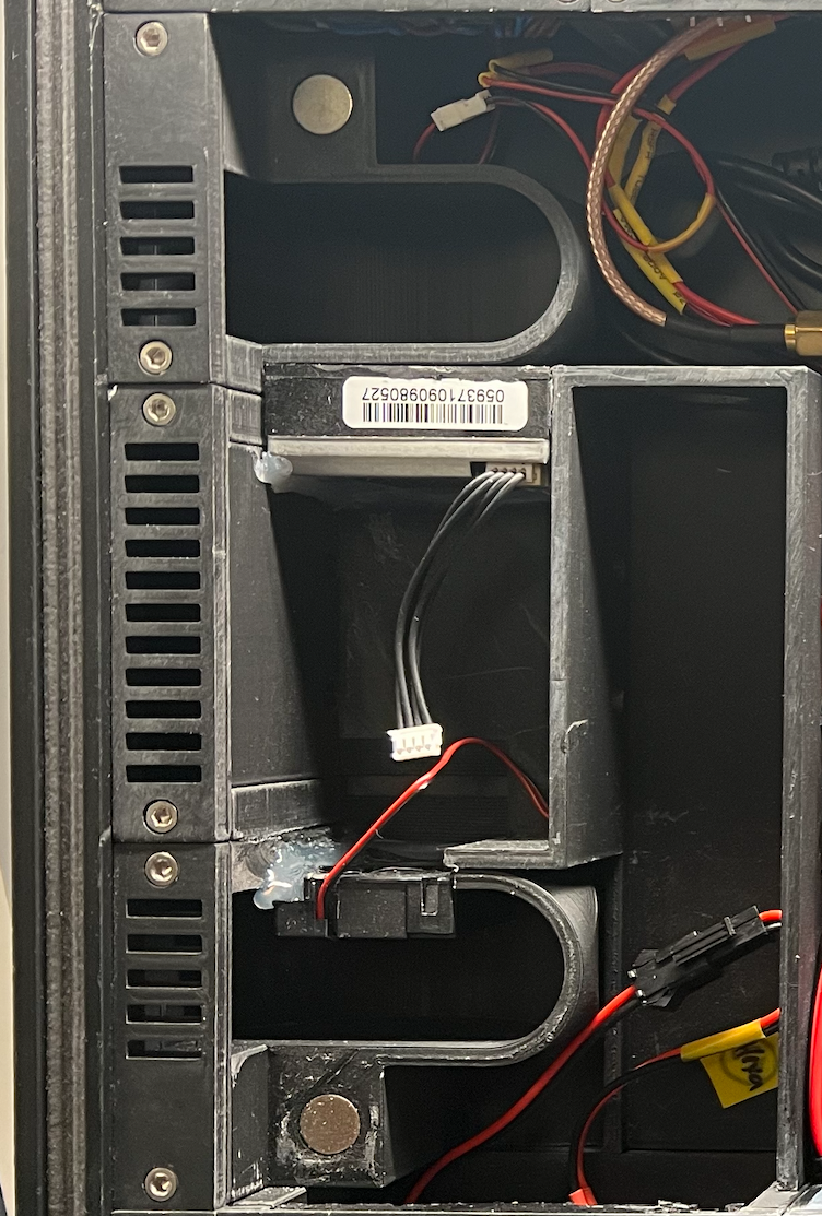
- The fan of the Ikea dust sensor ensures that the air is sucked in via I' (through the dust sensor) and further in an encapsulated duct via the other gas sensors so that the air is then released again via I''', with the help of another small fan.
- I': Air intake (and top stereo speaker)
- I'': Air intake for BMP280
- I''': Air outlet (incl. a small fan)
![]()
- And "One more Thing":
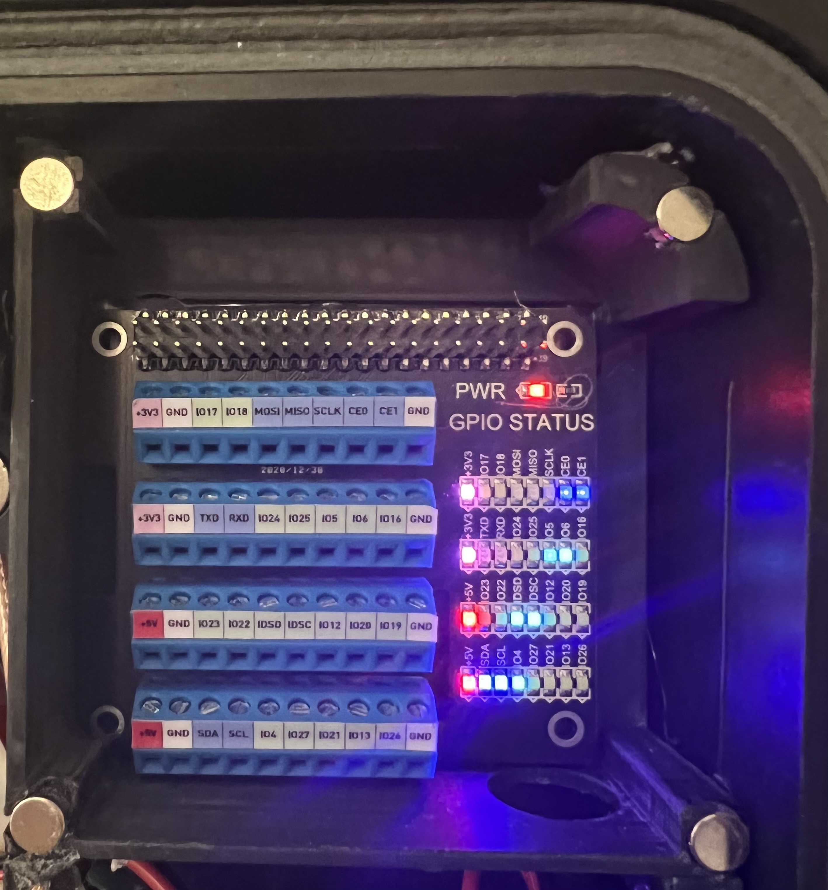
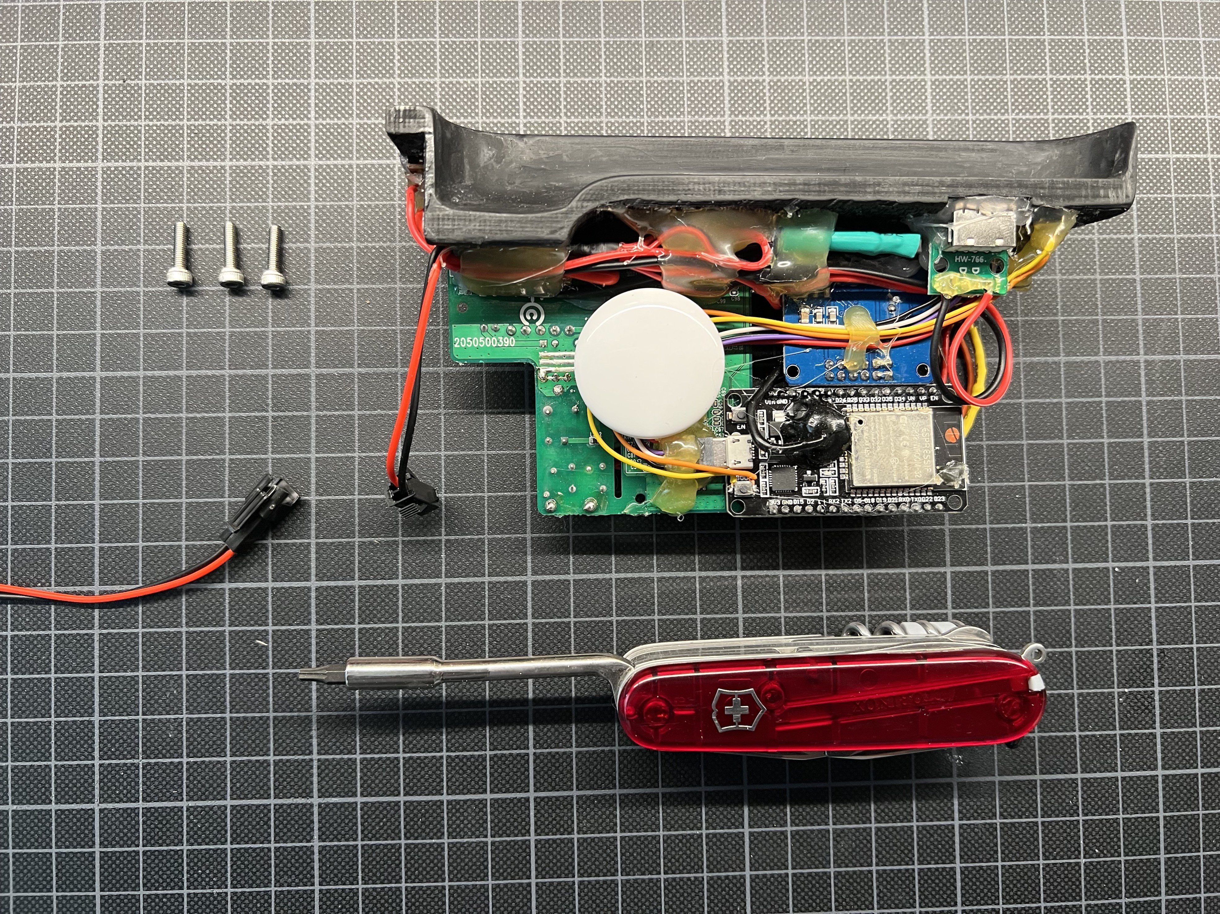
- As a small Hidden Gadget, there is a GPIO Module behind the weather station module that is connected to the Raspberry Pi. To reach the GPIO ports, all you have to do is gently pull the yellow tab and the magnetically held cover will pop off.
![]()
- Module J - Clock (DONE)
- Radio clock module
- Module K - Monitor Audio Output (DONE)
- Audio Output (for 3.5mm mini stereo jack plug)
- Module L - Generic ESP (ToDo)
- ESP32
- 0,96 Zoll OLED Display I2C SSD1306 Chip 128 x 64 Pixel
- 3 buttons
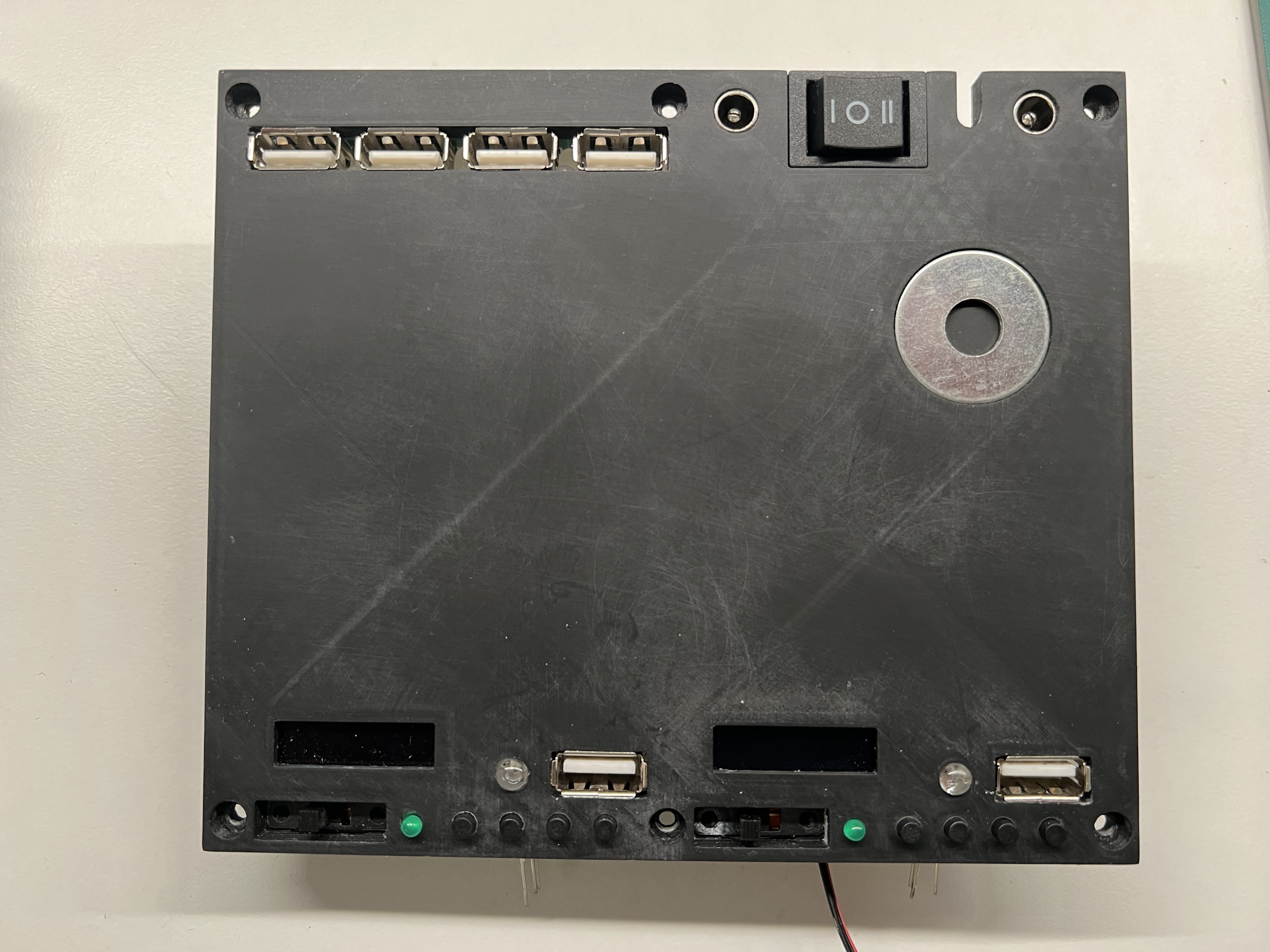
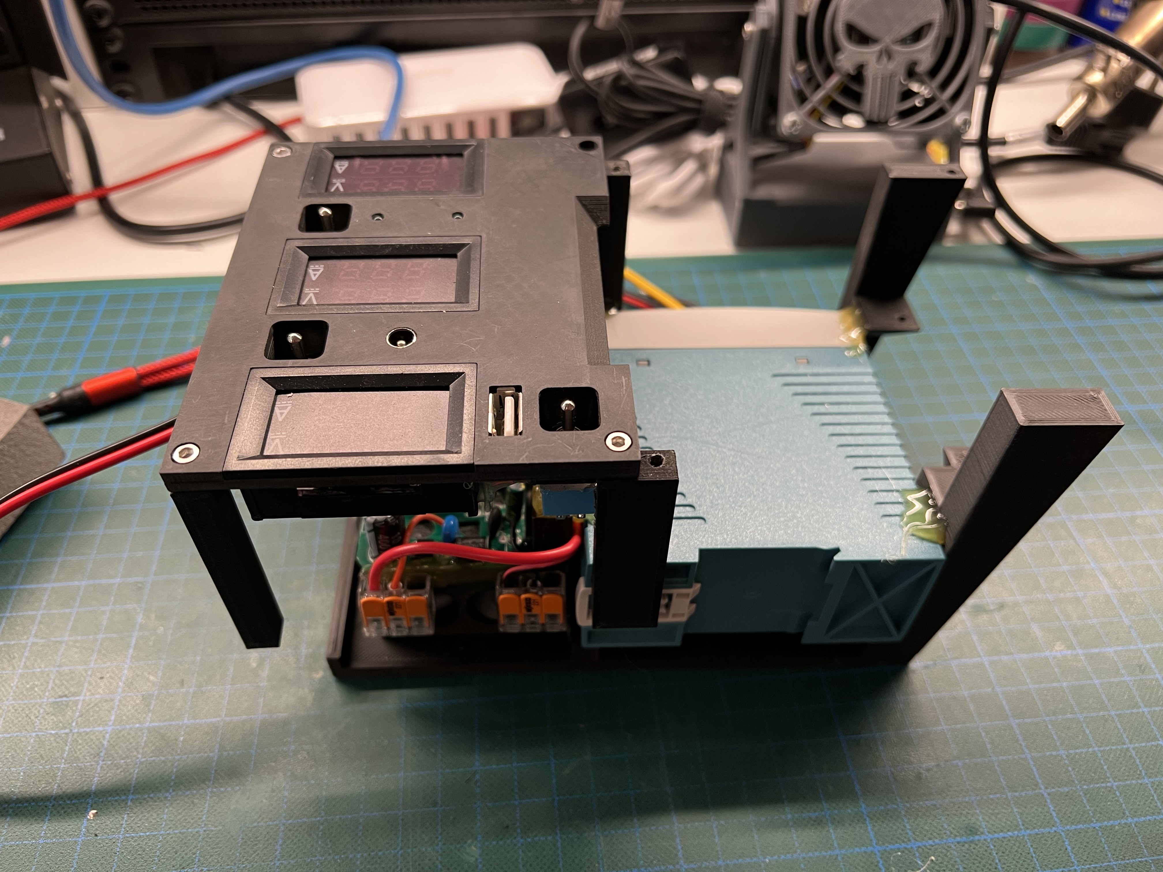
- Module M - USV & Patch Panel (DONE)
- 10.000mAh 5V USV
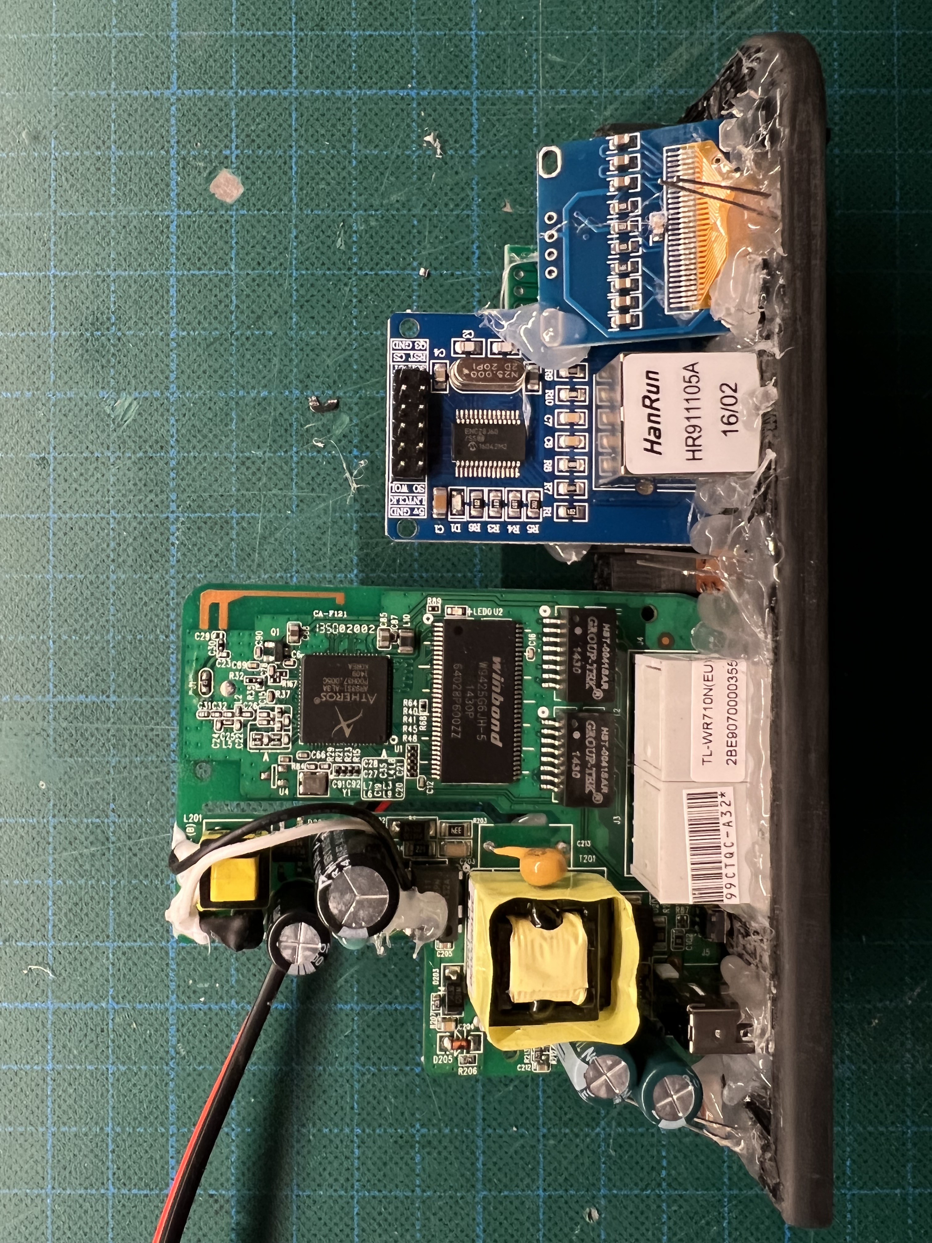
- M1: Ethernet Port of Raspberry Pi4
- M2: Audio Output of Raspberry Pi4 (for 3.5mm mini stereo jack plug)
- M3: 12V Connector (Power Source for Top Case)
- M4: Ethernet Port of LTE/WLAN Router
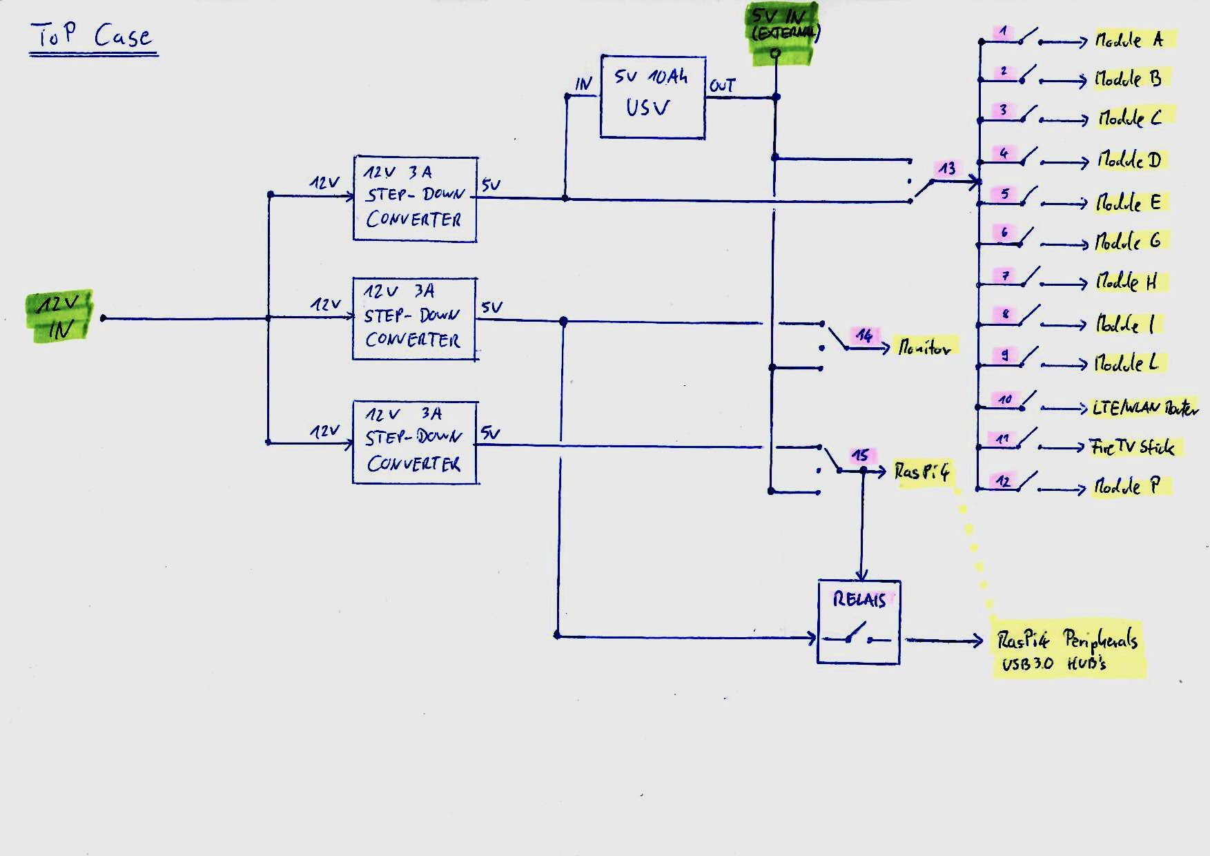
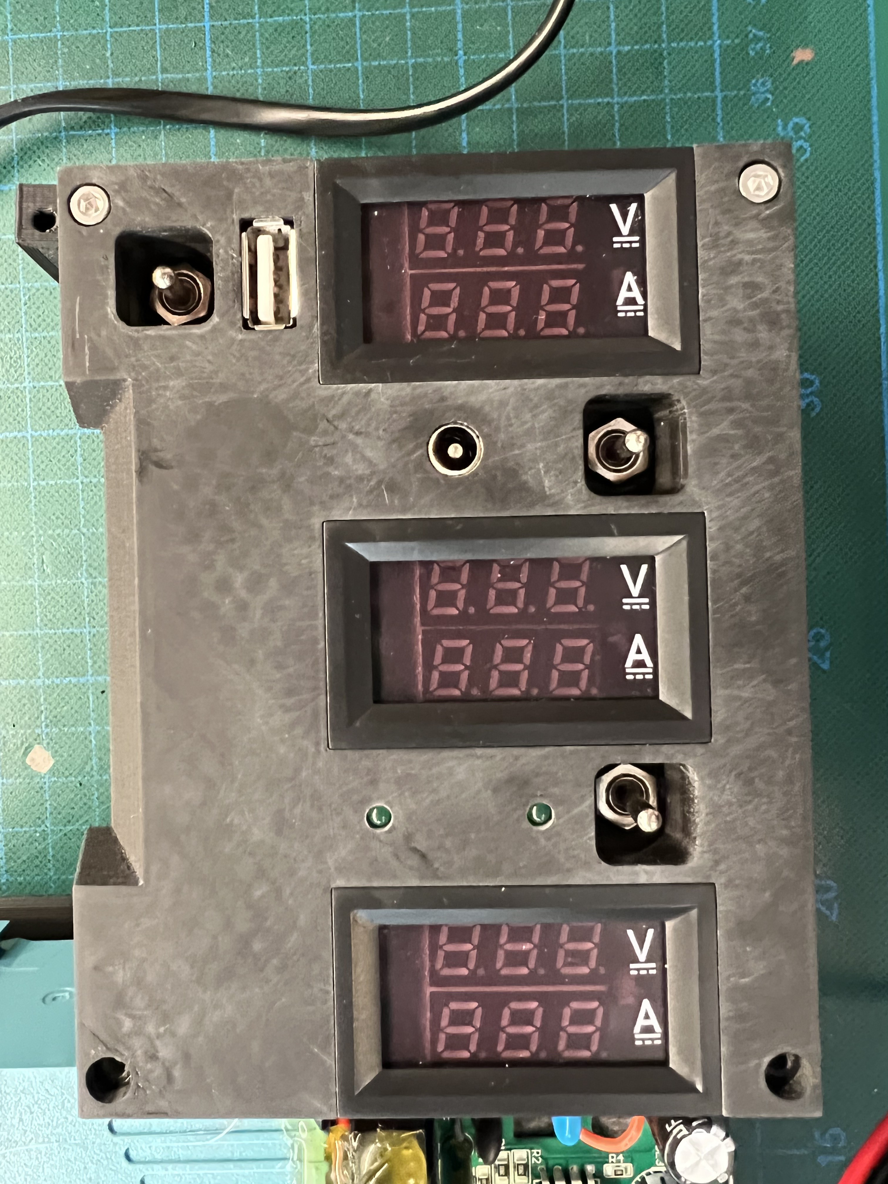
- Module N - Power Switch Panel (DONE)
- 2-Position Switches (ON/OFF - Left to Right)
- 1: Module A
- 2: Module B
- 3: Module C
- 4: Module D
- 5: Module E
- 6: Module G
- 7: Module H
- 8: Module I
- 9: Module L
- 10: LTE/WLAN Router (hidden under Module Q)
- 11: FireTV Stick (hidden under Module Q)
- 12: Module P
- 3-Position Switches (ON/OFF/ON - Left to Right)
- 13: Switch to select the Power Source for Switches 1..12 (USV or 12V-5V Converter C)
- 14: Switch to select the Power Source for the Monitor/Module Q (USV or 12V-5V Converter B)
- 15: Switch to select the Power Source for the RasPi4 (USV or 12V-5V Converter A)
- USB Socket (for external Power Sources, like an USB Power Bank)
- Status LED (USV / External Power)
- 2-Position Switches (ON/OFF - Left to Right)
- Module O - UNUSED
- Placeholder for another module in the future.
- Module P - Alexa (DONE)
- Amazon Echo Flex (brutally stripped down to the bare minimum)
- P1: Audio Output of Raspberry Pi4 (for 3.5mm mini stereo jack plug)
- Module Q - 10'' Monitor (DONE)
- HDMI input #1 for the RasPi4 (auto select)
- HDMI input #2 for the FireTV Stick (auto select)
- HIDDEN (behind Module Q)
- Raspberry Pi 4
- 5-Port USB 3.0 HUB
- FireTV Stick...
 Lord Of All Things



 f4drj
f4drj
 Denis
Denis
 Cole B
 Michel Kuenemann
I really like this build and really interested in how you created the GPIO status indicator panel? I've been trying to work out how to build something like this for a raspberry pi 4.
It's an inspirational project you've created and great notes. Thank you for sharing.