Close
0%
0%

DIY pocket thermal imager

Very easy to repeat and inexpensive pocket-sized DIY thermal imager

Public Chat
Similar projects worth following
The thermal imager is based on MLX90640 sensor from Melexis. It does all the hard work, although thermal post-processing is also necessary.

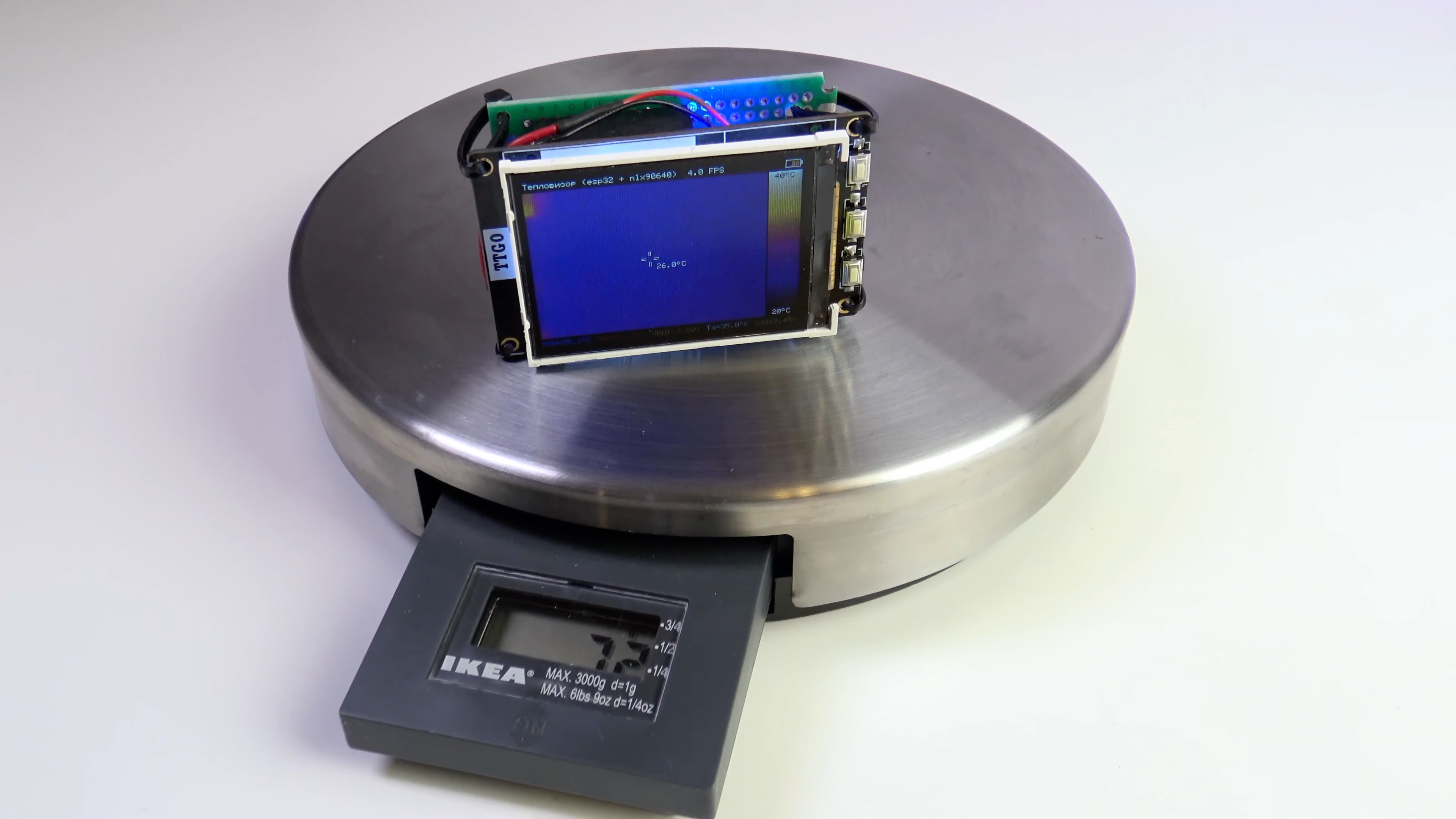
Operating time on 1 battery charge - 8 hours 40 minutes.

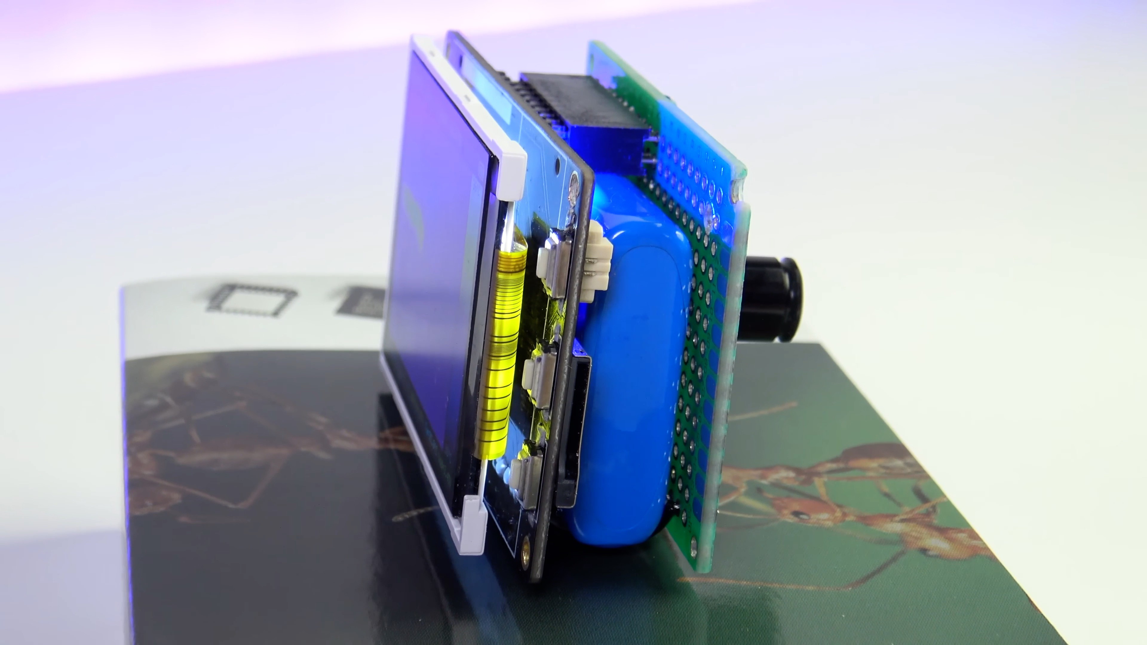
Thermal imager weight (without case) - 72 grams 

Let's take a closer look at the details of the project…
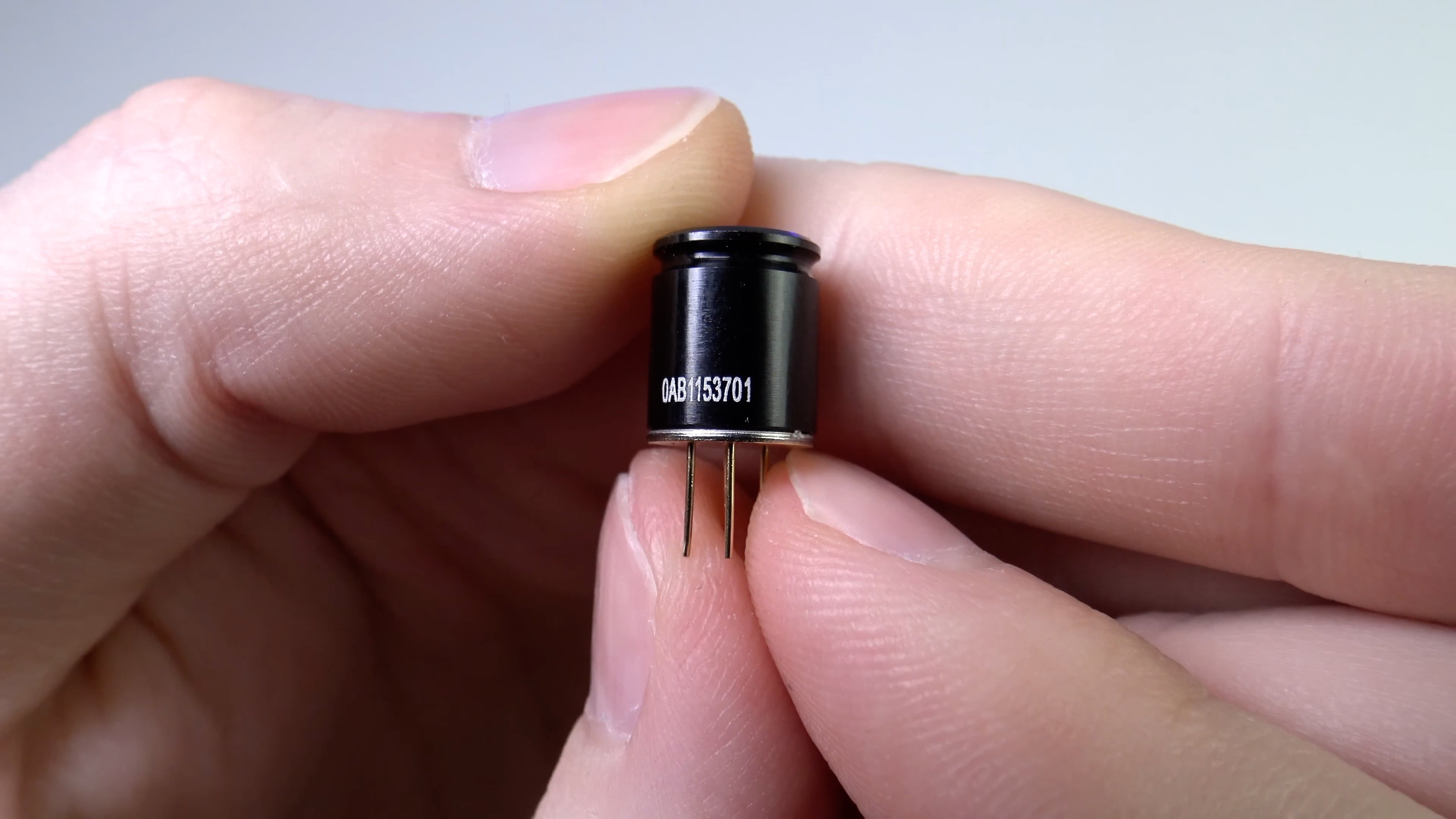
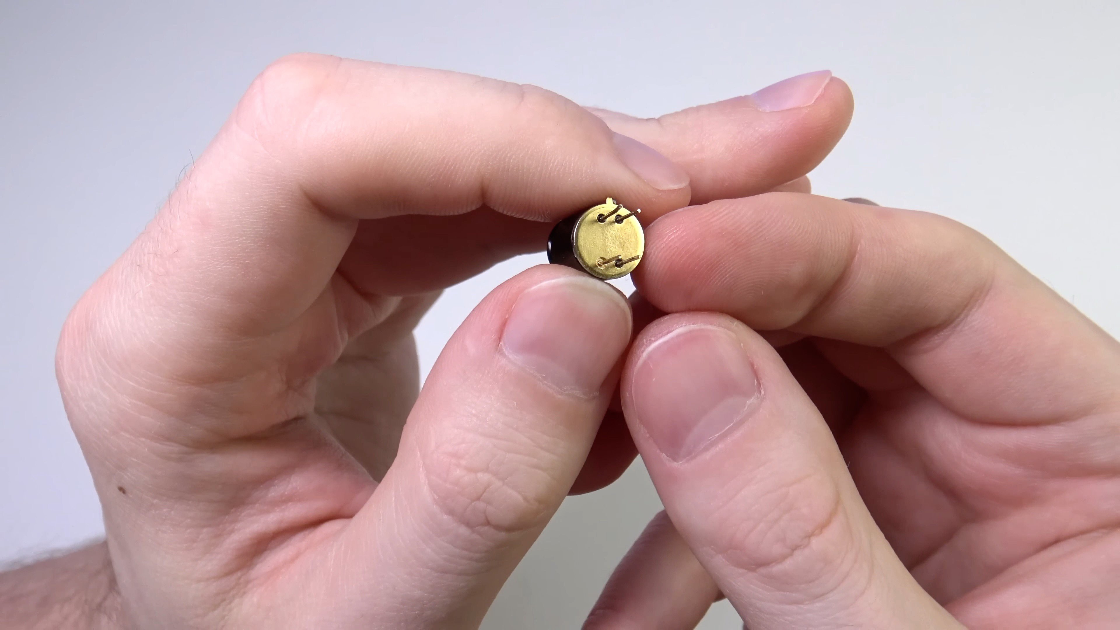
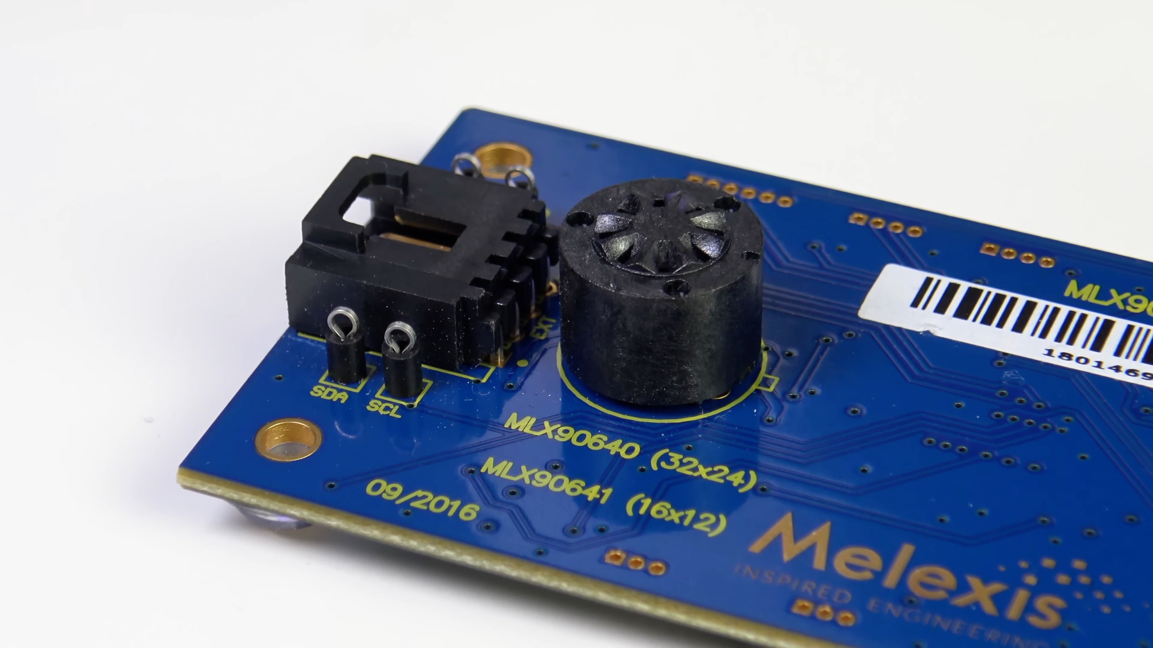
MLX90640 sensor

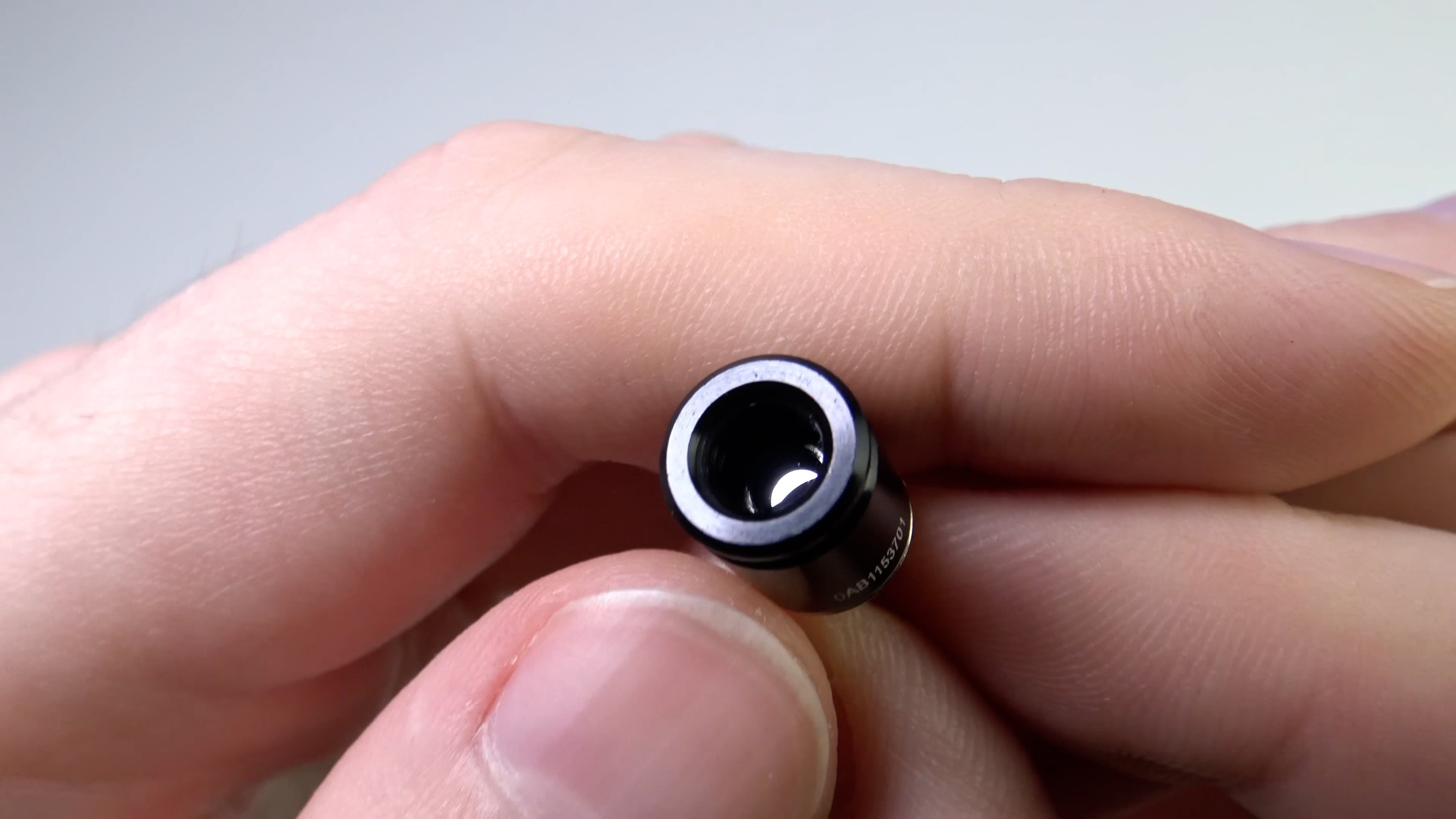
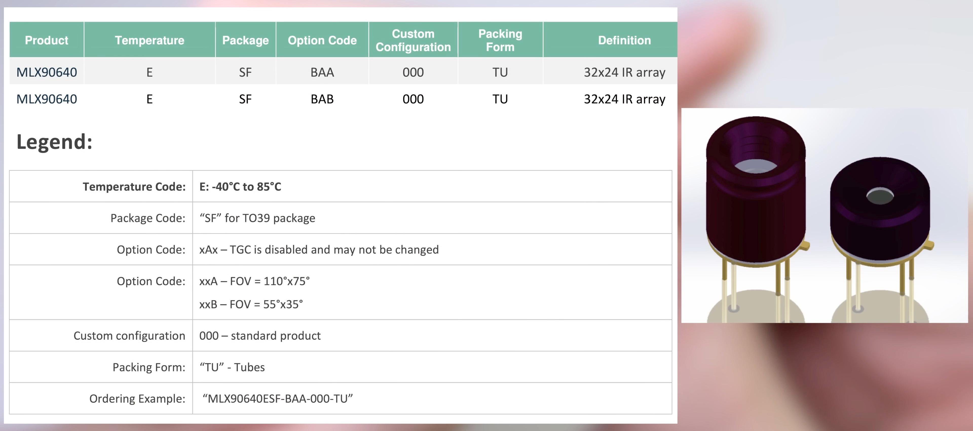
There are 2 versions of the sensor:

With the letter A in the name has FOV 110 / 75

With the letter B in the name it has FOV 55 / 35 - I have one

Inside the sensor is a 32x24 matrix of elements sensitive to IR radiation. The manufacturer allows up to 4 defective pixels. They are stored in EEPROM and are considered to be interpolation from neighboring pixels. 

Inside the sensor there are 768 IR receivers (!!!) + VDD meter + built-in chip thermometer (it estimates the temperature of the sensor case). 

The sensor is factory calibrated. Calibration coefficients are stored internally in the sensor in EEPROM. 

Temperature range: -40…+300

Operating temperature range: -40 ... +85

The sensor is powered by 3.3 V (up to 3.6 V). Withstands 5V supply for a short time. 

Average current consumption 20 mA. 

The sensor has 4 pins. 2 of them for power and 2 more for the i2c interface. 

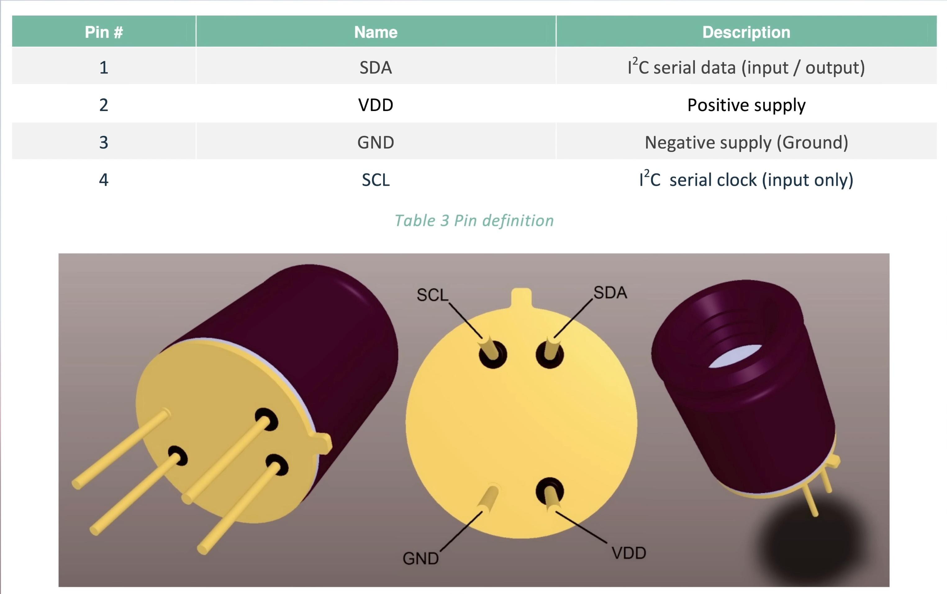
The i2c pins are 5V tolerant. The i2c frequency is up to 1MHz. The i2c address can be changed by software, the default is 0x33.

Software from Melexis

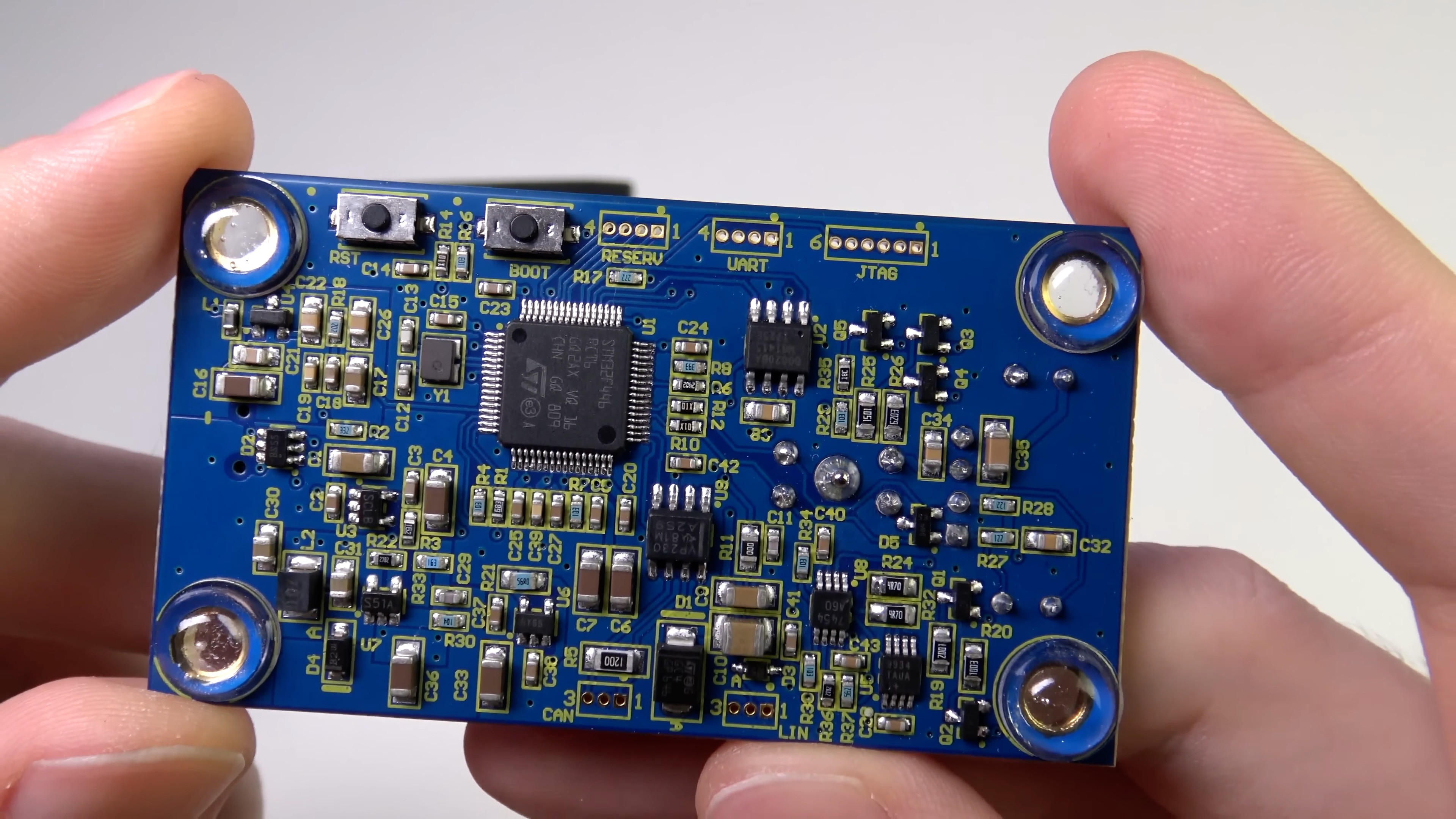
In addition to the sensor, I have an evaluation board from melexis (EVB90640-41).

The board allows you to connect the sensor to a computer.

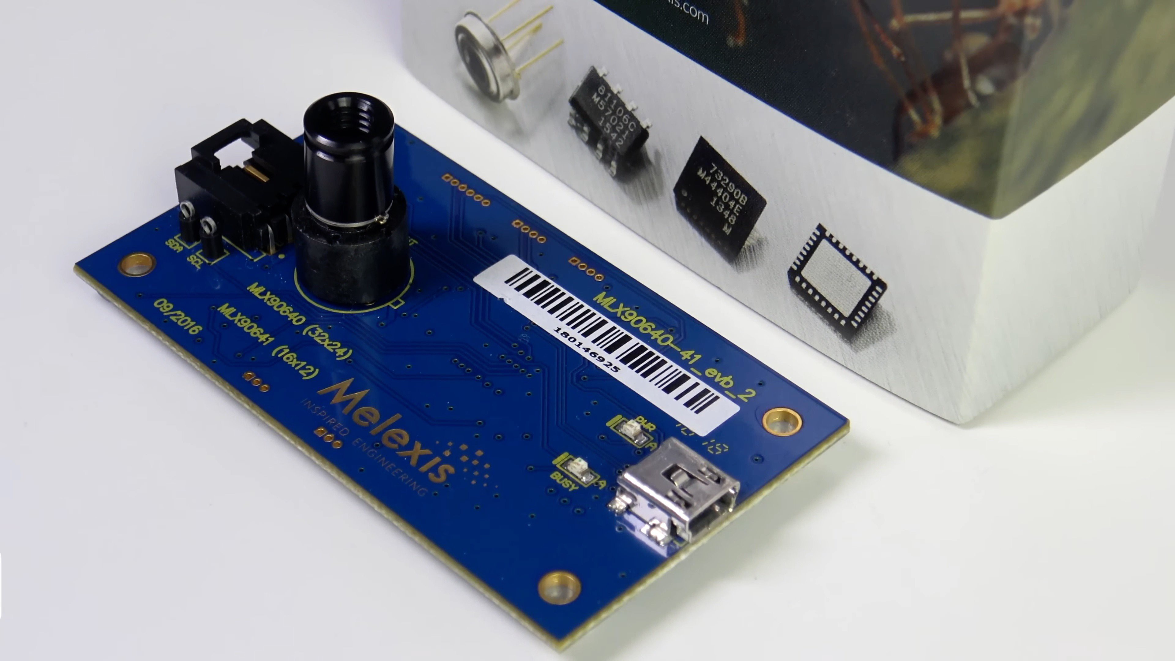
The board has a socket where you need to insert the sensor, and a mini-USB port for connecting to a computer.

The evaluation board is based on the STM32F446 microcontroller.

The board has CAN and LIN interfaces. The purpose of these interfaces is unknown to me. Most likely Melexis implemented them for one of their customers.

VP230 - CAN transceiver

80020BA - LIN transceiver

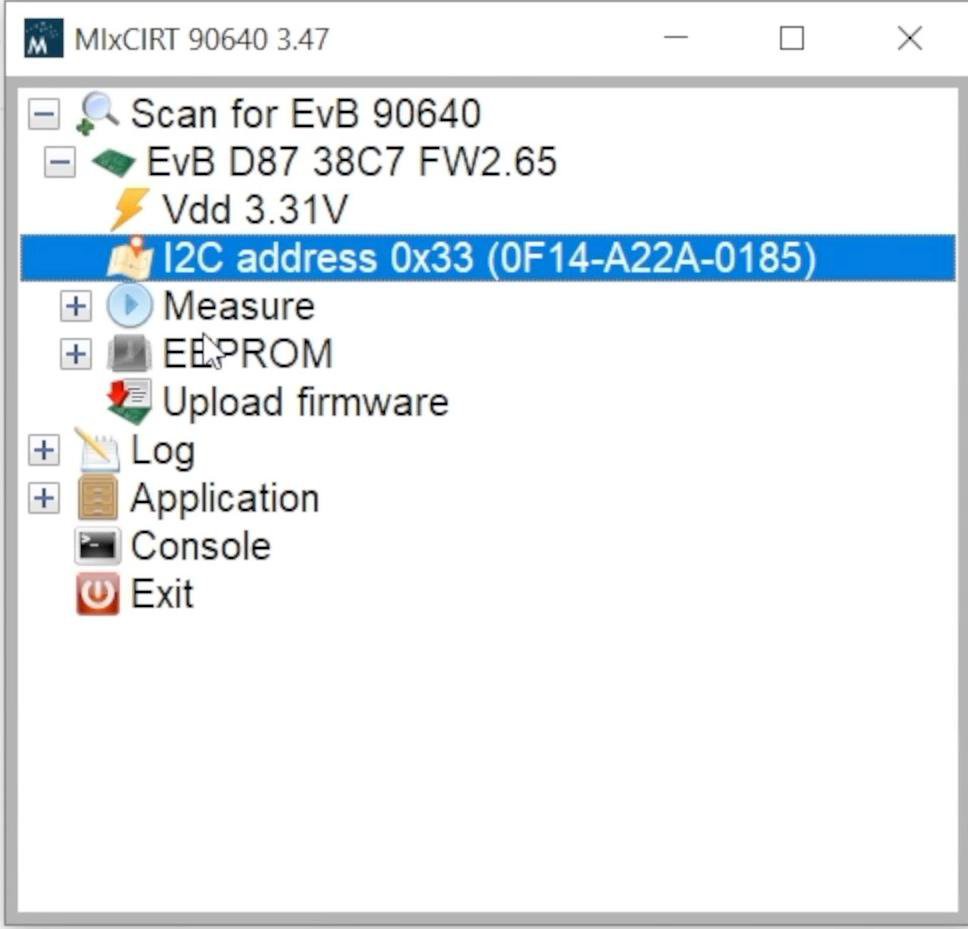
In MlxCIRT 90640 software, you can view general information about the sensor, start data acquisition and configure parameters in EEPROM.

The frame rate is selectable from 0.5 Hz to 64 Hz. 

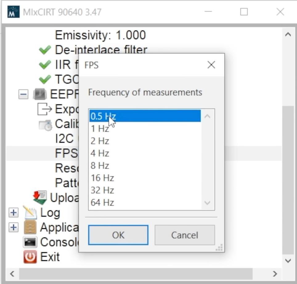
This is the frequency of reading half a frame from the matrix (the matrix is scanned in 2 stages using a checkerboard or interlaced pattern). 

The matrix scan template can also be selected in MlxCIRT 90640. The manufacturer recommends the chess template because the factory calibration is done for it.

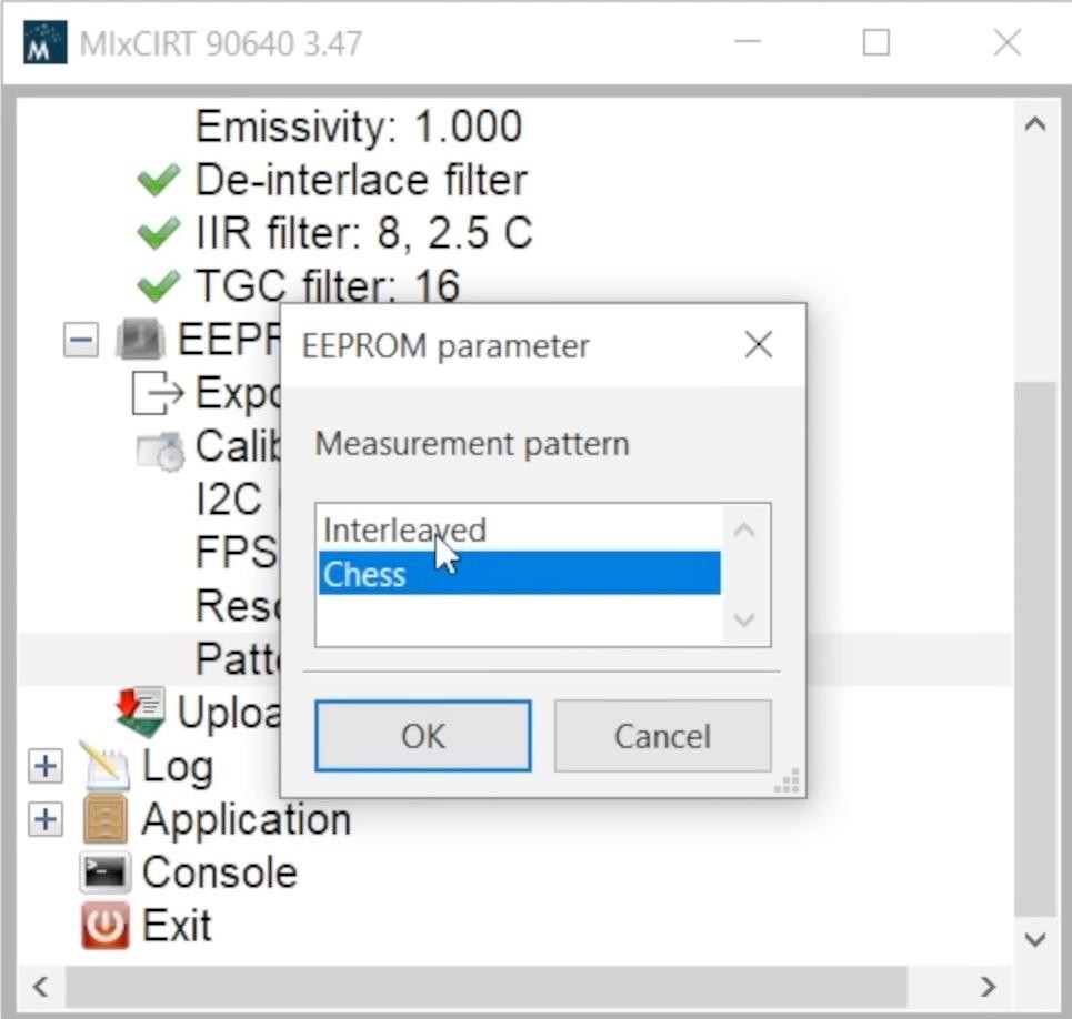
You can update the firmware of the demo board in MlxCIRT 90640.

Reading thermograms is possible in a CSV file for further analysis.

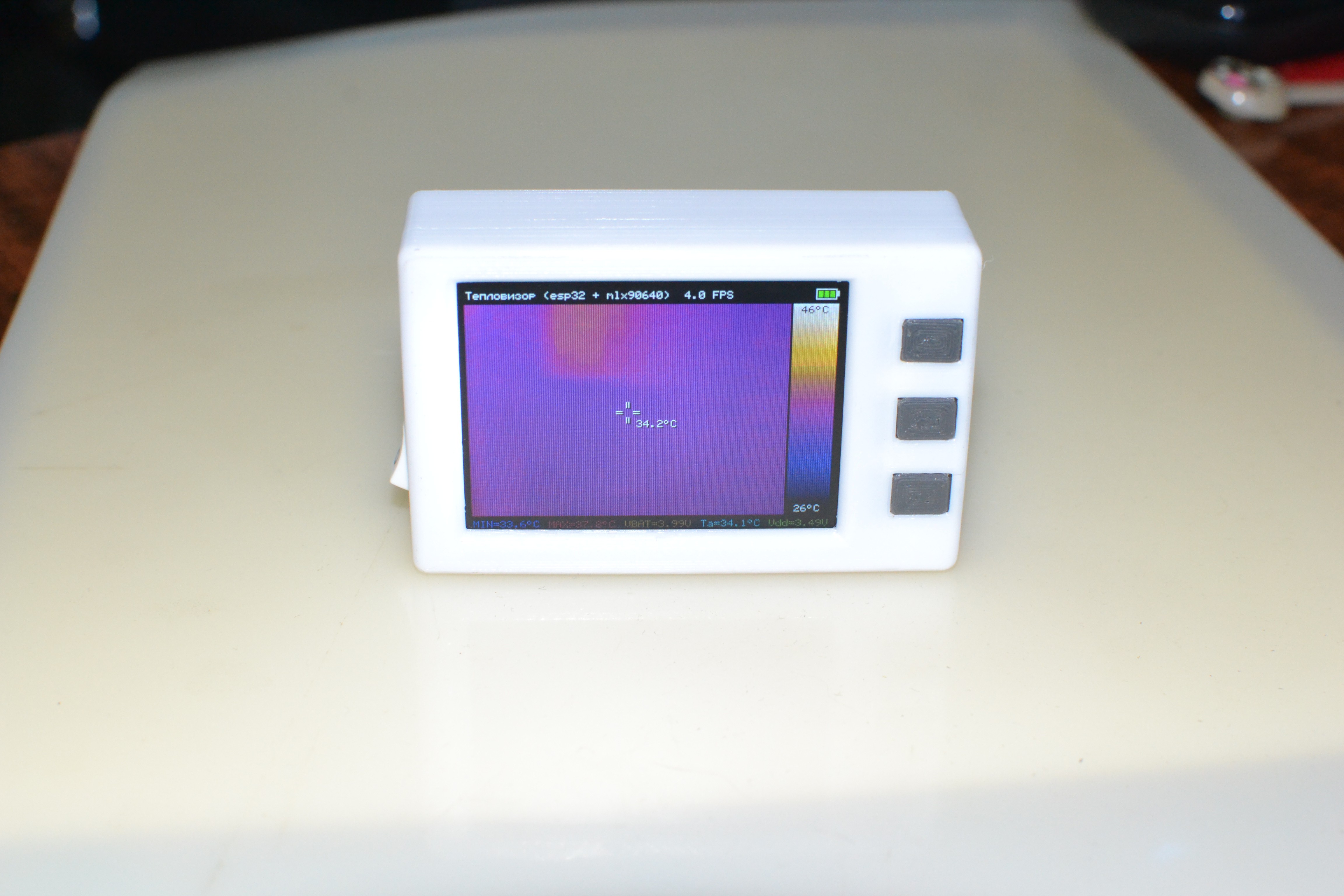
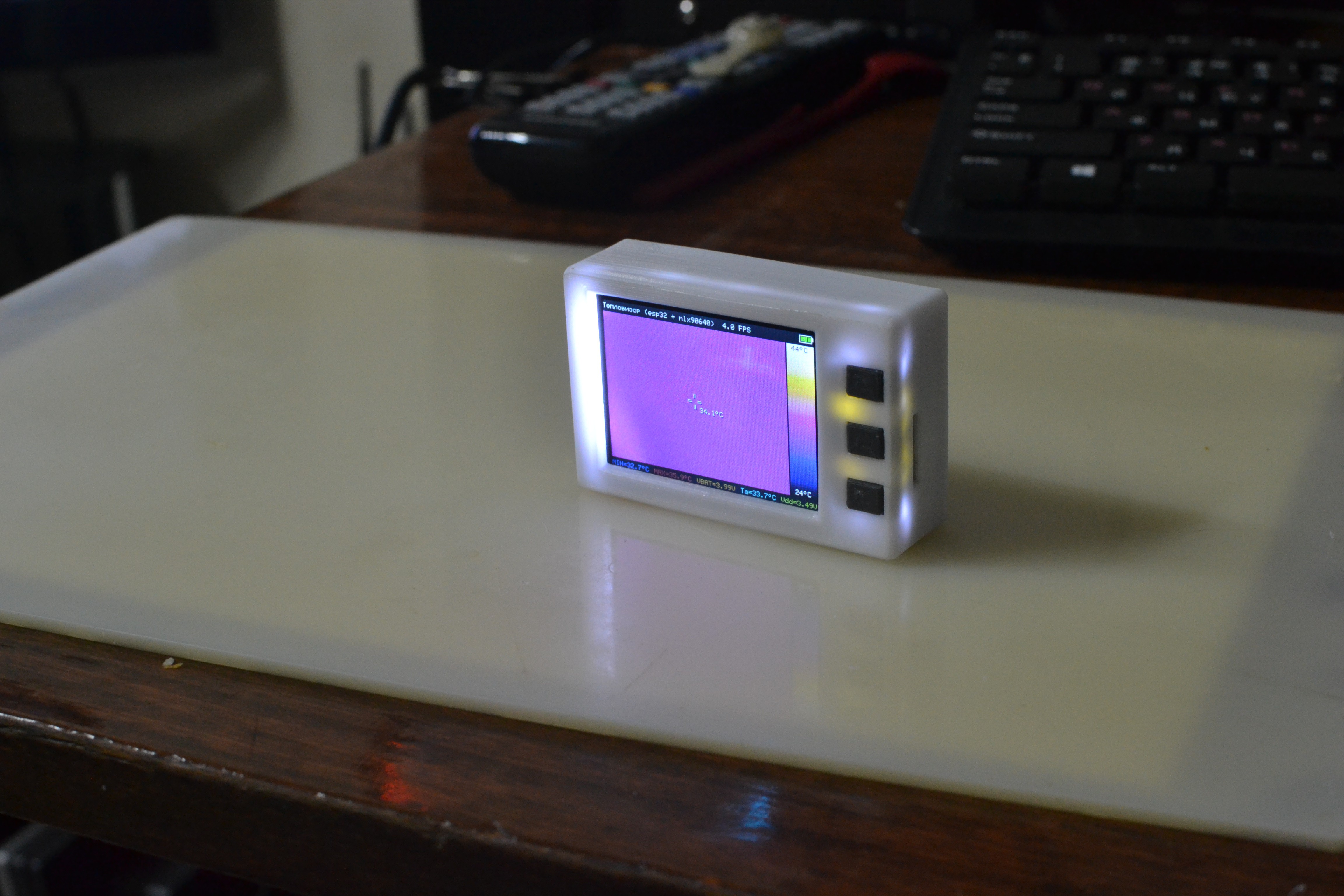
Let's start reading thermograms.

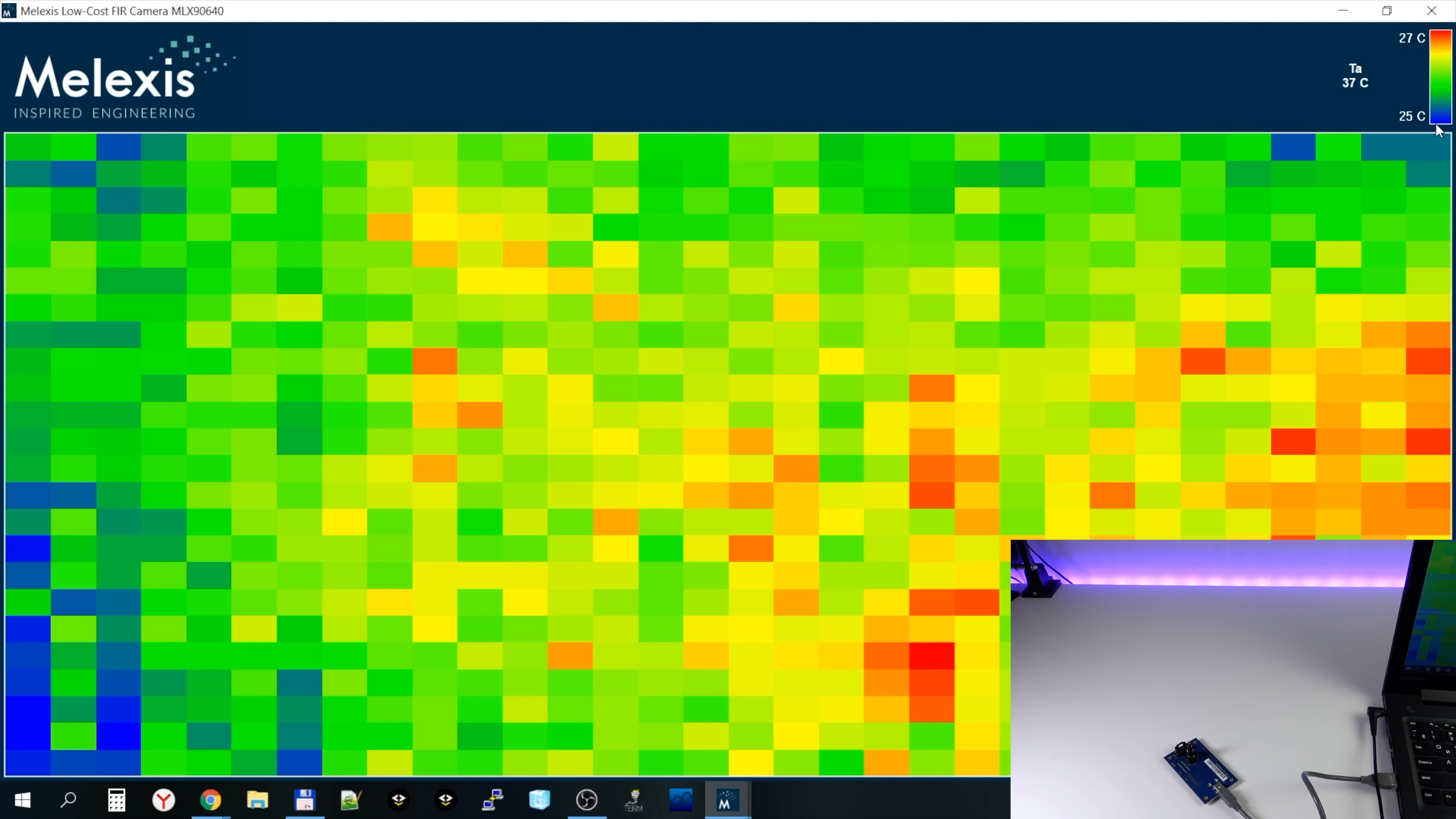
Now the sensor is directed to the ceiling. There are no hot and cold objects on it and you see a rather noisy image. This is because the software has automatically chosen a very narrow temperature range for the color scale - only 2 degrees.

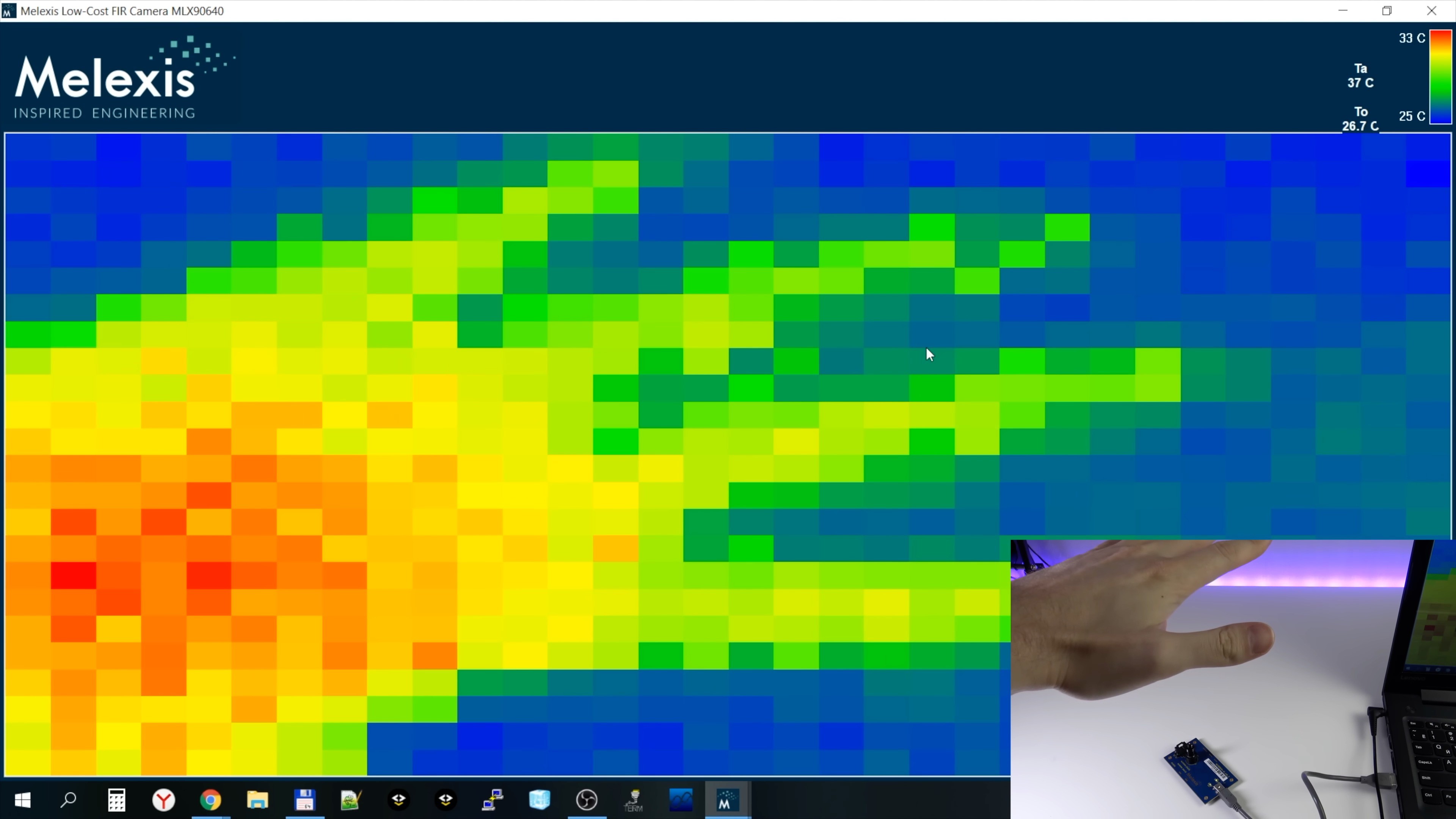
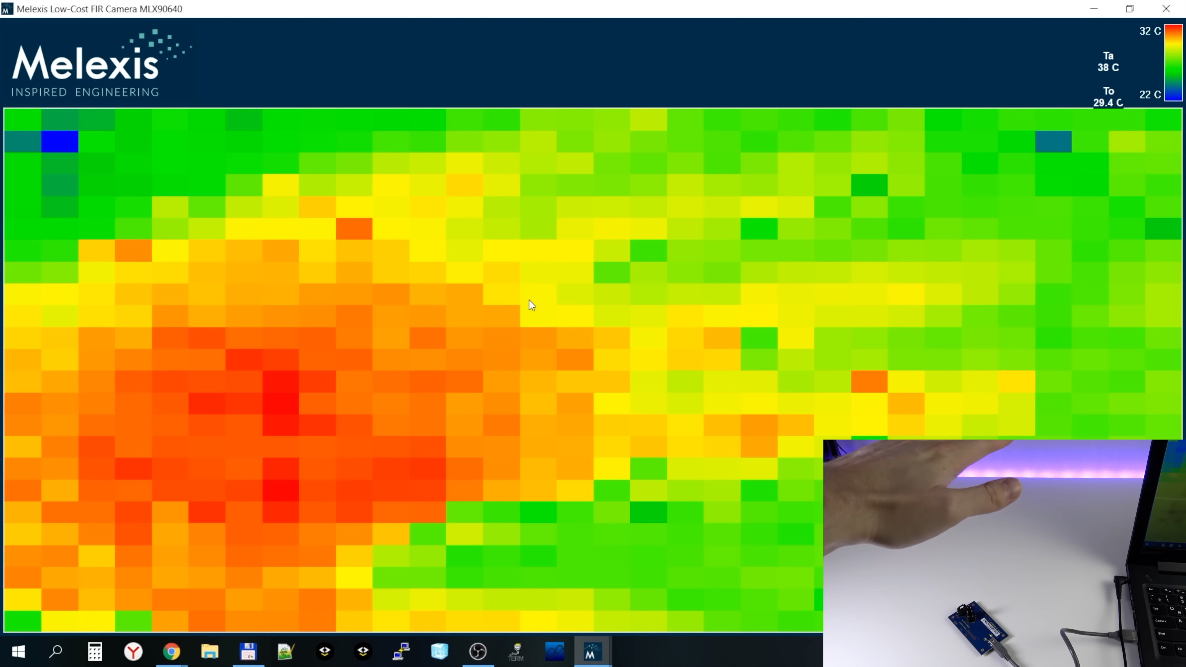
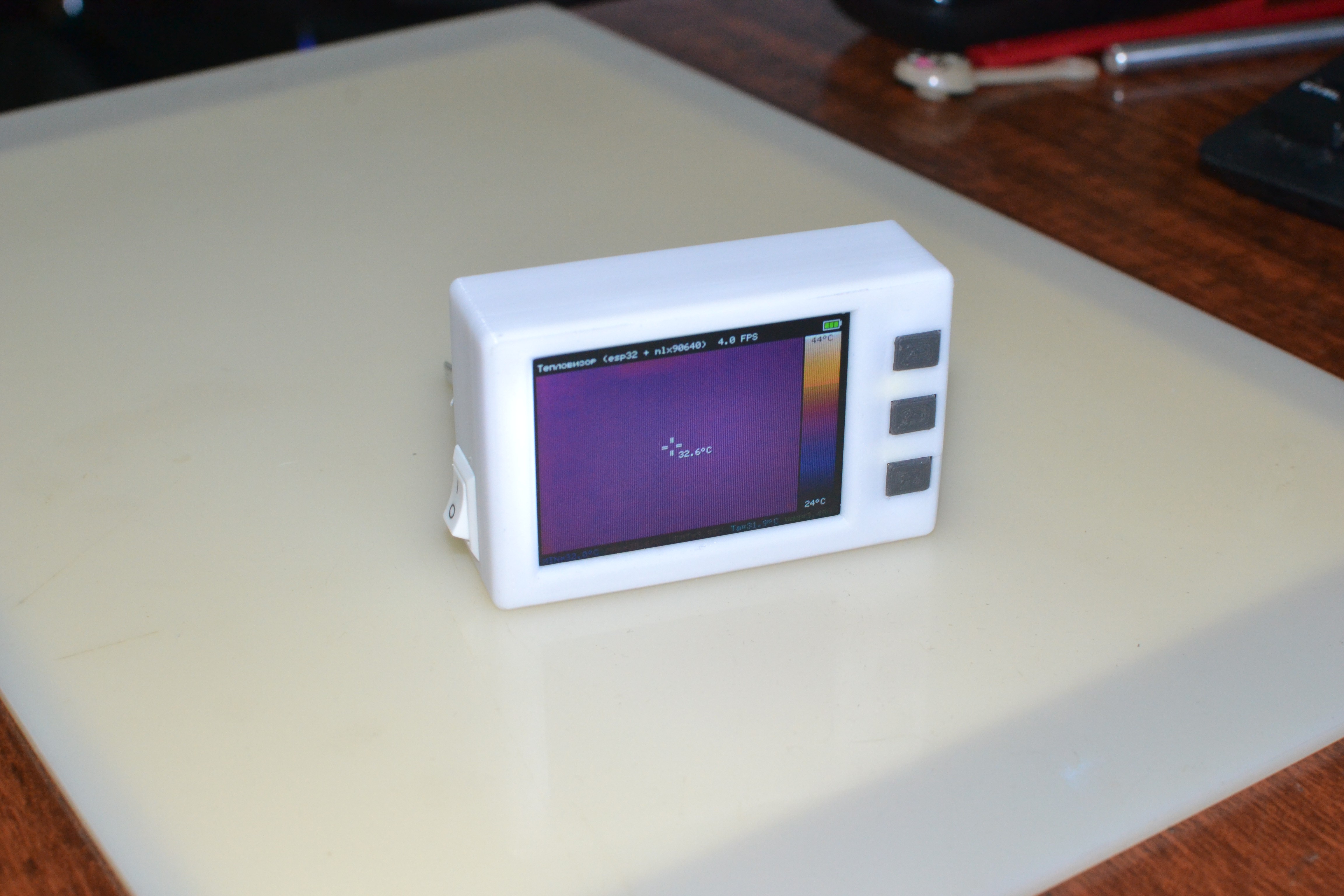
Now I brought my hand into the field of view of the sensor and this is what the thermogram looks like now:

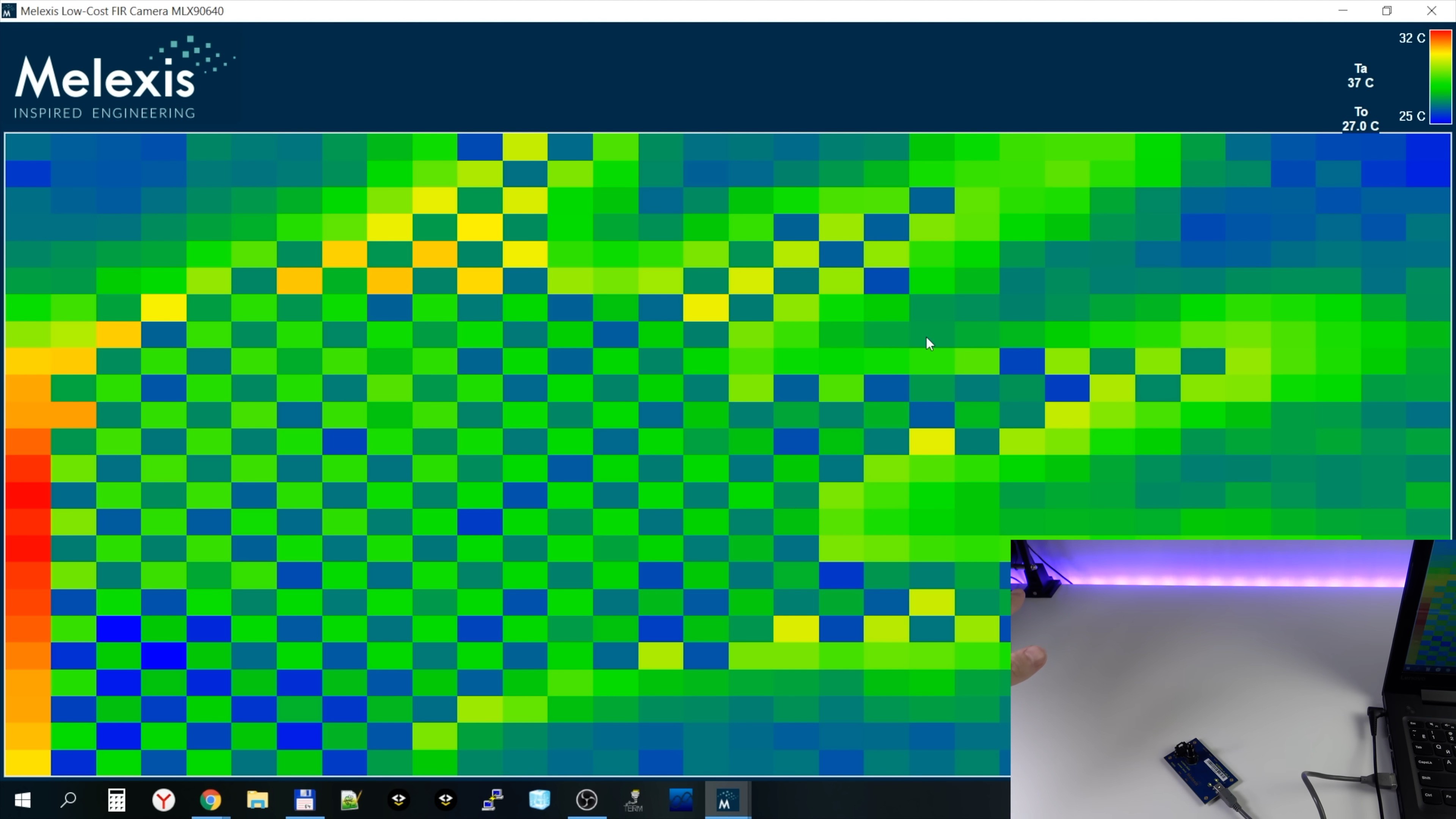
During a fast movement (FPS = 4 Hz is selected), we see a characteristic “checkerboard defect” on the thermogram, associated with the order of scanning the matrix by the sensor:

Now let's try a frequency of 32 Hz. As you can see, the image has become noisier:

This effect is mentioned in the documentation. The higher the frequency of collecting thermograms, the higher the thermal noise of the pixel. The dependence is approximately the following: the noise increases by 0.1 degrees with each Hz of frequency (for the sensor version with FOV 55).

It turns out that with a data collection frequency of 64 Hz, we can get up to 5-6 degrees of noise.

Therefore, high acquisition rates of thermograms are not suitable for domestic use, but this allows the sensor to be used in systems where it is necessary to quickly determine the appearance and location of a very hot or cold object (if the temperature of the object is very different from the ambient temperature).

The noise also depends on the temperature of the measured object. The lower the temperature of the object, the...

Read more »

thermoimager_case.zip

V1.1 case model

Zip Archive - 232.00 kB - 03/04/2023 at 19:21

Download

  • 1 × LILYGO TTGO T4 v1.3 board
  • 1 × Melexis MLX90640 sensor
  • 1 × LP603060 Li-Po battery or equivalent

View all 3 project logs

Enjoy this project?

Share

Discussions

nigel wrote 07/14/2023 at 15:07 point

Federico, what happens when you select amd/x86 as the compiler kit? Does it work?

  Are you sure? yes | no

Federico Allegretti wrote 08/09/2023 at 13:49 point

got this:

[cms-driver] Error during CMake configure:     Error: Configuration failed.
    at CMakeServerClient.onMessage (c:\Users\Administrator\.vscode\extensions\ms-vscode.cmake-tools-1.14.34\dist\main.js:42823:33)
    at CMakeServerClient.onMoreData (c:\Users\Administrator\.vscode\extensions\ms-vscode.cmake-tools-1.14.34\dist\main.js:42796:18)
    at Socket.emit (node:events:513:28)
    at addChunk (node:internal/streams/readable:315:12)
    at readableAddChunk (node:internal/streams/readable:289:9)
    at Readable.push (node:internal/streams/readable:228:10)
    at Pipe.onStreamRead (node:internal/stream_base_commons:190:23)

in problems got:

CMake Error at CMakeLists.txt:5 (include):include could not find load file:

  /tools/cmake/project.cmake


  Are you sure? yes | no

nigel wrote 08/10/2023 at 14:24 point

Hi Federico, please see your private messages.   You need to start again using version 3.3 of esp-idf which is the one Ruslan used when he built the thermal imager. I have copied some very basic instructions - you will have to experiment a bit.

  Are you sure? yes | no

Federico Allegretti wrote 06/27/2023 at 12:17 point

Hello. trying to compile but got this error:

Error: Bootloader binary size 0x72b0 bytes is too large for partition table offset 0x8000. Bootloader binary can be maximum 0x7000 (28672) bytes unless the partition table offset is increased in the Partition Table section of the project configuration menu.

  Are you sure? yes | no

Ruslan wrote 06/30/2023 at 14:11 point

This is strange because other people have not encountered this error. Please tell me which project you are compiling? v1.0 or v1.1? Try v1.1 if not: https://github.com/rnadyrshin/mlx90640_thermoimager_v1.1

What development environment are you using? VSCode + ESP-IDF? What version of the ESP-IDF?

  Are you sure? yes | no

Federico Allegretti wrote 07/13/2023 at 15:03 point

hello.

vscode 1.79.2 + idf 1.6.4

thermoimager v1.1

  Are you sure? yes | no

nigel wrote 07/05/2023 at 09:18 point

I got a similar error because I had not selected the correct esp32 device. Click on the esp32 icon in the status bar at the bottom of Vs Code and make sure that 1) your project is selected 2) ESP32 is selected and 3) ESP-WROVER-KIT-3.3v is selected. Then try to build and flash again.  I also reduced the flash baud rate from 460800 to 115200.

  Are you sure? yes | no

Federico Allegretti wrote 07/13/2023 at 15:06 point

done what you suggest .. now i was asked to set the "kit" to build the code.

"Scan for kits" will provide no result

"unspecified" fail the build.

All others are amd/x86 compilers

  Are you sure? yes | no

nigel wrote 06/14/2023 at 09:48 point

Does anyone have a schematic of the hardware connecting the sensor to the 20 pin connector as I cannot see how it is wired up and which RCs to use from just the photos? Regarding the user below, I got 2.4" which I believe the case is modelled on but I am not 3D printing the case.

  Are you sure? yes | no

Ruslan wrote 06/14/2023 at 10:41 point

2 resistors are needed to pull up I2C bus (SDA and SCL) to +3.3V. The value of the resistors is from 1 KΩ to 10 KΩ.

The other 2 resistors (at the top of the board) are a voltage divider to measure battery voltage. The first resistor is 5.1 kΩ between VBAT and IO35. The second resistor is 4.7 kΩ between GND and IO35.

Pin SCL is IO26 on 20pin header, pin SDA is IO33 on 20pin header

  Are you sure? yes | no

nigel wrote 06/14/2023 at 21:31 point

Thanks, I will try.

  Are you sure? yes | no

nigel wrote 04/09/2023 at 17:50 point

Hi, I am interested in building this camera for monitoring of body temperature of hedgehogs and cats.  I also have the Melixes evaluation board with sensors but I want to use the camera without the computer. I am not a software person so I am not sure how to make the hardware work -- no readMe file.  Do I have to import the files into vsCode?  Then what is SDK for?  Also, how do I then program the

LILYGO TTGO T4 v1.3 board?  Sorry for all the questions but if I want to build it I would need more step-by-step instructions.  Also, the Russian battery is not available in the EU and I cannot find an equivalent.


  Are you sure? yes | no

Ruslan wrote 04/09/2023 at 20:03 point

That's right, LILYGO TTGO T4 v1.3 board.

You can choose any Li-ion or Li-Po battery, suitable in size and with a voltage of 3.7V.
The battery I used has the following dimensions:
Length: 60±1mm
Width: 30±1mm
Thickness: 6±1mm

To install the development environment, I recommend using this instruction:

https://github.com/espressif/vscode-esp-idf-extension/blob/master/docs/tutorial/install.md

After that, simply open the project folder with VSCode and click the compile button in the VSCode status bar. The button next to it writes the firmware to the TTGO T4 board (you need to select the correct COM port).

  Are you sure? yes | no

nigel wrote 04/10/2023 at 08:44 point

Thank you so  much for answers to my questions. I am waiting for delivery of LILYGO TTGO board. When I get it I will follow the instructions.  Hopefully everything will go okay.

  Are you sure? yes | no

arborealfirecat wrote 03/09/2023 at 20:11 point

Great project! Thanks for the breakdown.

I'm currently trying to replicate your project but have been unable to compile the firmware.

I'm using the esp-idf framework as a VSCode extension & compiling on Arch Linux.

Are you able to provide me with some pointers such as your esp-idf framework version?

I'm relatively new to compiling C for Arduino, so I've included the full build log at https://gist.github.com/arborealfirecat/407708501735f52fea28a26217ec6f92

  Are you sure? yes | no

Ruslan wrote 03/10/2023 at 13:28 point

i was using a rather old version of ESP-IDF (v.3.3.1)
Today i updated the project to ESP-IDF v4.4.3, please try: https://github.com/rnadyrshin/mlx90640_thermoimager_v1.1/tree/a2679fc66f4ca5bb4e832fe65e93f84e03494f88

  Are you sure? yes | no

arborealfirecat wrote 03/10/2023 at 14:58 point

Thanks, I've managed to compile the project after one slight change.

As my OS is case sensitive the includes for MLX90640_API on main.c line 7 and task_mlx.c line 5 had to be changed to uppercase.

Now I just need to figure out why flashing the device loops the following:

https://gist.github.com/arborealfirecat/f75e7e5843f8b0824e678cd235545940

  Are you sure? yes | no

Ruslan wrote 03/11/2023 at 19:54 point

Unfortunately, I do not have a thermal imager at hand right now to reproduce the problem on my own. The previous version for ESP-IDF 3.3.1 definitely worked without problems. I tried to create a clean project again and setup sdkconfig manually, please try it.
https://github.com/rnadyrshin/mlx90640_thermoimager_v1.1/tree/efd656abd166f2b459e9a2012034750bcf977479

  Are you sure? yes | no

eBender wrote 02/28/2023 at 20:29 point

Hey great project and form factor! not sure if i missed it in the description but could you post your code? i'm really interested in your de-interlacing solution, doing something similar. thank you!

  Are you sure? yes | no

Ruslan wrote 02/28/2023 at 20:33 point

Thanks! I have not published the code yet, but I will definitely do it when I finish the description of this project. I have to prepare the code for publication and upload it to github

  Are you sure? yes | no

eBender wrote 02/28/2023 at 20:34 point

sounds great, will keep an eye out!

  Are you sure? yes | no

Federico Allegretti wrote 02/28/2023 at 20:13 point

Hello. Got a mlx thermal I plan to bind to a raspberry pi pico.  Going to follow your project ;-)

  Are you sure? yes | no

Ruslan wrote 02/28/2023 at 20:29 point

Thank you

  Are you sure? yes | no

karelv wrote 02/24/2023 at 18:29 point

De-interlace filter helps to smooth the image when the object is moving.

The IIR filter reduces the noise for the pixel that do not see a temperature change, for example the background.

  Are you sure? yes | no

Ruslan wrote 02/24/2023 at 19:38 point

Thank you

  Are you sure? yes | no

[deleted]

[this comment has been deleted]

Ruslan wrote 02/24/2023 at 04:46 point

Unfortunately, Melexis does not publish USB protocol description for EVB90640-41. I see solutions like this:

- use the library for Windows from Melexis. https://www.melexis.com/en/documents/tools/tools-mlx90640-psf-software-library-pdf
- explore USB protocol and implement it yourself
- write your own firmware for EVB90640-41 or use another board instead

Maximum refresh rate of the full image is 32 Hz, but with this frequency the image will be quite noisy (noise is about 5 degrees)

  Are you sure? yes | no

Ruslan wrote 02/24/2023 at 04:54 point

Also i think EVB90640-41 is too expensive)

  Are you sure? yes | no

karelv wrote 02/24/2023 at 18:20 point

Agreed, but bare in mind it comes with a small field of view MLX90640 as well as MLX90641!

  Are you sure? yes | no

karelv wrote 02/24/2023 at 18:23 point

It has 64Hz refresh rate. So each 16ms there is a subframe available, and thus every 32ms there's a full frame available.

Remember that faster refresh rate yield in higher noise levels.

  Are you sure? yes | no

Ruslan wrote 02/24/2023 at 19:40 point

yes, I wrote about it in the text

  Are you sure? yes | no

Similar Projects

Does this project spark your interest?

Become a member to follow this project and never miss any updates