 Anders Nielsen
The concept is simple: Take integrated circuits out of the waste stream and reuse them to make the smallest possible environmental footprint of an electronics learning platform, that encourages real use in 2023 and beyond!
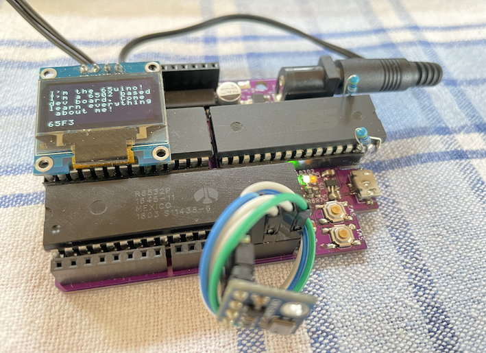
Since you can upload 6502 assembly code in a split second and immediately see the results on the OLED screen it's a great multitool that'll have you twiddling bits in no time!
By creating a stronger demand for used IC's we also encourage even more recycling of used parts, making an impact way beyond a single development board.
Teaching electronics and computer engineering often starts with a relatively high level "Hello World" example of blinking an LED using C/C++, abstracting away all the necessary parts that makes it "go". Concepts like CPU, ROM, RAM, I/O, stack, and instructions are all hidden away so it's easier to focus on the task at hand - blinking an LED.
If your goal is blinking an LED, then there's nothing wrong with that. This project takes a different approach by going back to the basics and giving students a stronger understanding of the individual system components by giving the opportunity to understand what each IC does and why it's needed in the system.
Limiting RAM and ROM (severely) also makes high level languages like Python or Arduino C less appropriate and encourages the use of assembly language instructions - even though the cc65 compiler will do a nice job for the 6502.
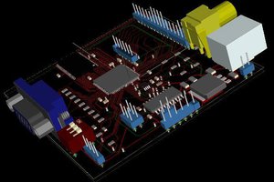
*The board uses an Arduino-compatible form factor but is not compatible with the Arduino IDE(yet anyway). This means that many "shields" or add-ons will be compatible. (If they don't have particularly high demands for clock speed or RAM).
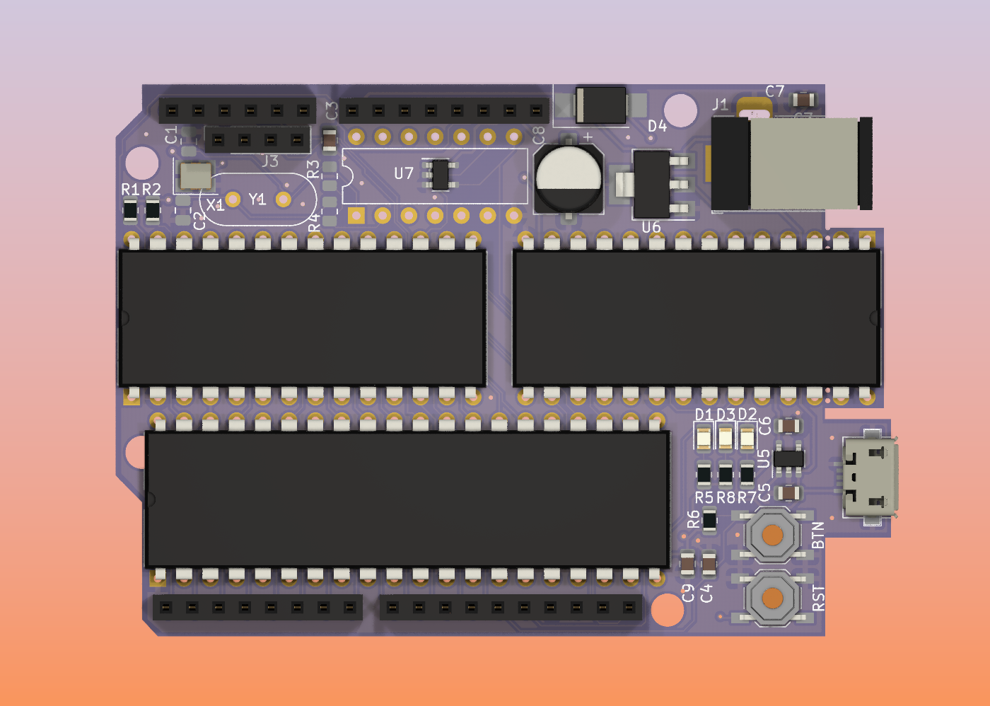
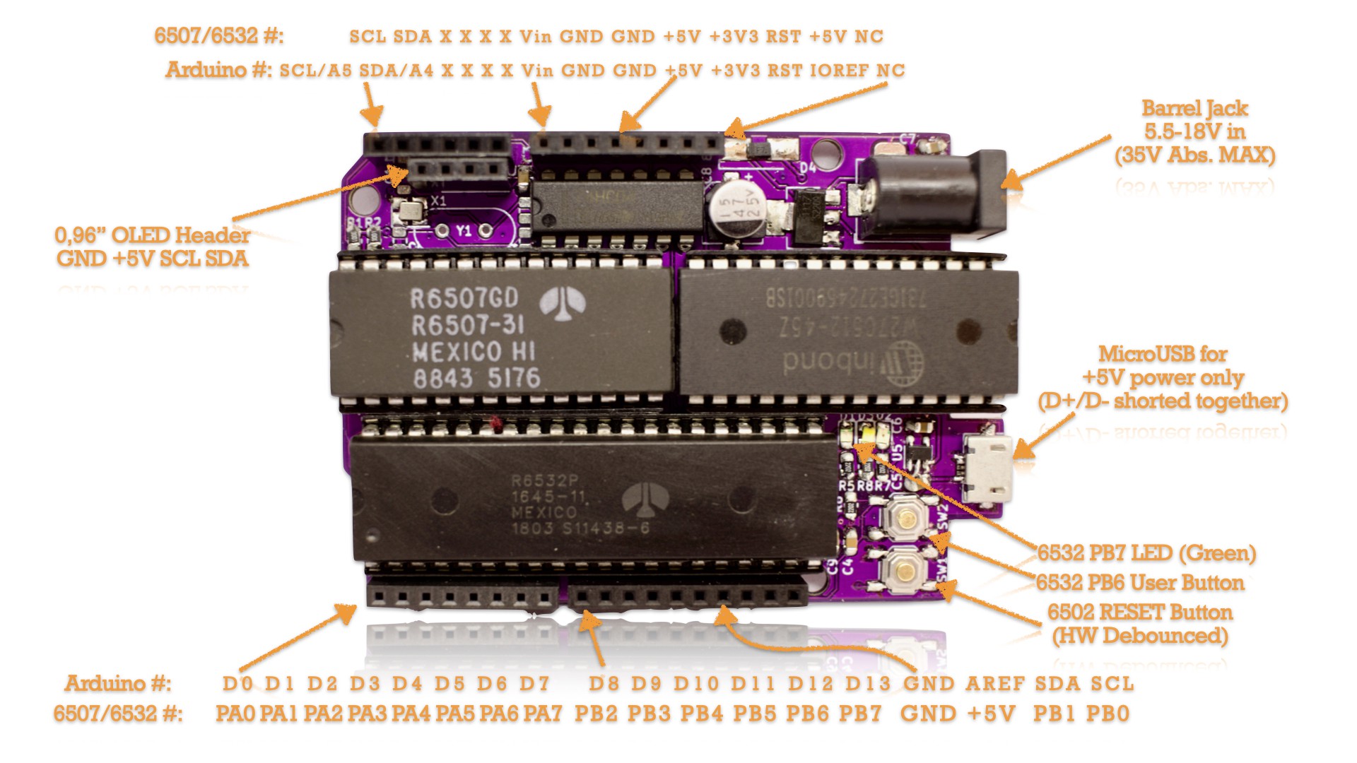
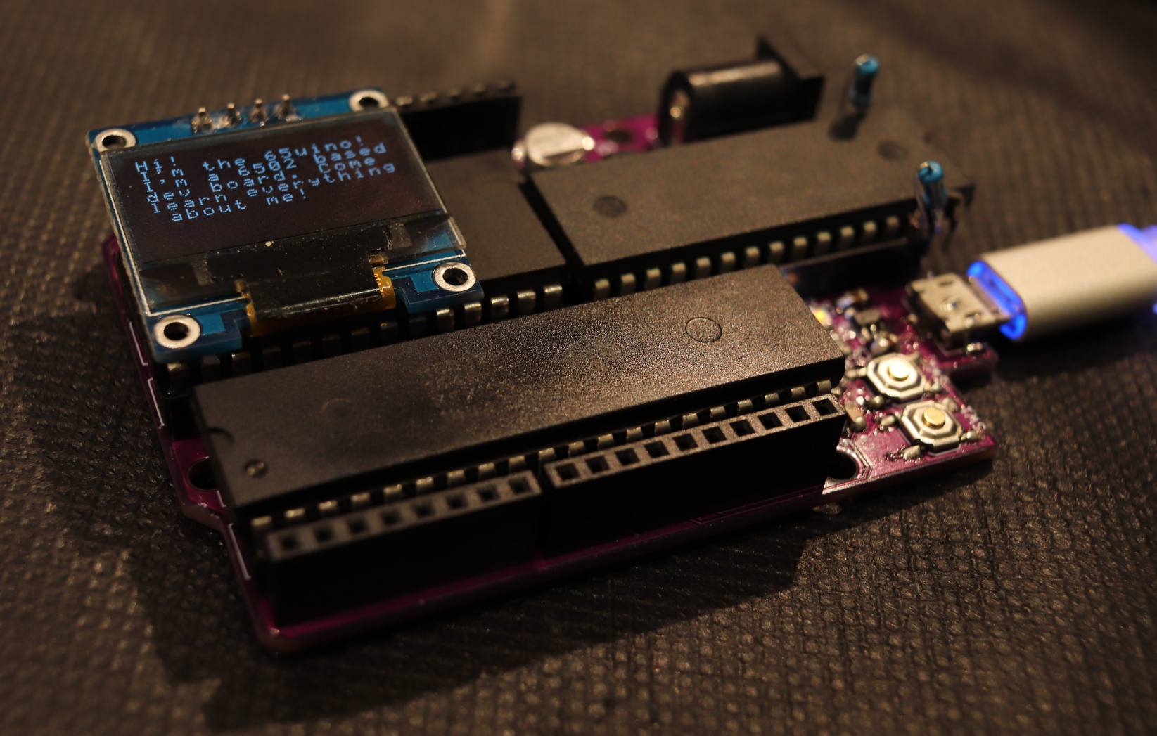
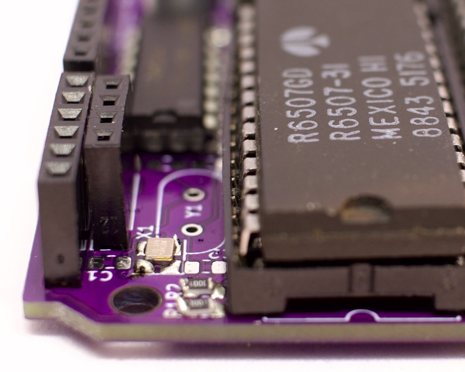
Since a complete 6502 based microcomputer, like an Apple II or my #ABN6502 SBC R1, usually takes up quite a bit of space the 65uino uses the 28 pin 6507 microprocessor instead of the 40 pin 6502. Inside the package you'll find the same silicon as a 6502, but with less pins broken out to the DIP package.
Features of the 65uino:
- 6507 Microprocessor running at 1 to 3 MHz
- 6532 RIOT chip - 128 bytes of RAM, two 8 bit I/O ports and a hardware timer
- Serial bootloader to allow fast coding without re-burning ROM
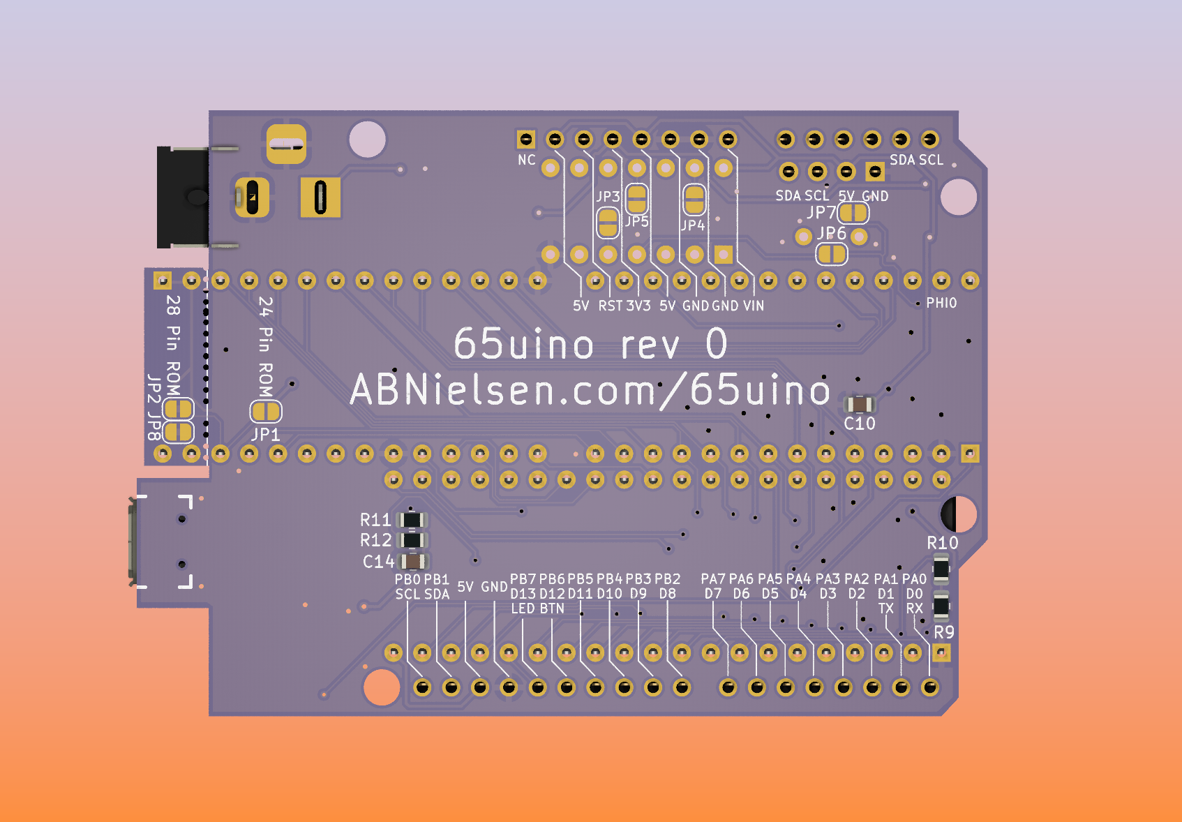
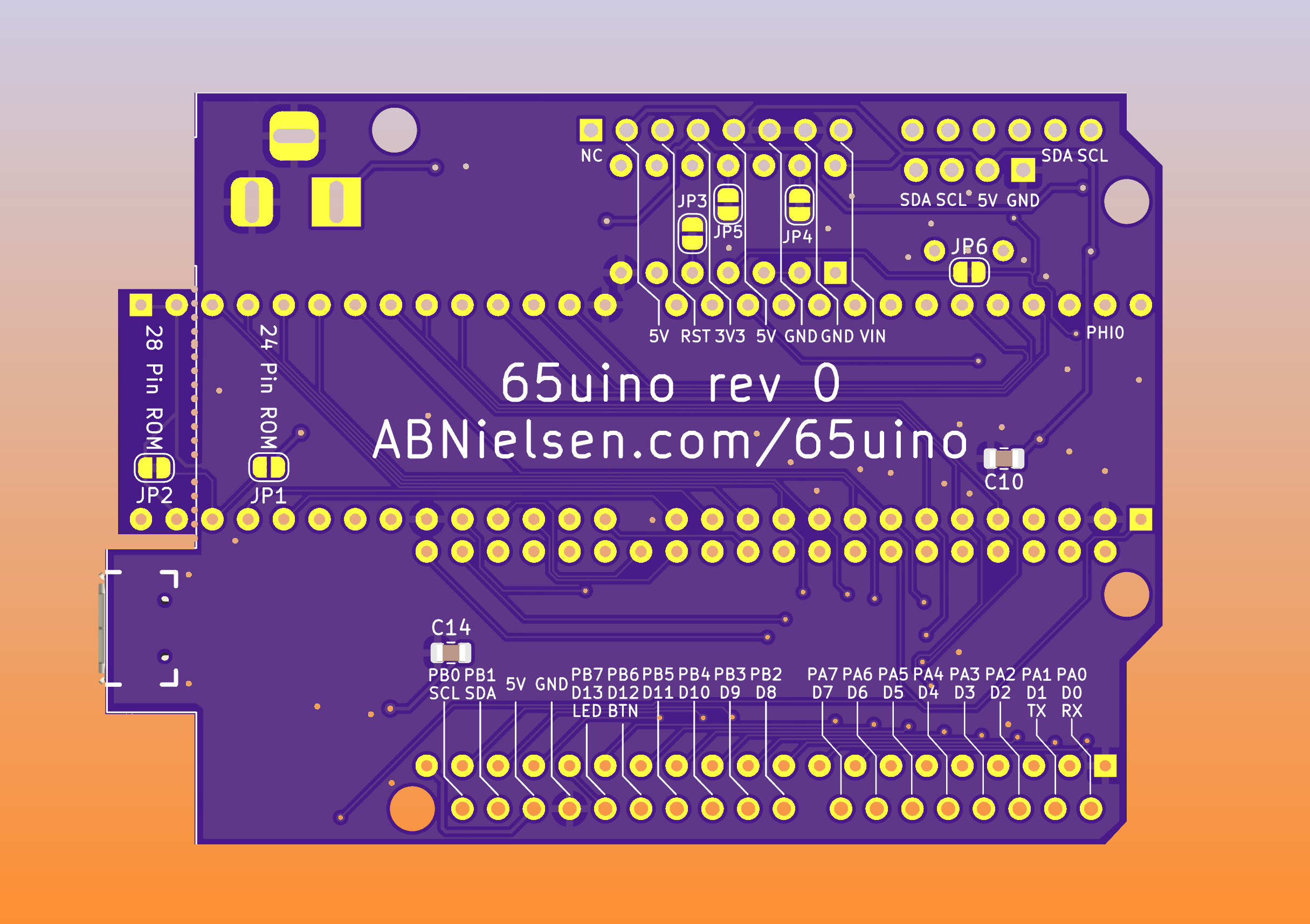
- 4K of addressable ROM - PCB design accepts either a 24 or 28 pin EEPROM/EPROM/PROM. To be compatible with Arduino cases and footprint the extra 4 pin section of ROM can be broken off the PCB.
- Onboard 3v3 and 5V regulators
- Onboard LEDs for power rails and "D13"
- Onboard reset and user pushbuttons
- I2C, SPI and UART is implemented in software
- Socket for 0.96" OLED i2c screen (and it works great!)
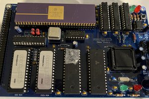
This project was inspired by my "Single Breadboard Computer". If you wan't to know more about the general philosophy and how to program a "bootloader" onto the 65uino, have a look at this video about the project that inspired it.


 Ross Bamford
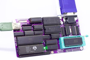
 PK
PK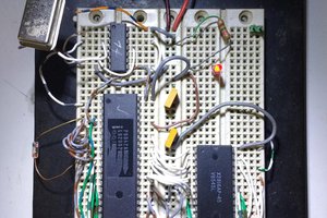
 Ken Yap
What editor and compiler was used in the video ??