 Lee Hart
Once upon a time, microcomputers were simple and easy to understand. So simple in fact that a kid like me, with no computer experience whatsoever, could actually understand them, build them, program them, and put them to work in his very own projects! My first computer was the COSMAC 'ELF', built from an article in the August 1976 issue of Popular Electronics magazine. It used the RCA 1802; an exceptionally easy to use microprocessor. The ELF taught me about computing, and got me started on a career in engineering.
Today's computers are far more powerful than the 1802. But they have also become so complicated that almost no one can build them, or truly understand how they work. They come on pre-assembled boards, and require a powerful PC to download pre-written programs to do anything. The opportunity to learn from the bottom up is missing; it's as if the lower rungs of the ladder have all been cut off, so you have to somehow start at the top.
The MemberChip Card is my attempt to return to the basics. It's the "bicycle" of computers; simple enough so someone with no prior experience can get started, build and program it, and learn about the fascinating world of electronics and computing!
Hardware
- CPU: RCA CDP1802ACE microprocessor
- Clock: 4 MHz ceramic resonator
- Memory: 64k (32k bytes RAM, 32k bytes EPROM)
- I/O:
- 4800 baud TTL serial port (for use with USB-serial adapter)
- 20-pin I/O expansion connector (with data bus, R/W, and I/O port select strobes)
- one 1-bit output (with red LED, for serial output)
- four 1-bit flag inputs (one with green LED, for serial input)
- one interrupt input - Connectors:
- 6-pin power+serial connector (mates with USB-serial adapters)
- 20-pin expansion connector with power, ground, and I/O signals - 100% through-hole construction (no surface-mount)
- Size: 2-1/8" x 1-3/8" x 5/8" (55 x 35 x 15 mm)
- Power: 3.6v to 5v DC at 2-3ma (depends on whether the LEDs are lit)
- Aroma: A hint of curiously strong peppermint
Software
- Standard ROM:
- Machine-language monitor to examine/change memory and registers
- RCA floating point BASIC3
- Vintage Adventureland game by Scott Adams - Advanced Elf-OS ROM by Mike Riley:
- MINIMON monitor program
- EDT/ASM mini editor/assembler
- VISUAL/02 visual debugger
- Integer Tiny BASIC (a classic from the 1970's)
- FORTH (an interactive stack-oriented programming language)
- LISP ( a pioneering programming language still used today)
- VTL-2 (a Very Tiny Language, even simpler than BASIC)
How did I get it so small? Here's the trick: It uses just one normal 2-sided PC board, but with parts mounted on both sides, to effectively double the space. They are carefully positioned so their pins miss each other, and are accessible for soldering. The PCB and schematics are also old-school; they were produced with last-century OrCAD software running on a 30-year-old PC.
The MemberChip card itself has a small amount of I/O for simple projects. But you can add expansion cards to greatly expand it. Here is an example of an I/O expansion card built by Herb Johnson using the 8255 (or 82C55). It adds three 8-bit expansion ports.
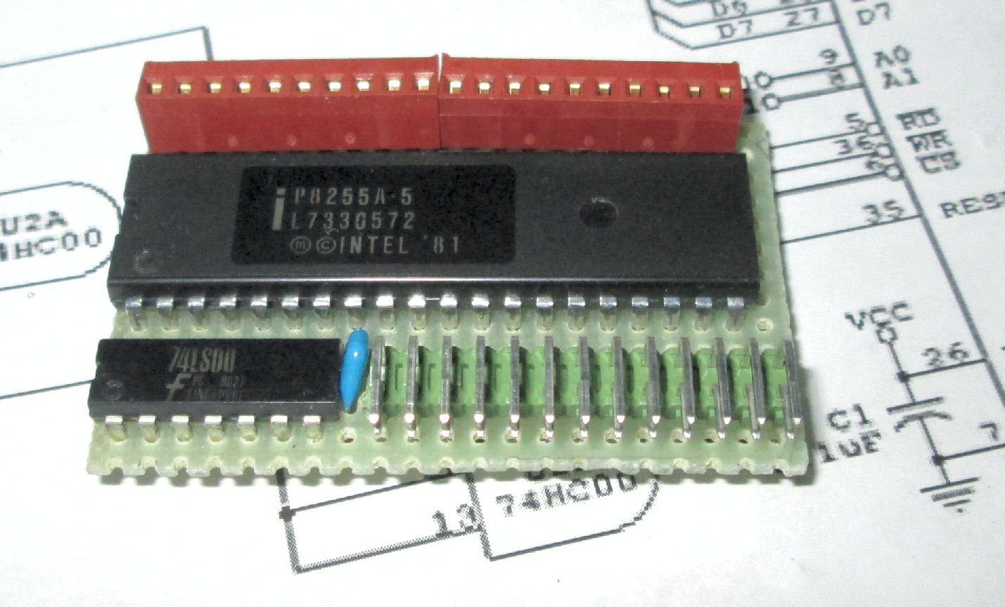
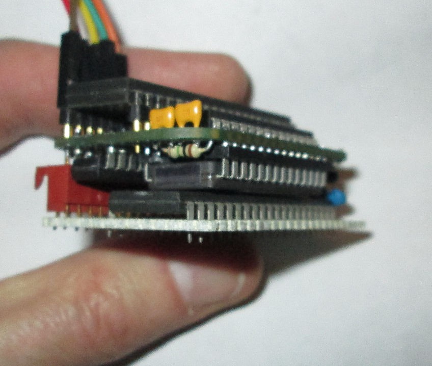
The schematic for it is shown in the gallery above. The red connector plugs into the 1802 MemberChip card expansion port, and the dual right-angle pin header at the bottom brings out power, ground, and the 24 I/O port pins. It was hand-wired on a piece of perfboard. Below is a photo of it plugged onto the 1802 MemberChip card to make a very compact 2-card stack.


 Bernhard "HotKey" Slawik
 Foxchild
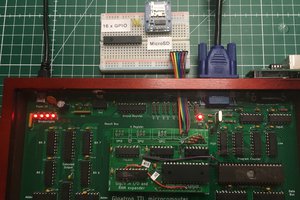
 Marcel van Kervinck
Loving your concept and idea Lee, kids need better accessible entry into tech, engineering, programming and IT and this looks a real cool way to tap into their curiosity. have followed, would be great if you could follow me too 🙏 hackaday.io/zxfan