Close
0%
0%

G-EDM

Sinker EDM with drill chuck and multi-toolhead for cutting and drilling metal

Similar projects worth following
The G-EDM is a fully automated one axis sinker EDM machine that supports different kinds of electrodes like brass tubes or brass sheets
and is highly customizable.

It can fit almost any kind of N-channel mosfet to support higher currents and the pulse generator PCB can easily handle 10 Amps of constant current.

It uses 3D printed parts where it is possible.

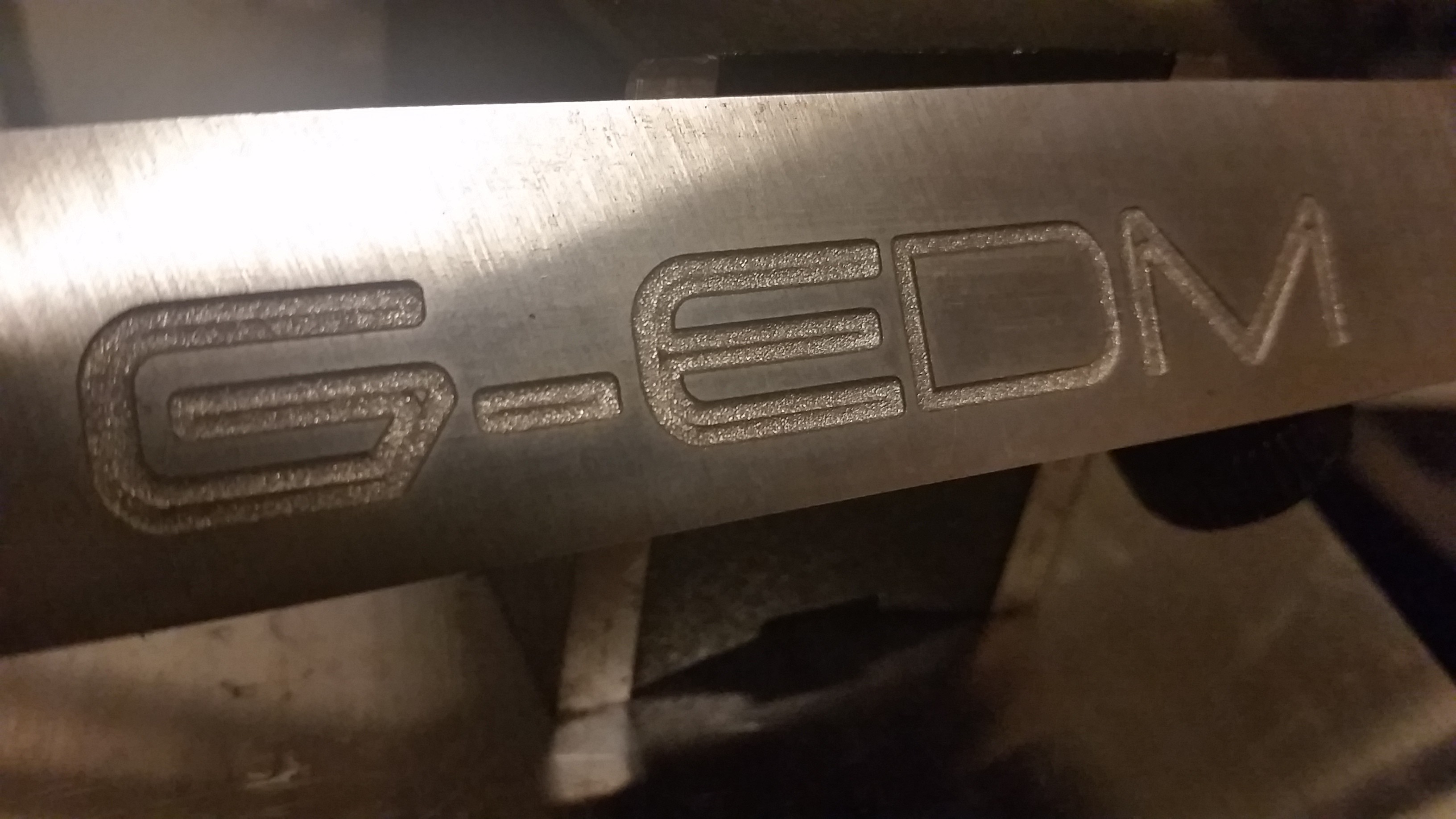
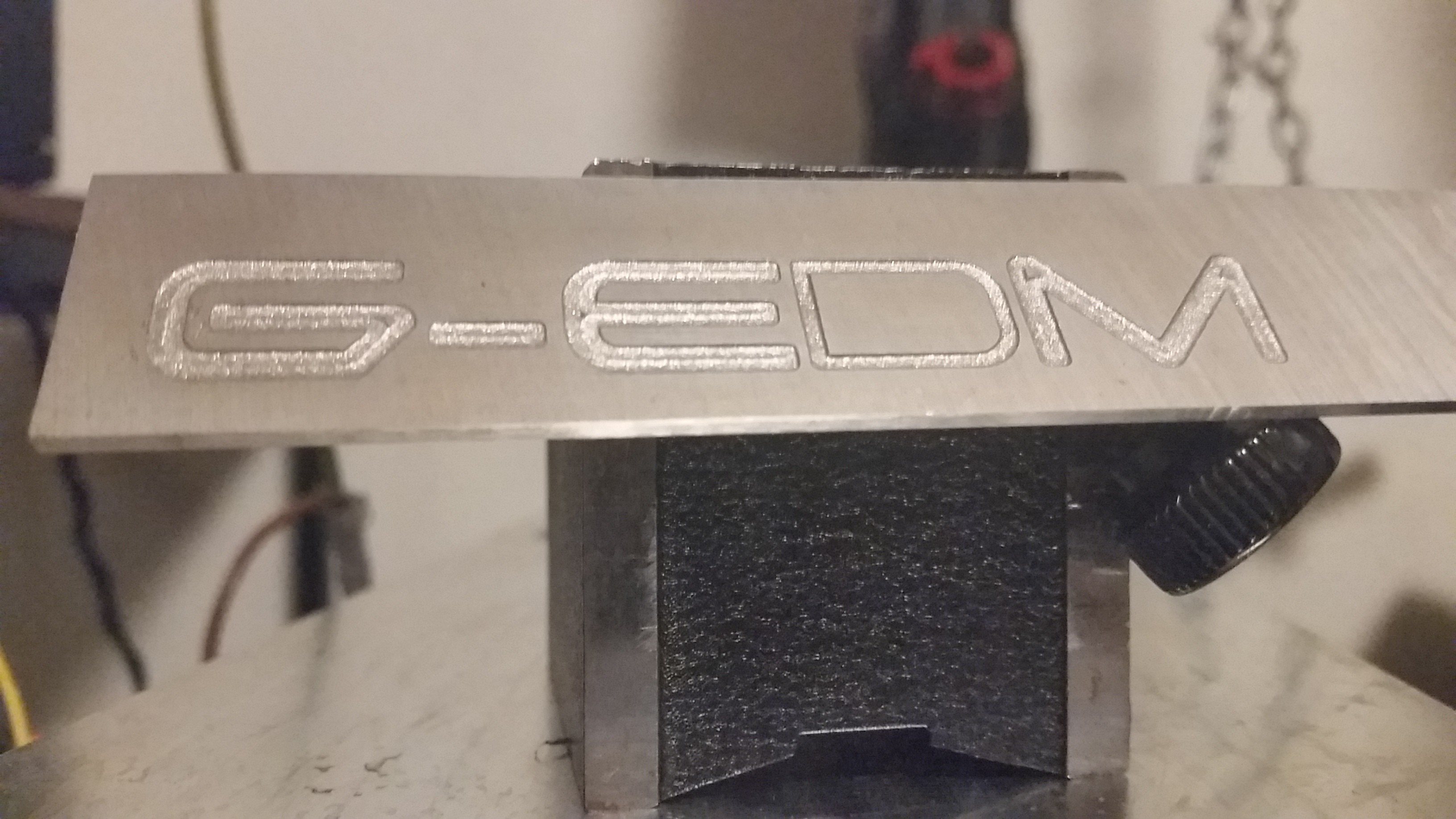
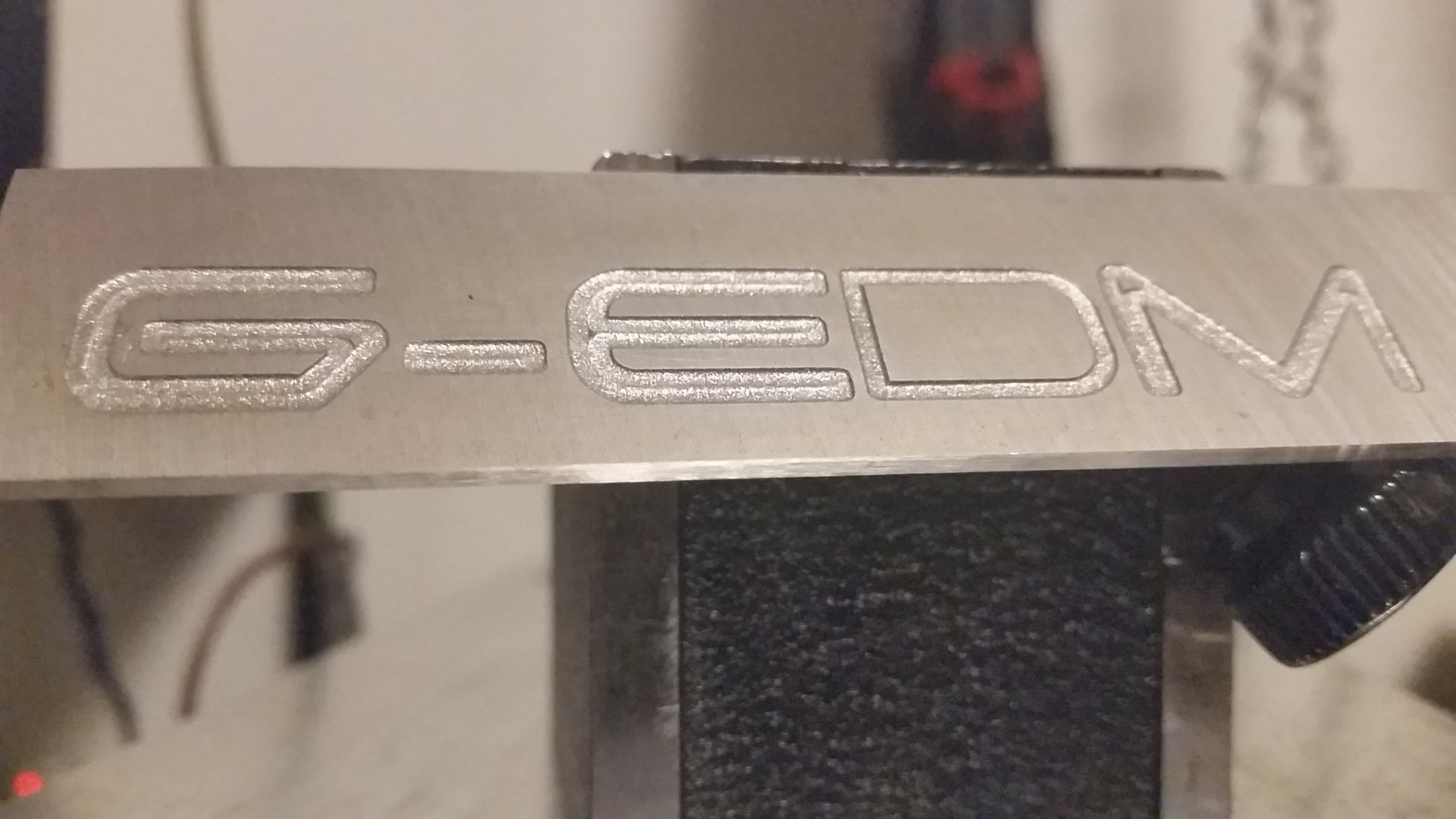
The G-EDM ( new video )

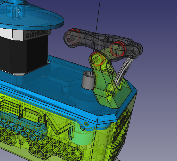
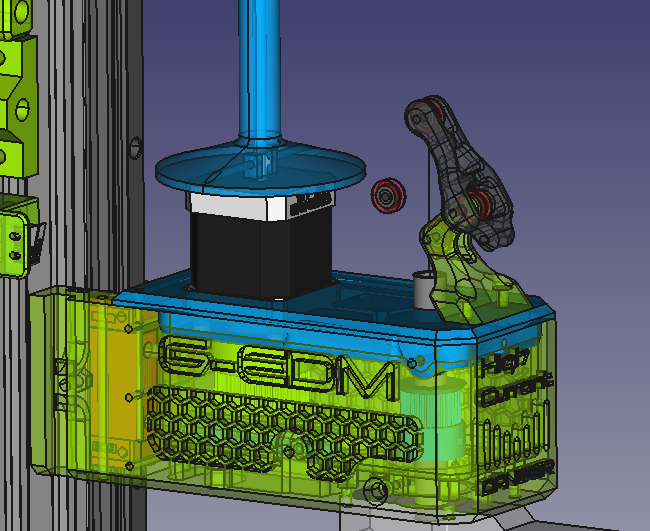
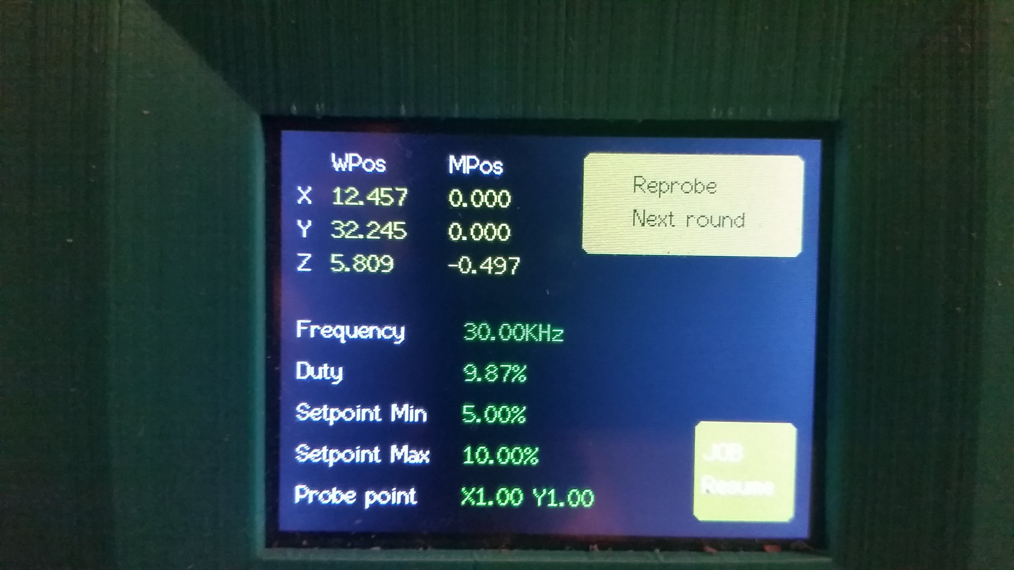
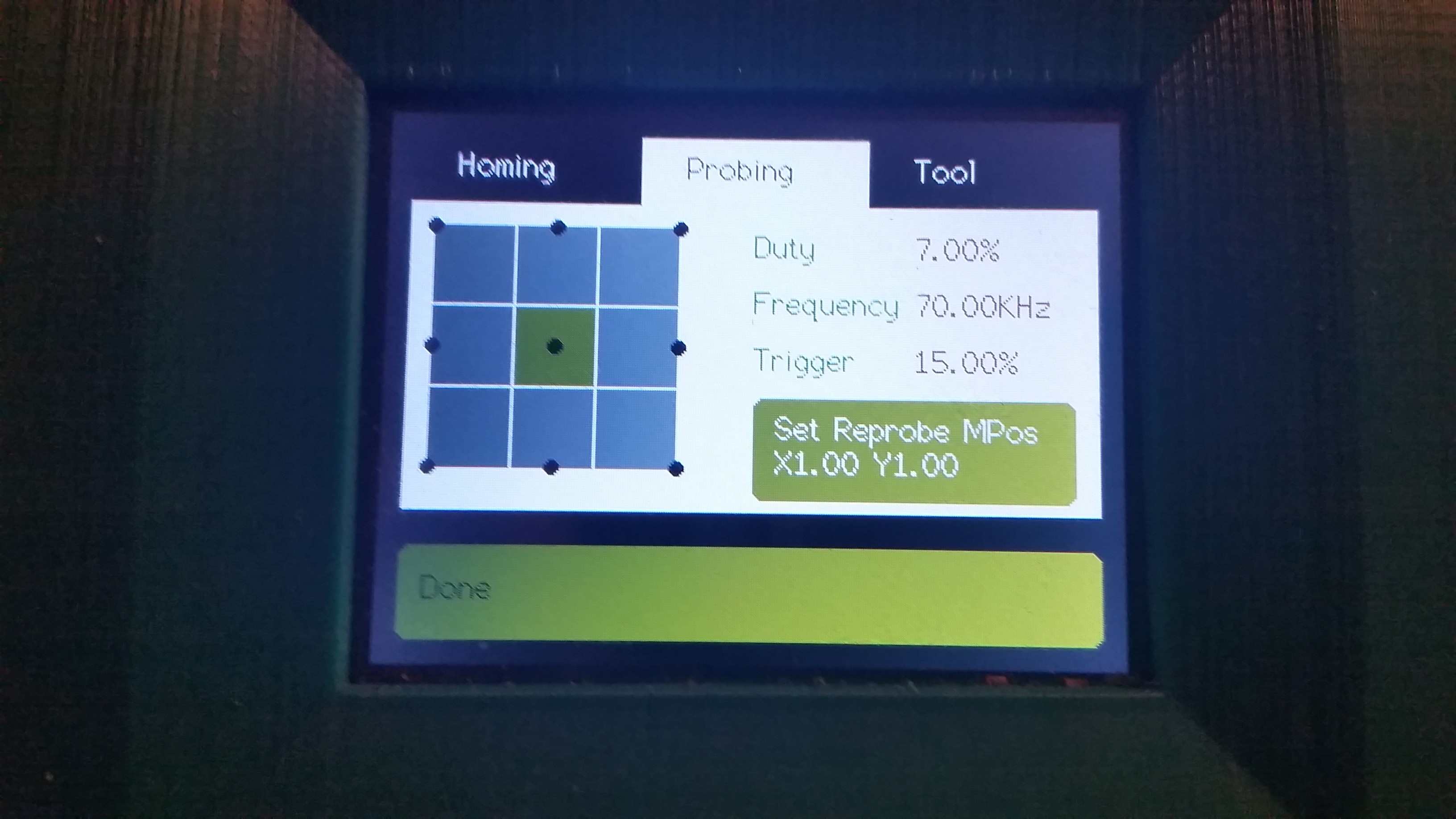
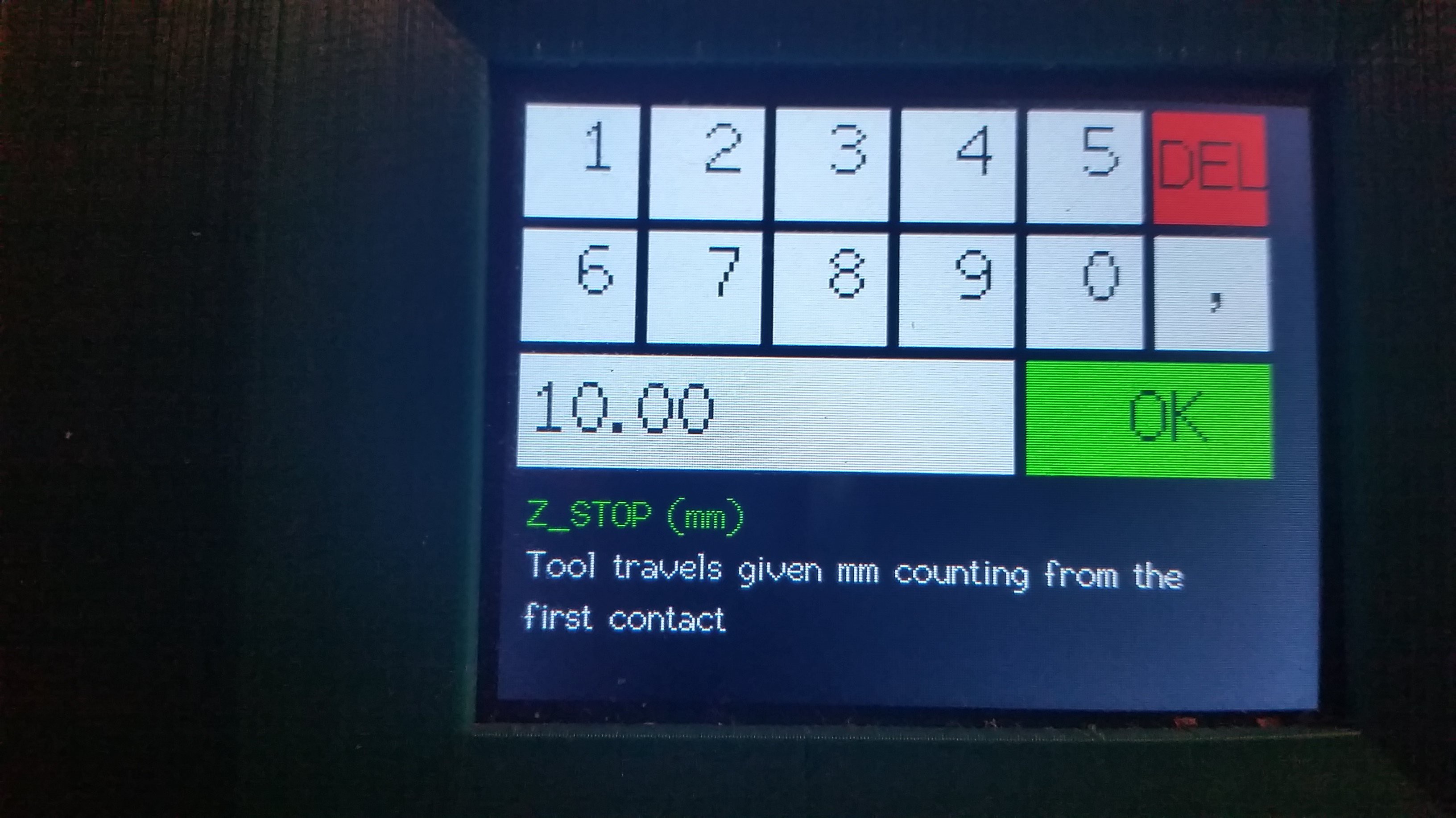
The final version of the control panel:
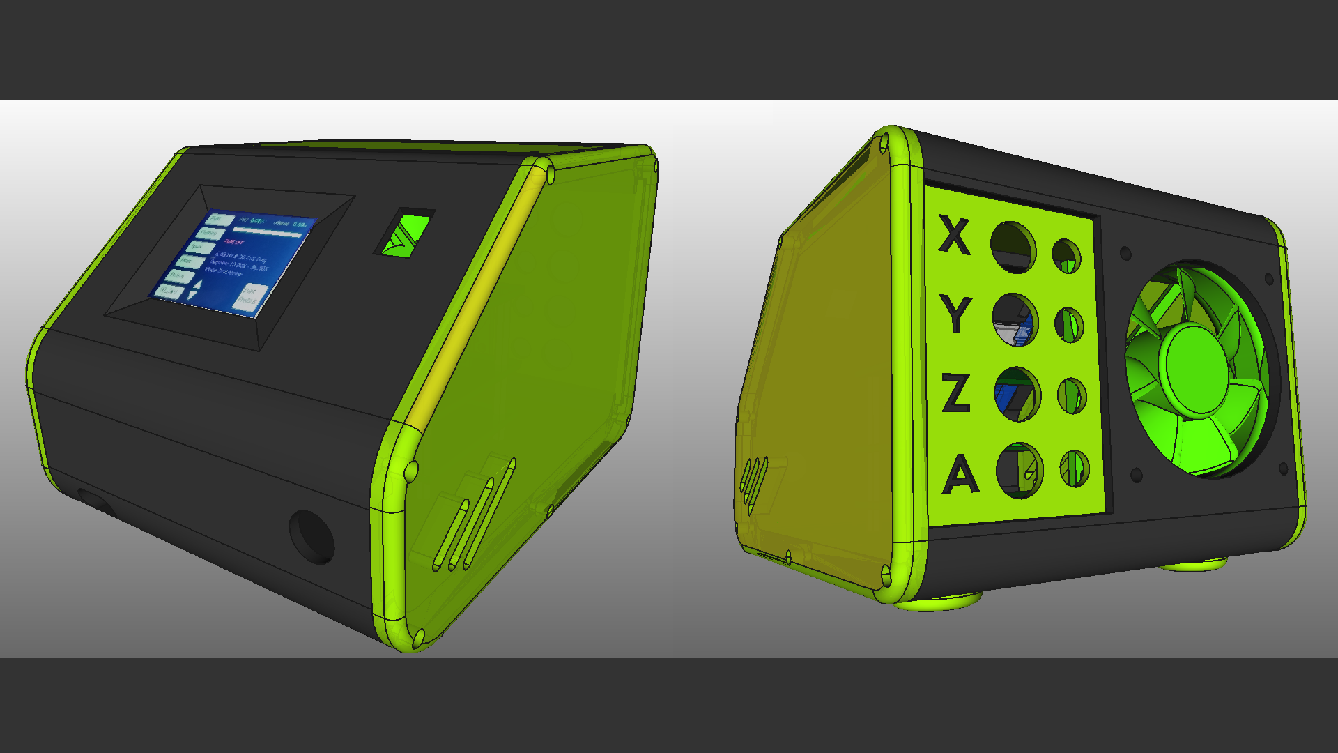
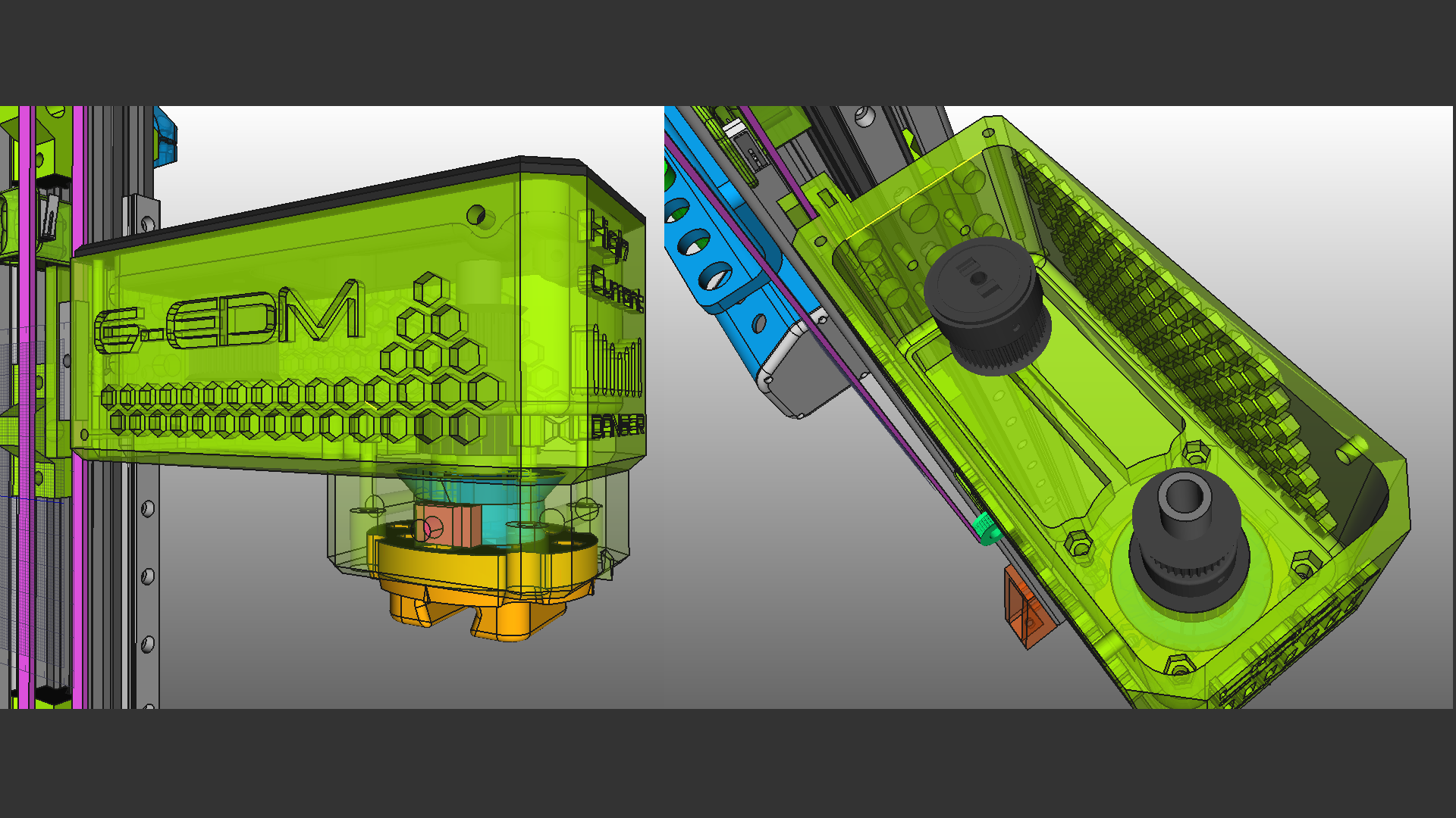
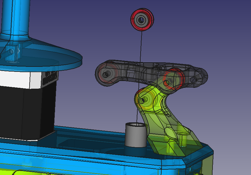
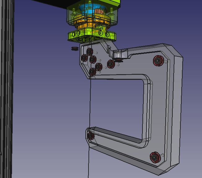
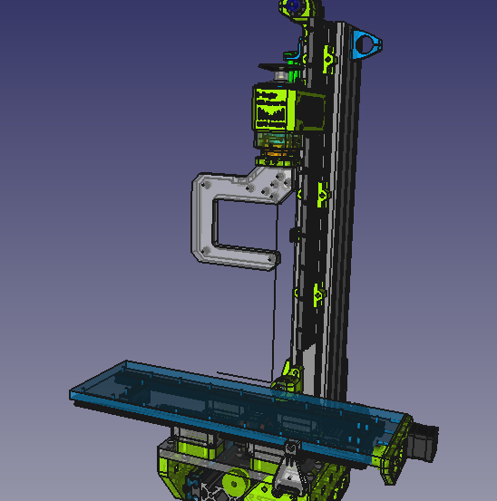


And more details:


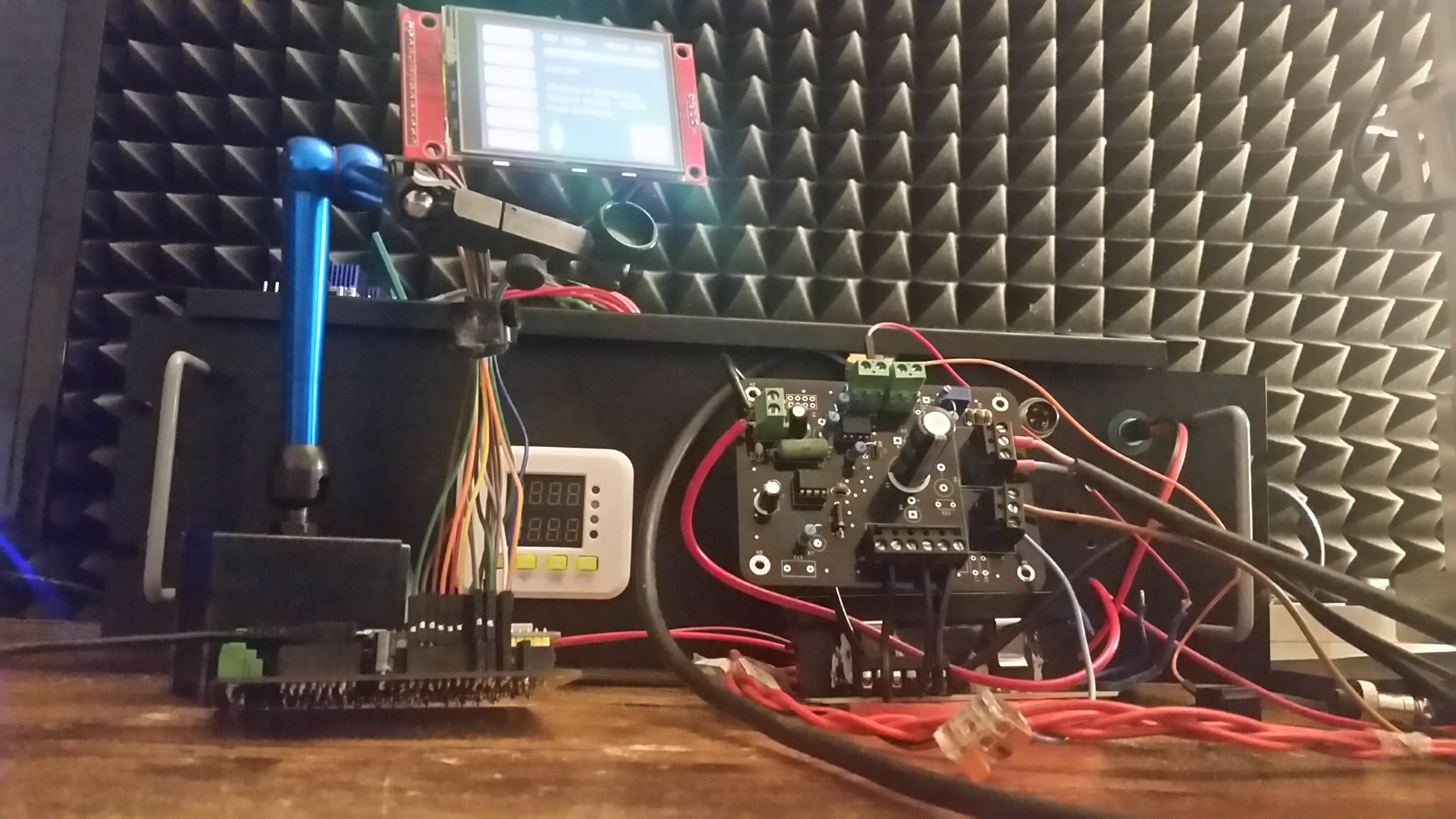
EDM can create a lot of EMI noise and therefore the spark generator needs to be in a shielded enclosure. But even the electrode and the spark itself create noise.

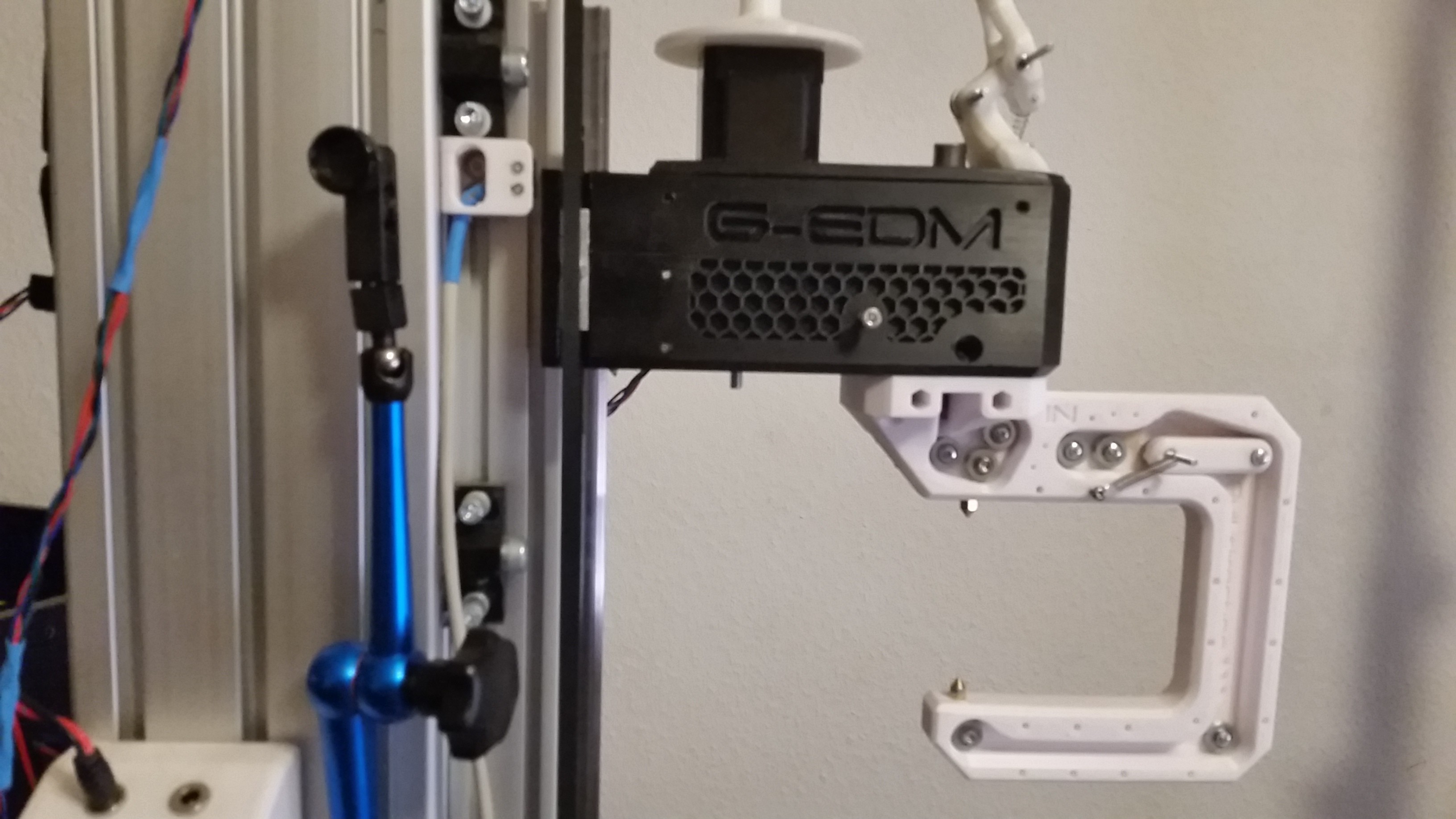
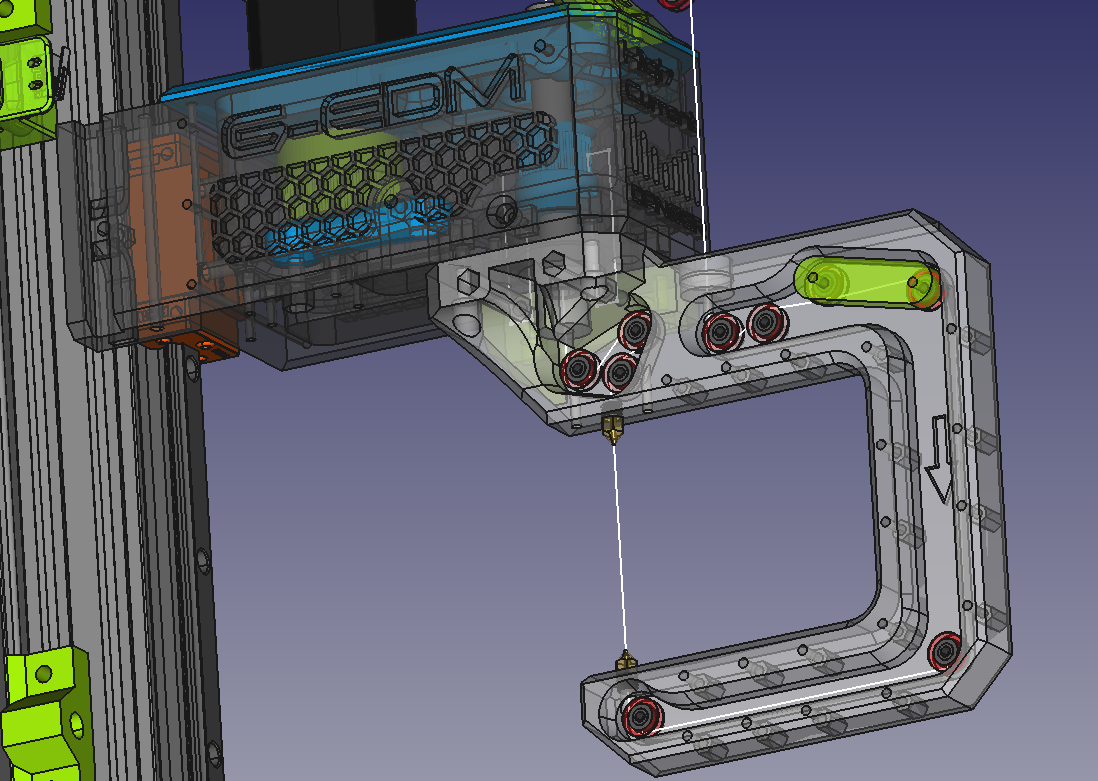
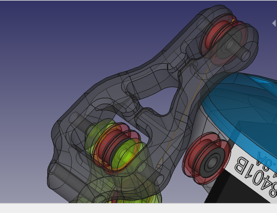
In the first builds the negative spark wire was mounted to the rotary drill chuck within the tool head. But this converted the electrode into a antenna with enough power to shut down the communication between the ESP and the display.

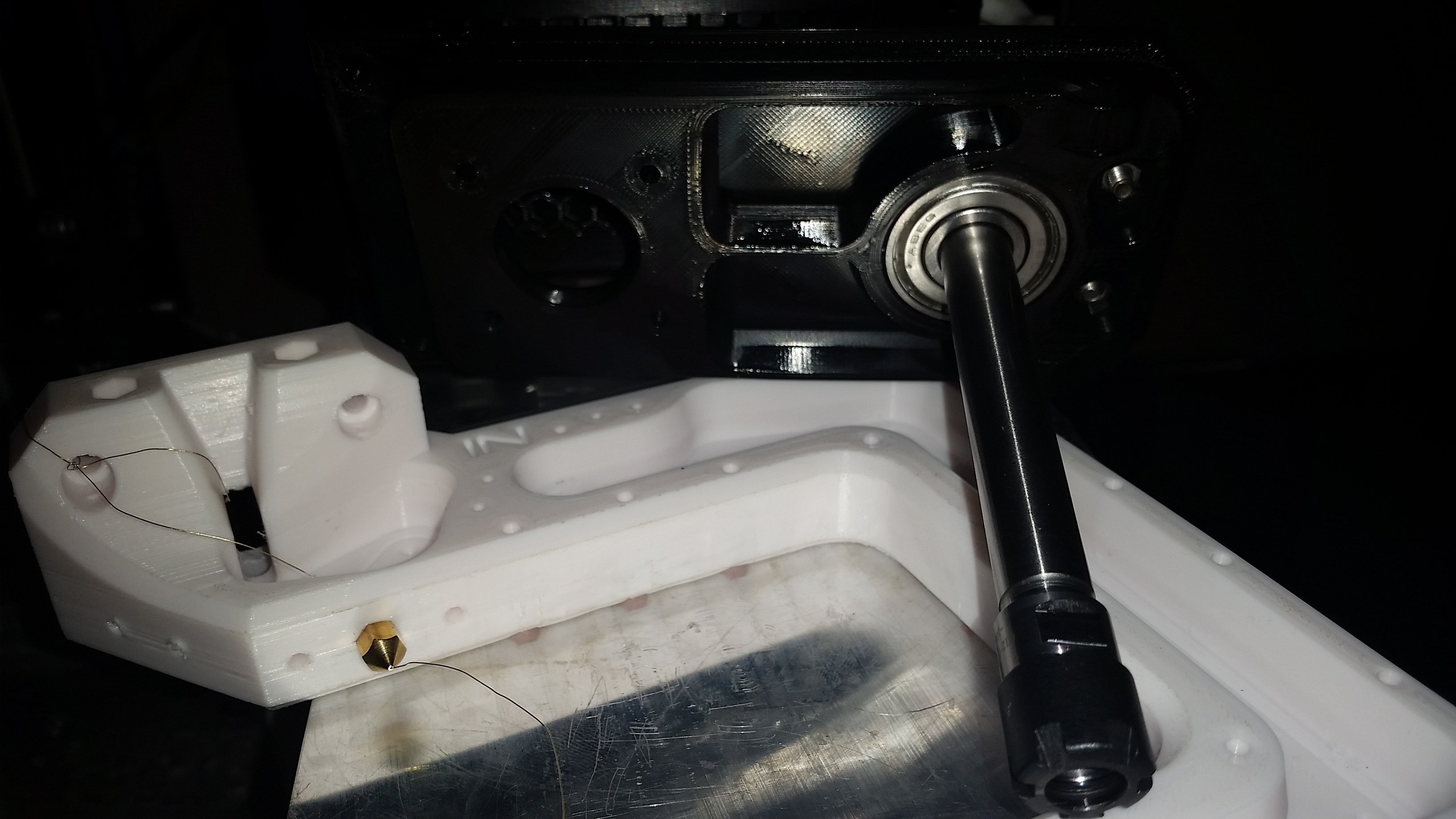
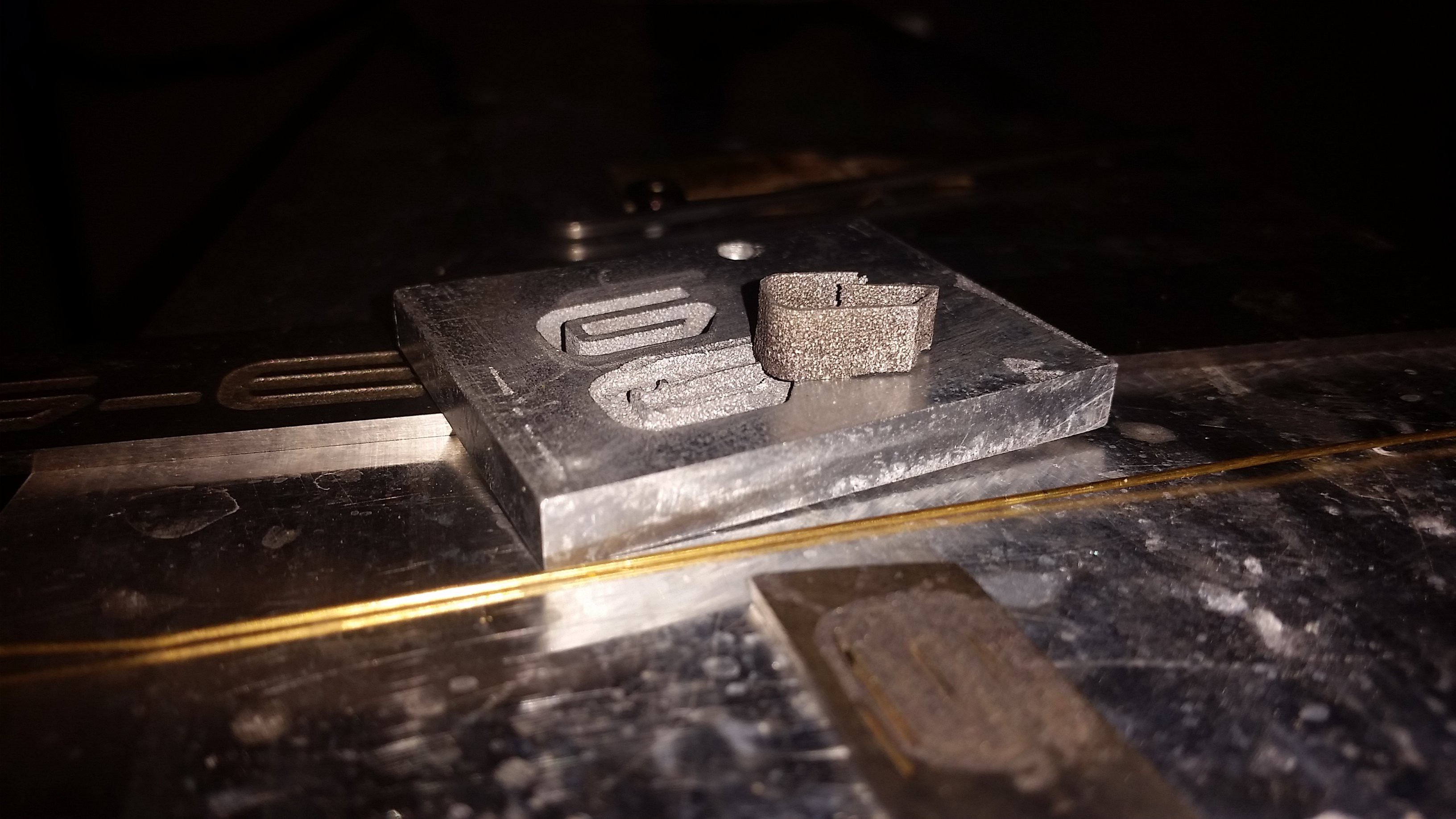
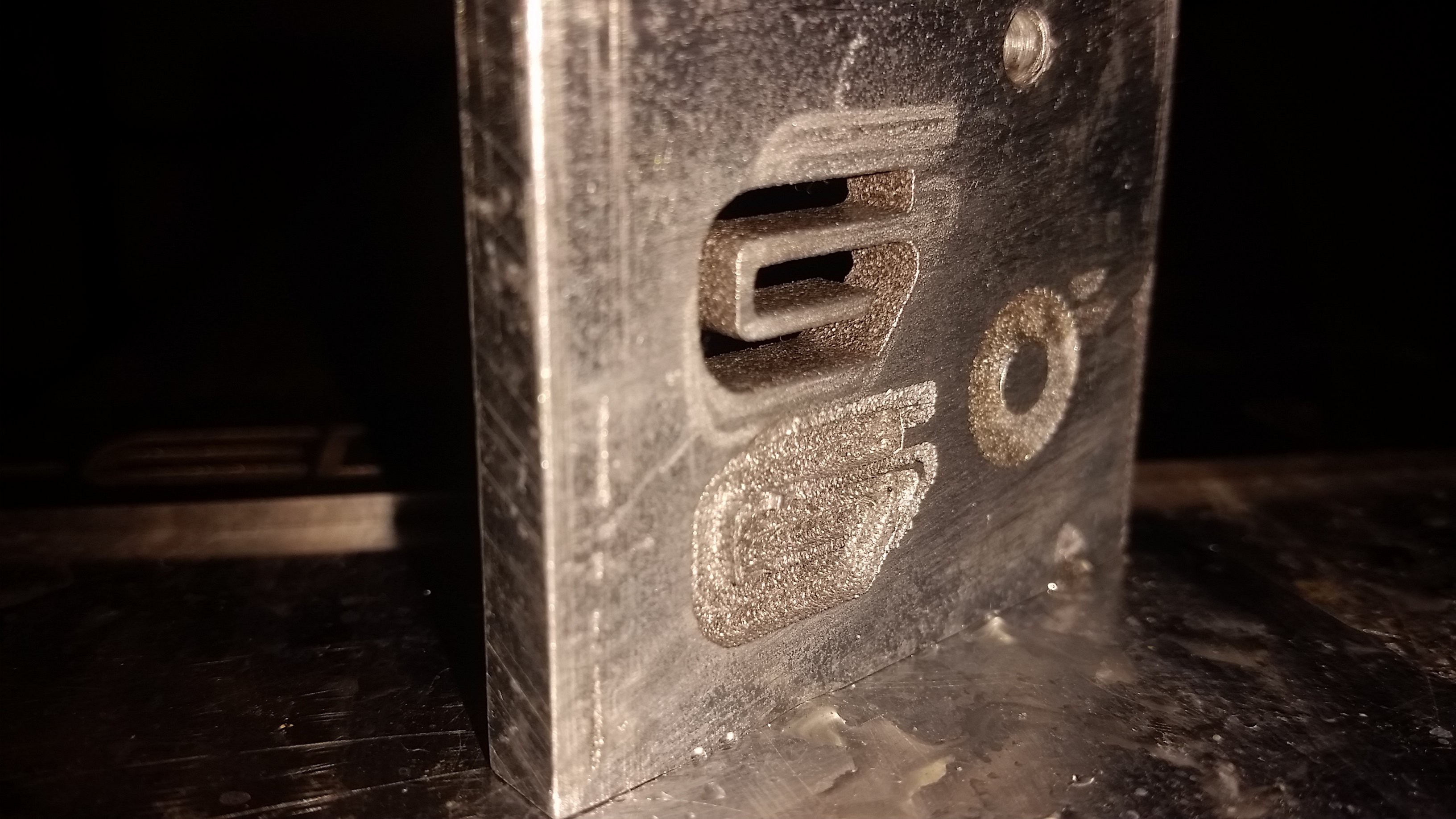
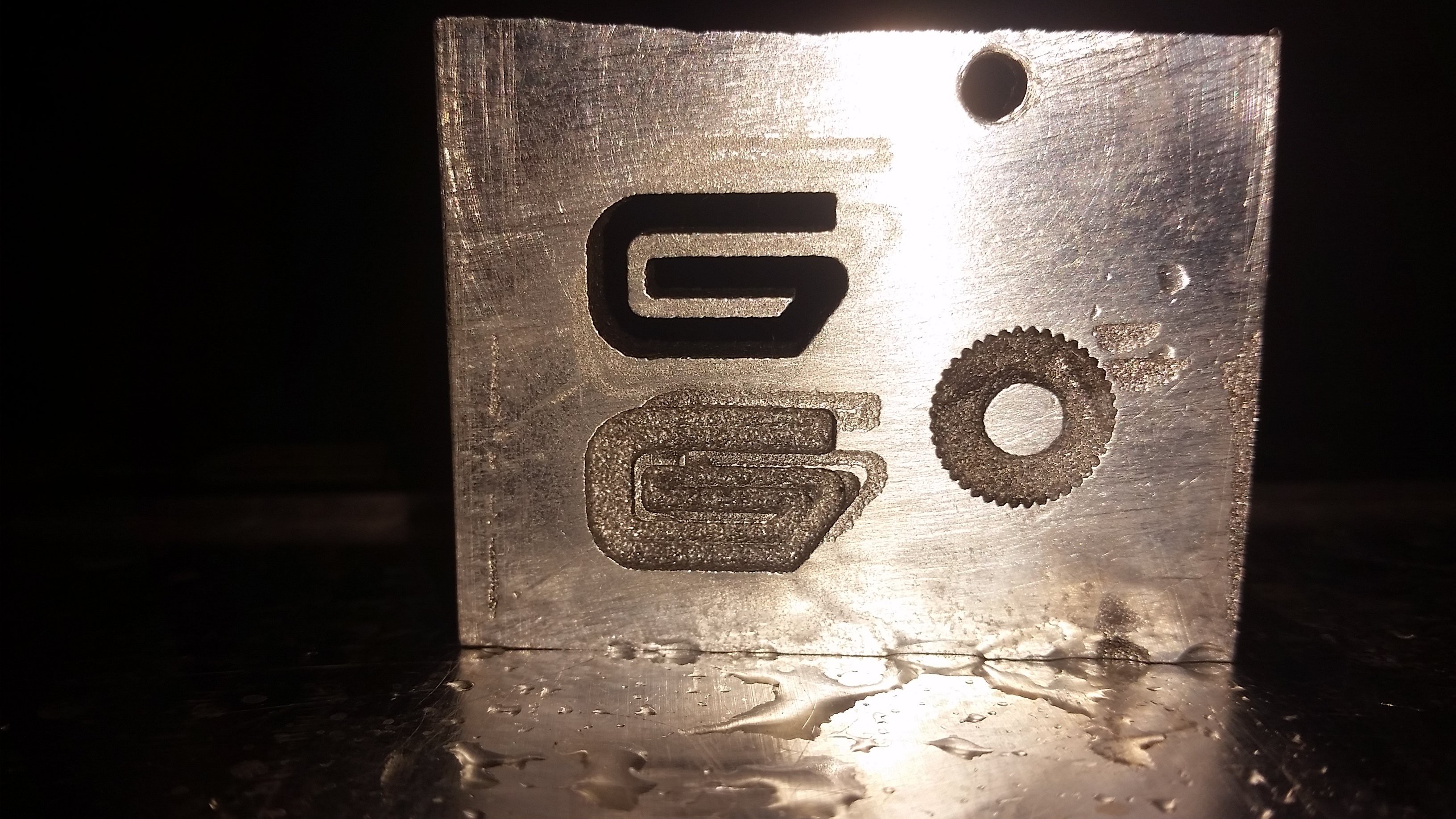
This highly depends on the Amps used, the duty cycle of the pulse and the length of the electrode but I decided to just connect the electrodes as close to the work piece as possible.

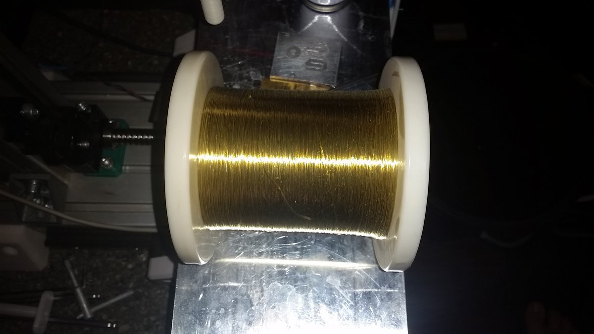
For round electrodes the blank wire is wrapped around them and for sheets alligator clips are good.

It doesn't look as good as the integrated contact but it reduces the noise a lot.

The pulse generator is a pretty basic and flexible concept that is easy to replicate. A 65v switching PSU is connected to a DPM8605 step down module that will provide 0-60v and 0-5A.

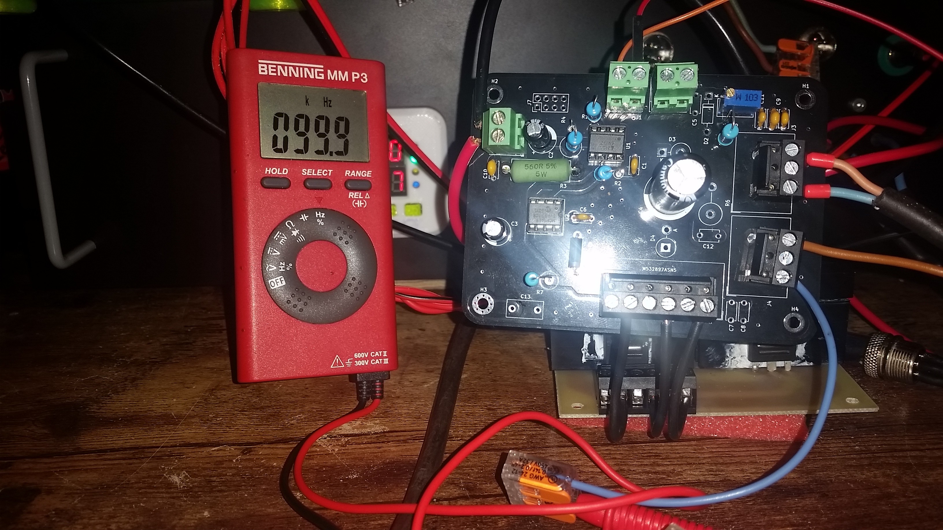
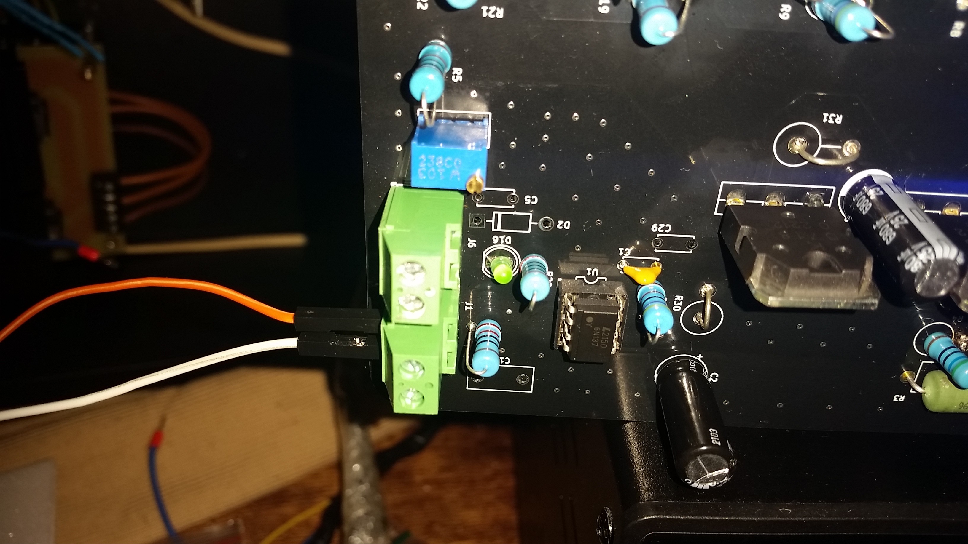
The output of the DPM8605 is then connected to the pulse generator PCB which is basically just a Mosfet gate driver, some capacitors and a voltage divider for the feedback signal.

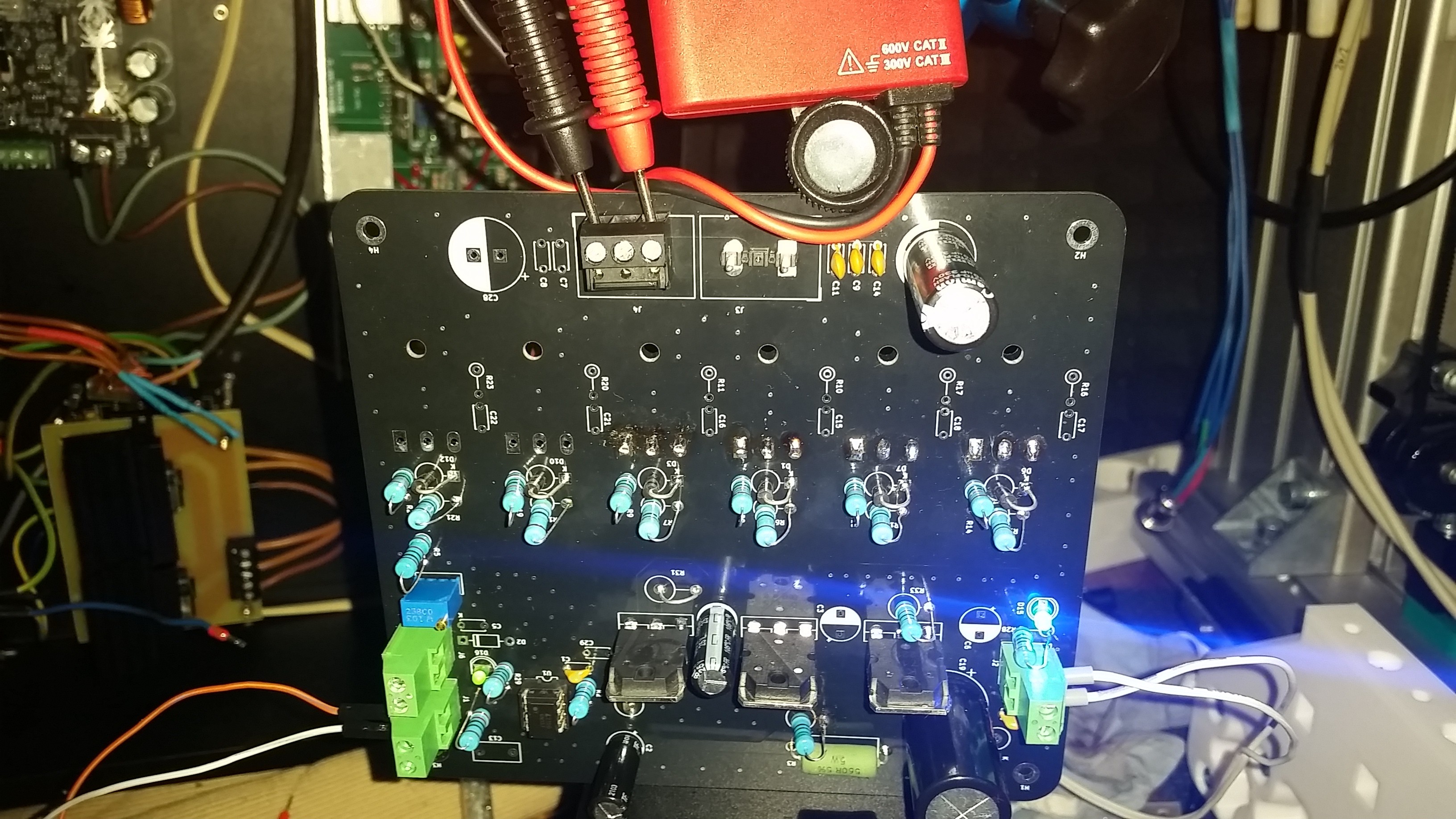
This is the pulse generator PCB ( prototype ) wired up for some basic tests.

At the moment there are two working versions of the pulseboard that drives the sparks of the G-EDM.

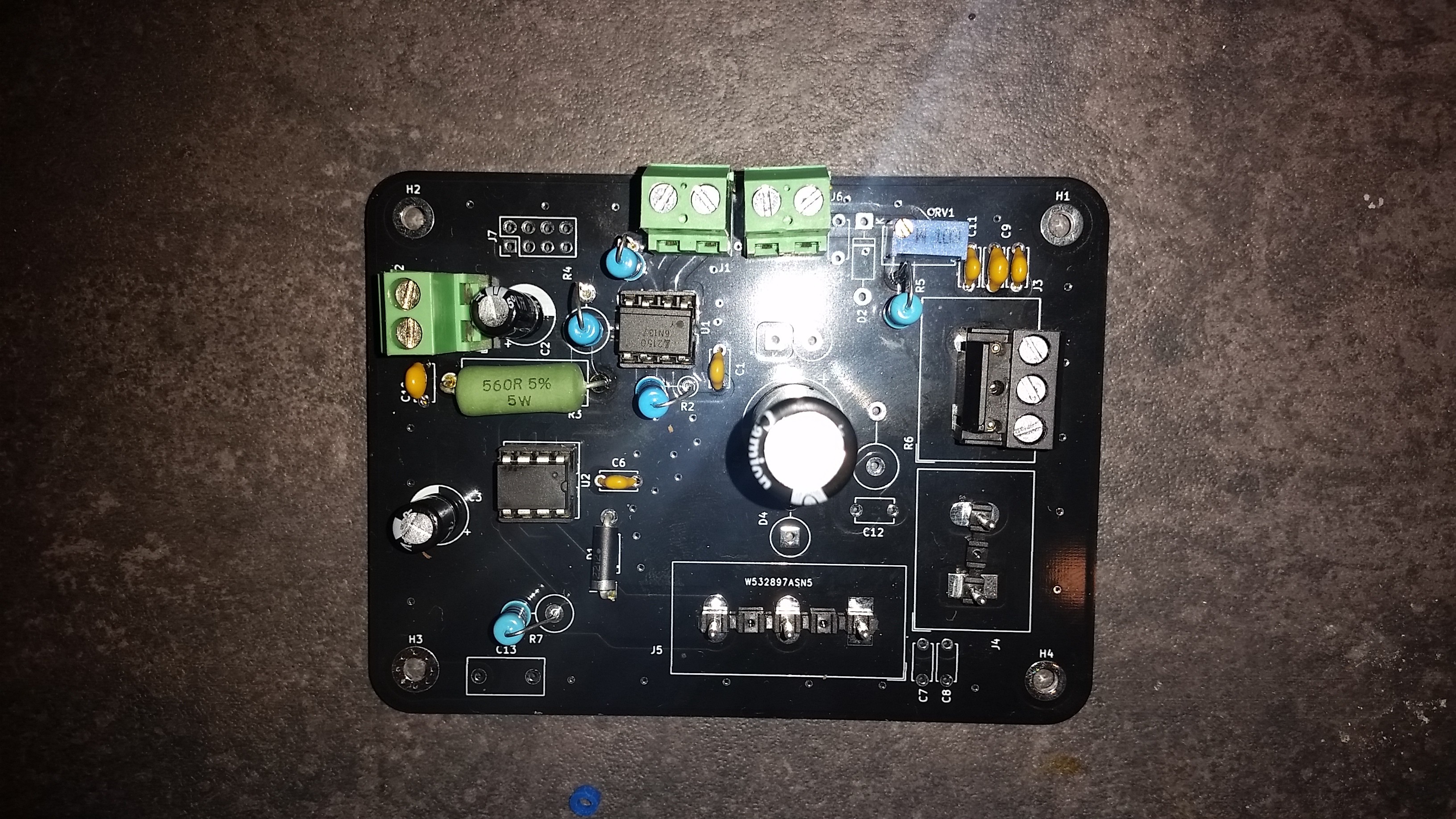
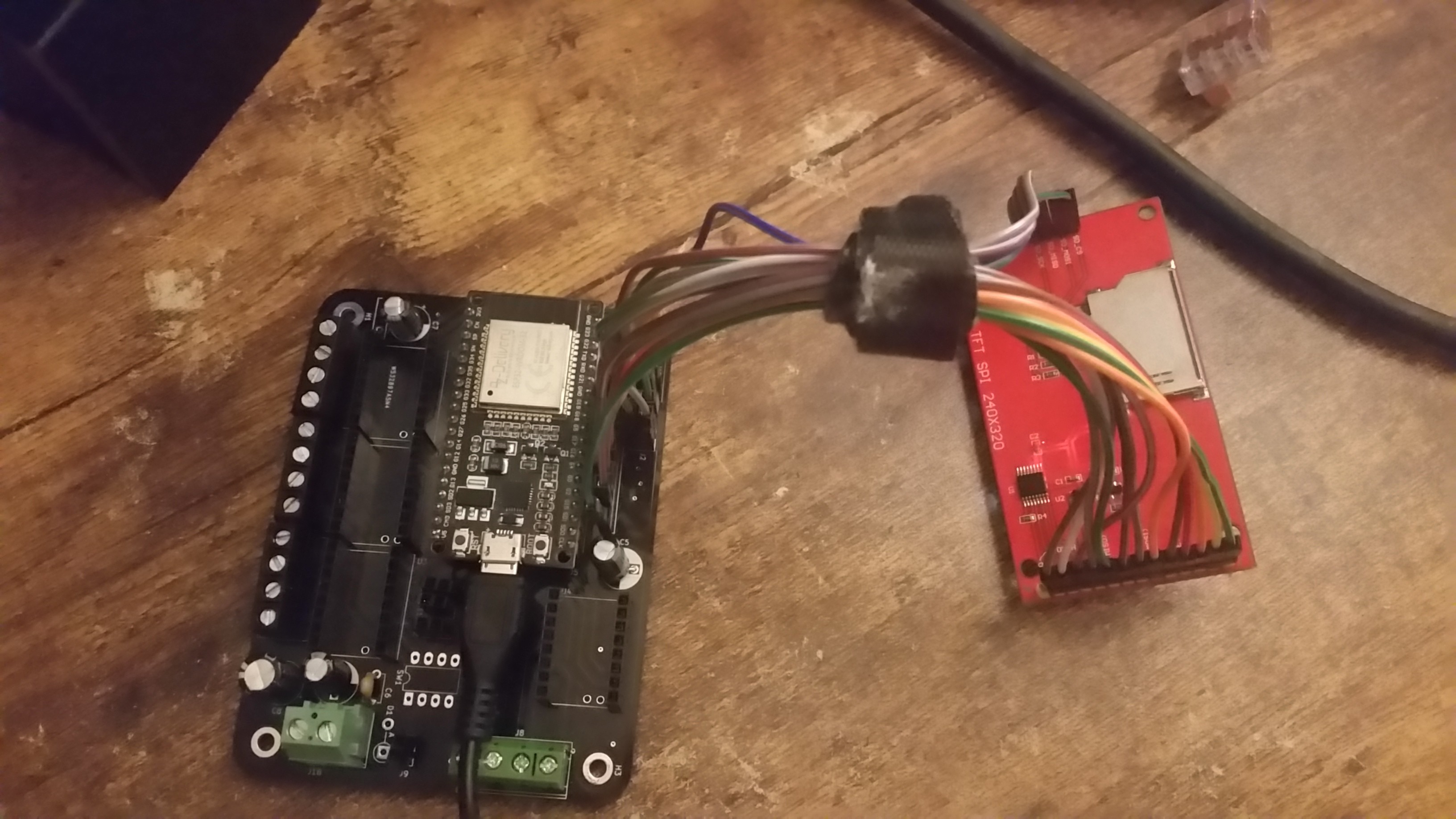
A tiny board that uses an opto-isolated gate driver to switch external mosfets:

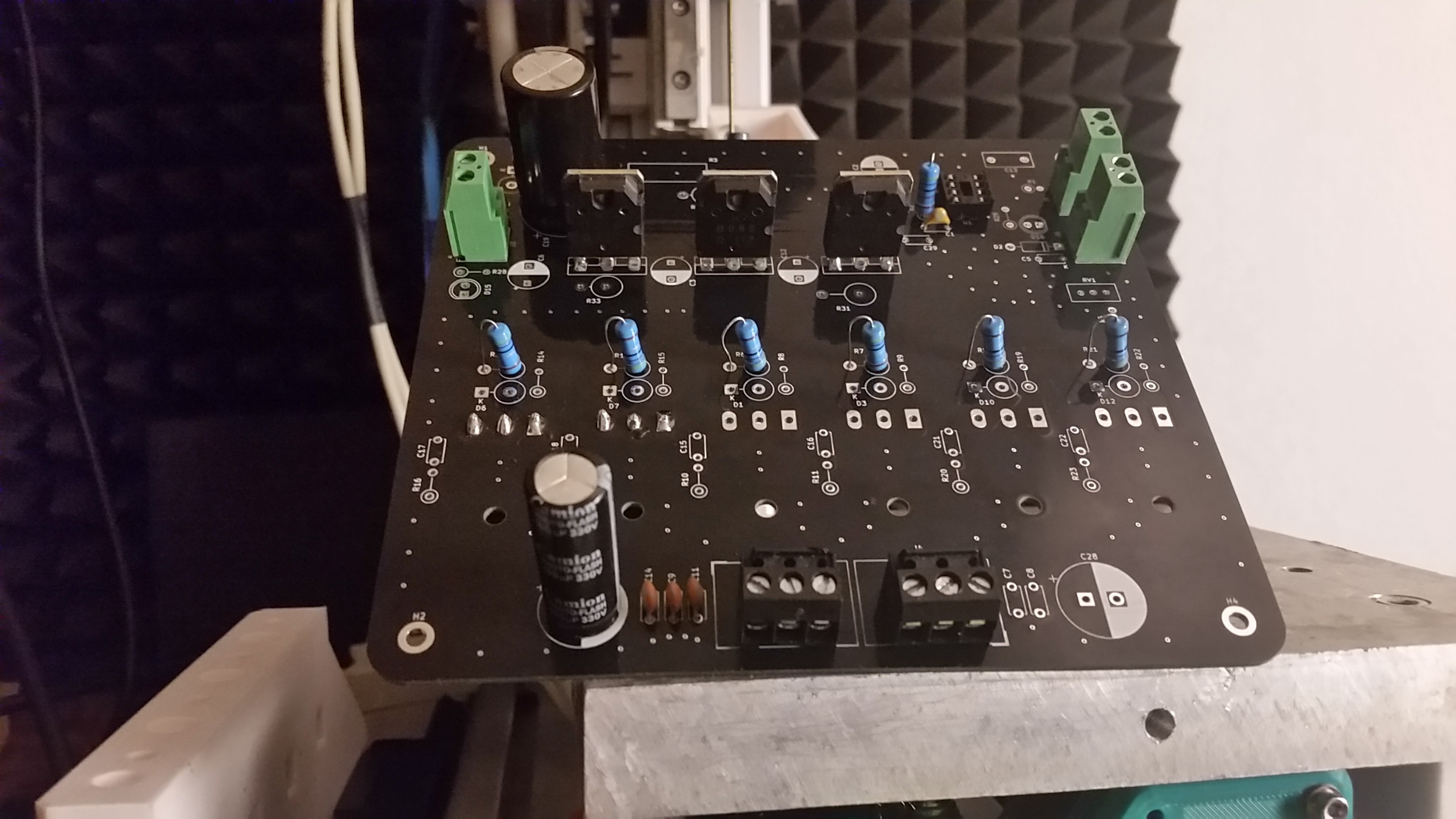
And a big board with up to 6 integrated Mosfets and a discrete gate driver circuit and two shiny indicator LEDs:

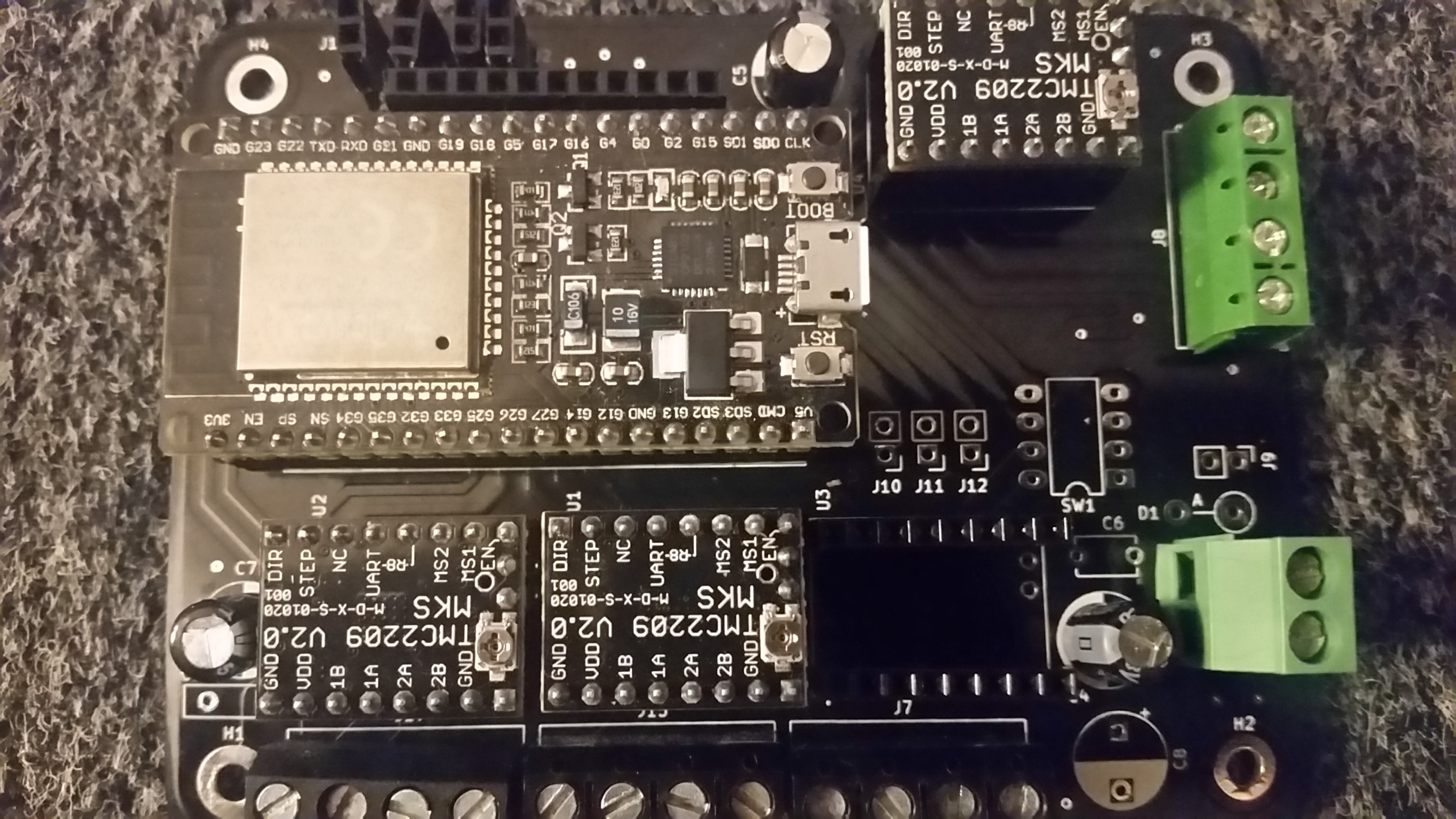
And of course the heart of it all. The ESP motion controller that controls up to 4 TMC2209 stepper drivers:


  • Wire extension and spool holder (images only)

    gedm-dev5 days ago 0 comments

  • New toolhead and the printed wire EDM extension

    gedm-dev09/13/2023 at 13:44 0 comments

    Days have passed. Parts where printing and the HGR15 rail came today.

    The new toolhead is a major improvement compared to the old one that used a weak MGN12 rail. Pretty solid.

    Instead of a cheap DIY drillchuck it now uses an ER11 C12 shaft with dual bearings. One bearing in the top lid and one in the main body.

    The belt tensioner is just another nice improvement.


  • Wire EDM extension for the G-EDM

    gedm-dev09/05/2023 at 21:51 0 comments

    Still not fully finished but it's starting to get somewhere.

  • [Spoiler] Wire EDM coming soon

    gedm-dev09/04/2023 at 12:58 0 comments

  • Cutting a letter into 6mm aluminum

    gedm-dev09/01/2023 at 23:25 0 comments

  • Real negative feed with G-RBL? Yes.

    gedm-dev08/24/2023 at 00:09 0 comments

    Had some tough days figuring out the best concept for XY retractions.

    I first tried a parallel ringbuffer with pure step and dir bits. Wasn't to happy with it and changed it to a position ringbuffer. But it was still not fully integrated.

    Changed it again and now it is a pure ringbuffer that takes position instructions and syncs the position.

    The motion can run up and down the  positions stored in the history buffer.

    Homing works and the GCode simulation runs the G Logo file too.

    The "G" created about 250 Lines. The history buffer is set to 1024 lines but this could be increased to for example 4096.

    Lots of room for some tiny retractions.

    In this video I jogged XYZ and then just let the history buffer walk back and forth.

  • Another deep software change

    gedm-dev08/19/2023 at 11:28 0 comments

    While doing the first 2D test cuts it was clear that I want to be able to change some process parameters in real-time and also be able to reprobe the top surface to compensate toolwear.

    In the past the display just froze while processing. Accessing the SPI display is a heavy CPU load and created jerky motions in the steppers due to the delay it created. This problem was fixed after the full display code went on core 0.

    But It still wasn't possible to do real-time adjustments. This has now changed.

    A process overlay screen was added that allows to change different parameters like frequency and duty and also offers the possibility to pause/resume the process and reprobe the workpiece. It also shows the position of the machine in MPos and WPos.

    The reprobing routine is not finished yet. It already stops the motion and moves to the reprobe position but the final reprobing and resetting of the work coordinate system has yet to be done.

    The reprobe position can be set manually after jogging the machine to the wanted position and set this current position as reprobe point in absolute MPos or just let it default to 0,0 in G54 WPos.

    All settings now show a little infotext that may help new users to better understand what they are going to change.

    The wire extension starts to take some shape too. Far from ready but it should not take too long:

  • Will there be a wire extension for the G-EDM?

    gedm-dev08/14/2023 at 23:37 0 comments

    Some asked me if there will be a wire EDM extension. Of course there will be a wire extension.

    The Code for Wire EDM is already written but untested.

    Took some copper wire and tested it. Axis is reacting nothing burns down or melts.

  • G-EDM vs HSS

    gedm-dev08/13/2023 at 20:14 0 comments

    Mild steel is fun, but HSS means business.

    The settings used where too weak for HSS and I stopped the process. It would have taken too long and currently it is not possible to change the settings at realtime except for the Amps on the PSU.

    Next time I will use a little more aggressive settings. But damn nice.

    The GCode was created with the customized FreeCAD GRBL post processor.

  • GCode, Freecad, LaserGRBL, LaserWeb

    gedm-dev08/11/2023 at 02:05 0 comments

    Ok. X and Y is working. That is a good thing. But the GCode created for Lasers with a bigger laserdot diameter to simulate the electrodes can turn out very ugly.

    A laser moves from on side to the other and doesn't care about overshooting the contours. Normally the dot of a laser is small so this isn't a problem. But a 1.5mm "dot" can create an ugly outer shape.

    I'm currently modifying the internal GRBL postprocessor that is part of freecad.

    First goal is to get electrode up/down movements working instead of using Z axis motions. This could be done within the G-EDM software too but to keep it simple and clean a modified postprocessor would be a good way.

    Generating GCode with freecad is not as hard as it looks.

    Update: Looks like it is possible with GRBL-Plotter to compensate the tool diameter and prevent ugly contours with negative toll diameter values and the output of the customized FreeCAD postprocessor looks promising too:

View all 38 project logs

Enjoy this project?

Share

Discussions

Piotr wrote 08/10/2023 at 00:00 point

How feedback circuit looks like? I want to build similar machine and have problem in this part.

  Are you sure? yes | no

gedm-dev wrote 08/10/2023 at 01:31 point

The feedback is just a voltage divider. that outputs between 0 and 2.8v depending on the voltage drop created. Everything else happens at software level.

  Are you sure? yes | no

joram wrote 07/12/2023 at 08:48 point

This looks interesting. Is the esp32 code already in a sharable state?

  Are you sure? yes | no

gedm-dev wrote 07/12/2023 at 12:49 point

Almost. I just need to confirm that the Y axis works too. Currently building the axis. Should be ready soon.

  Are you sure? yes | no

Similar Projects

Does this project spark your interest?

Become a member to follow this project and never miss any updates