 Stephen Craver
Before we delve into the details of the Smart Recliner add-on, I want to address the construction and appearance of the device. As someone who has been battling MS for over 35 years, I understand that my fine motor skills might not be at their best due to being one-handed. This has led to some challenges in creating a perfect-looking device. I sincerely apologize for any imperfections in the construction. I hope you can forgive this aspect and focus on the potential impact and benefits of the Smart Recliner add-on. After all, it's the functionality and convenience that truly matter.
Who knows, maybe a couple of rainbow or unicorn stickers on it might make it pretty??
The Smart Recliner add-on is specifically designed to enhance the lives of individuals with limited mobility, like me, who find it challenging to operate powered recliners with conventional controls. By introducing innovative automation, this device ensures that reclining becomes effortless and accessible for everyone.
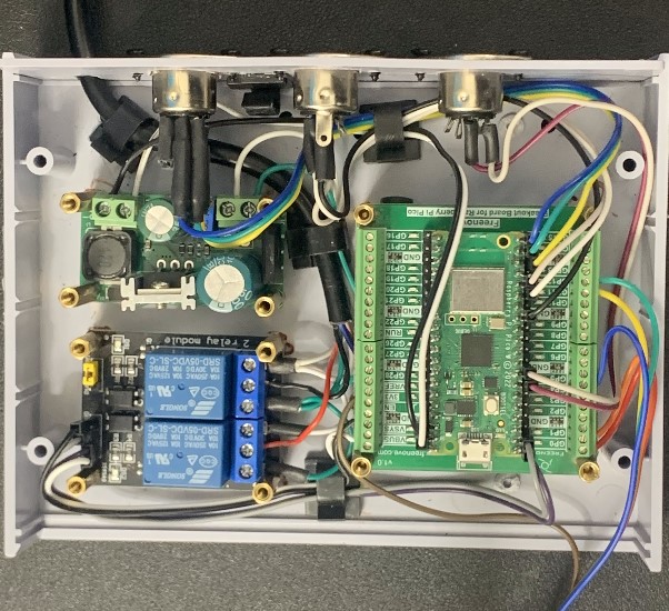
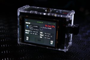
6/15 UPDATE: The project is now in the 'prototype' stage. The first, 'sloppy' concept stage mentioned above, has given way to a much more 'professional' look.
At least I hope so.
My background consists of being an FM radio broadcast engineer for nearly 15 years, eventually jumping ship and landing as a professional software (c#) engineer for the past 20+ years.
CONTRIBUTORS WELCOMED
I have no schematic or code reviewers, but I really could use another set of eyes on this. Also, although the device has Wi-Fi connectivity, I could really use help accessing PICO's file system remotely (Telnet, SSH). HELP!
The device:
Introducing the Smart Recliner add-on - Elevating Comfort and Convenience to New Heights!
Overview:
The Smart Recliner add-on is a revolutionary device designed to enhance the experience of using powered recliners, particularly for individuals with limited mobility. It introduces a level of automation to the chair, bed, or other purposes, revolutionizing the way you interact with your recliner. This device is independent, yet seamlessly integrates with your existing recliner controller, making the transition smooth and user-friendly.
Key Features:
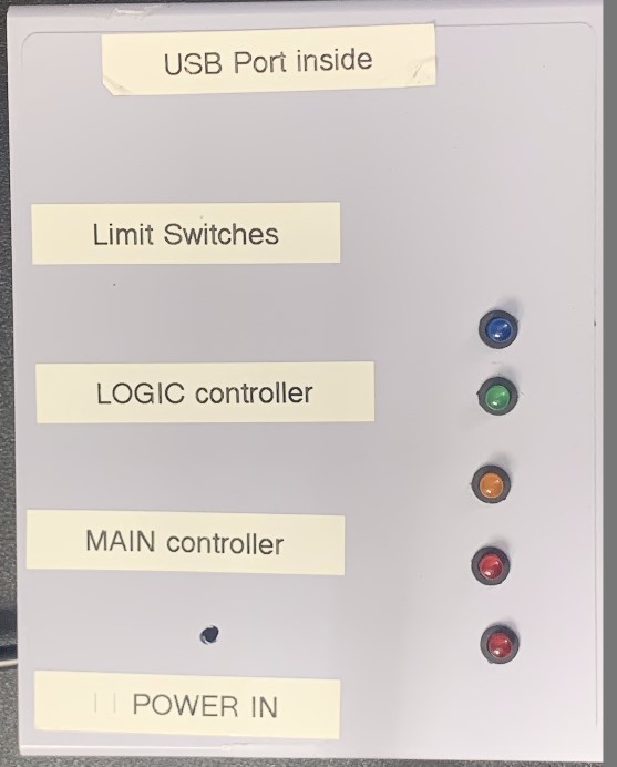
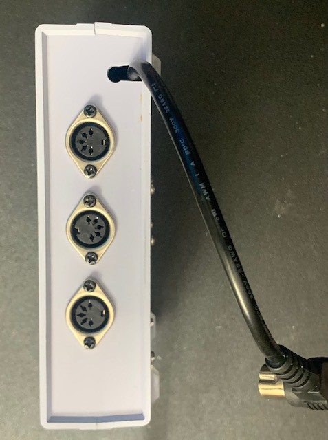
- Dual Controllers: The Smart Recliner can use two controllers: the Main Controller and the Logic Controller. The Main Controller is your existing recliner controller, fully operational and transparent under the Smart Recliner's control. The Logic Controller, which can be a 2 or 4-button model, serves as the automation hub, enabling a whole new level of convenience.
- Home Position Recognition: The Smart Recliner "knows" the chair's position (assuming it started in the upright "normal" position) by counting the duration the motor is engaged. "Up" button reduces the time, while "Down" button adds to it. Additionally, optional limit switches (e.g., "riseHome" and "reclHome") help identify the "normal" position, resetting the time to zero when activated.
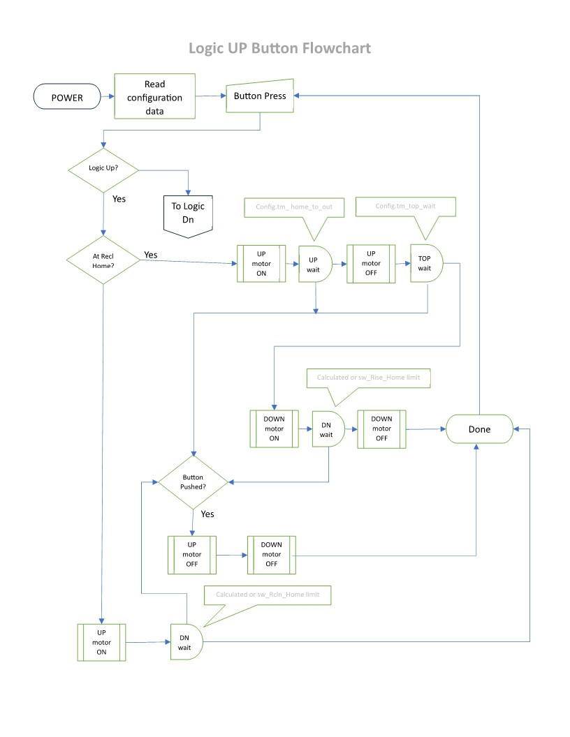
- Automated "Up and Out" Process: Pressing the "Up" button on the Logic Controller initiates the "up and out" process. If the chair is in the "normal" position or has a duration time of 0, the chair's motor engages to lift the chair for an adjustable period. It then pauses at the top for 10 seconds, allowing time to exit comfortably. Afterward, it automatically activates the motor in the "down" direction for an adjustable time, seamlessly returning the chair to the "normal" position.
- Smooth "Down" Functionality: When the chair is in the "normal" position or has a duration time greater than 0, pressing the "Down" button on the Logic Controller initiates the automated "down" process, lowering the chair in 10-second increments for optimal control.
- Optional Limit Switches: The Smart Recliner can...


 Arcadia Labs
 Supplyframe DesignLab
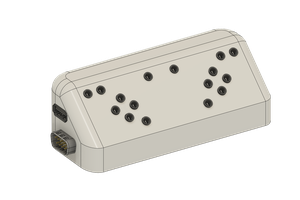
 Julien OUDIN
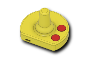
UPDATE: I unintentionally lied. I have business that will keep me from posting videos for a couple of weeks. Apologies!!