 JP Gleyzes
This weather station was part of the Rezodo project. It has been moved to its own project as the Rezodo project was becoming too big to be easily readable !
This weather station is intended to be easily "tunable" to your own needs :
- transmission to the base can be done
- directly by the station itself if Wifi is available
- via Lora point to point to get a much greater range (currently working with more than 2.5 km between base and station)
- sensors can be choosen among the list and two major versions do exist
- wind only (+ sensors)
- wind + rain (+sensors)
The design of the two main versions is basically the same but the "mechanical" parts, of course, differ. We will cover the two versions.
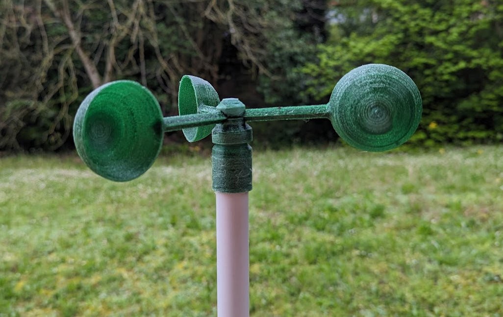
"Wind only" weather station
As I do belong to a RC flying club, we need to know the wind conditions at the airfield. These conditions are locally changing quite fast and weather forecast is not accurate enough for our hobby !
So I decided to design a "Wind only" version of the weather station.
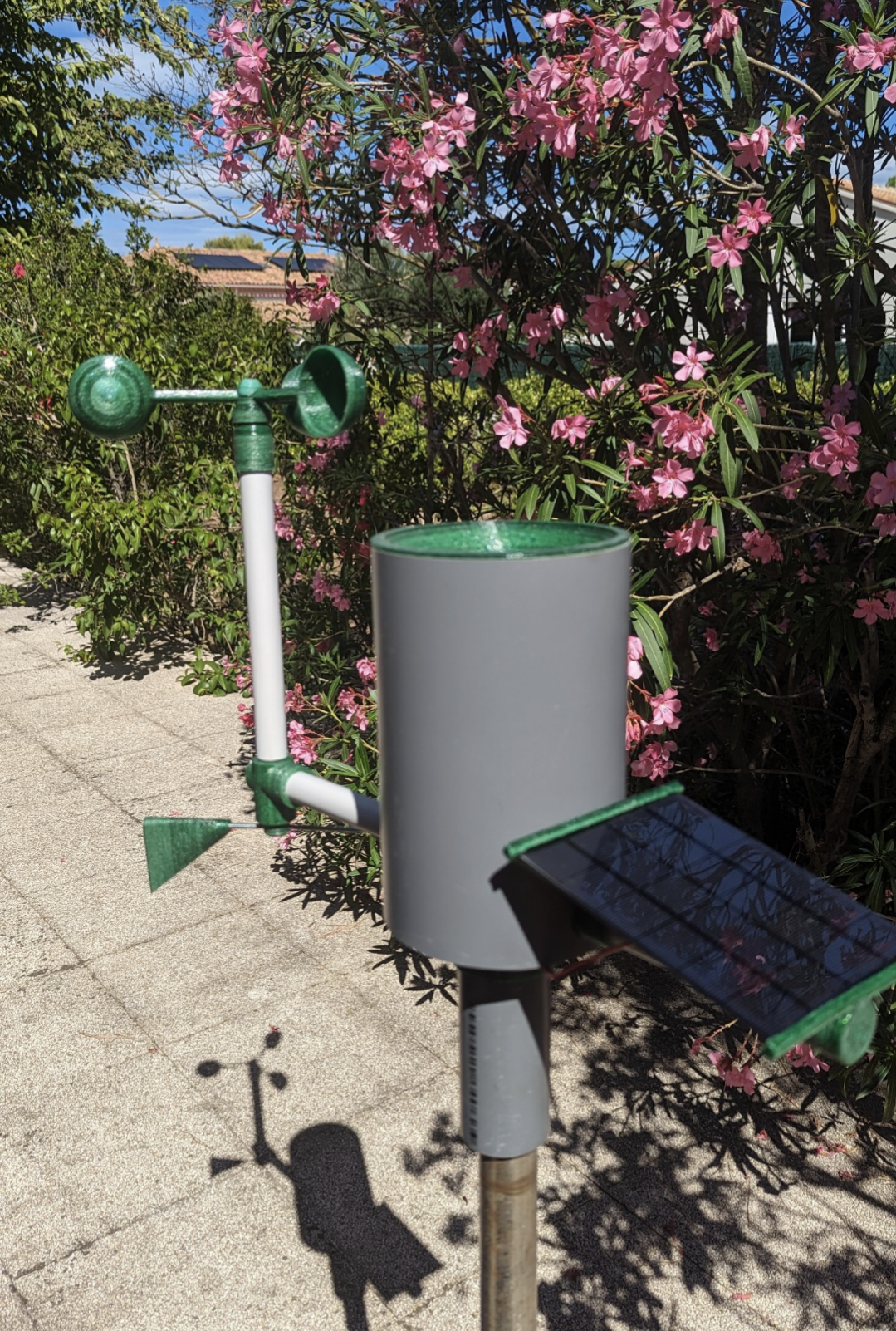
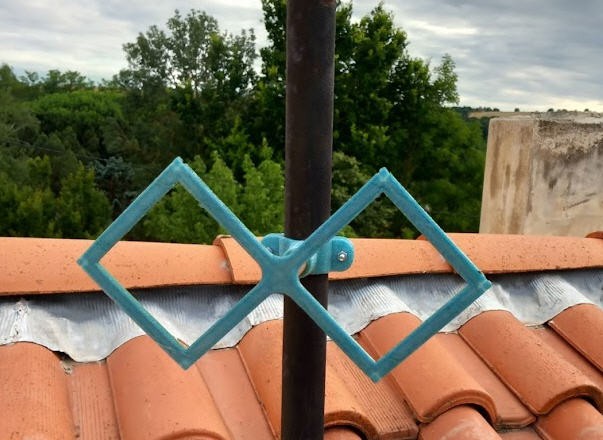
Here it is, installed at our airfield
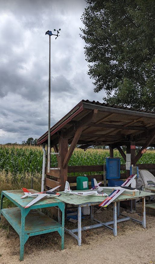
The airfield is far away from electricity network and at 2.5km from the first building where we have installed the Lora receiver.
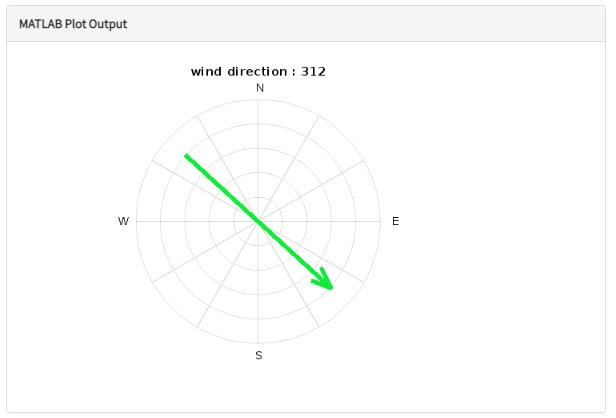
Everything is working now and we have a public access to these nice gauges!
Building this station is not complex. Read all this description and the logs and you will be able to build yours !
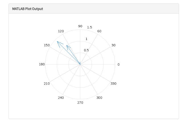
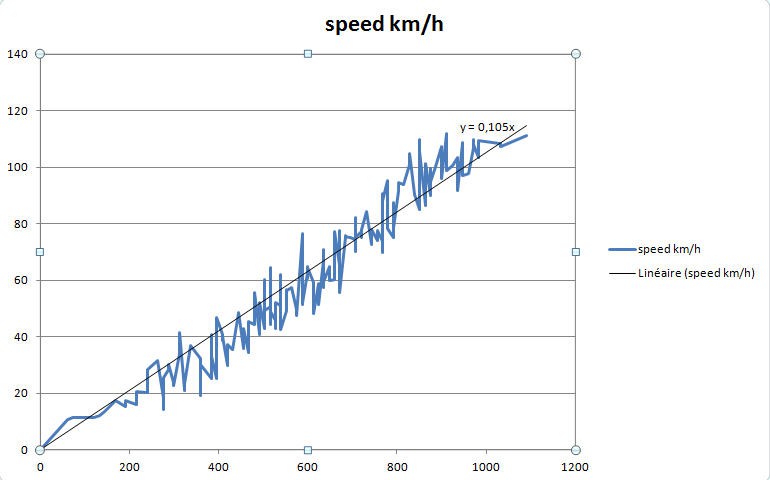
As you can see the wind sensors do work in very low wind conditions.
Price for this "Wind Only" weather Station including both emitter and receiver boards (GTW0 + GTW1) is less than 50€. Bill of Material is accessible here
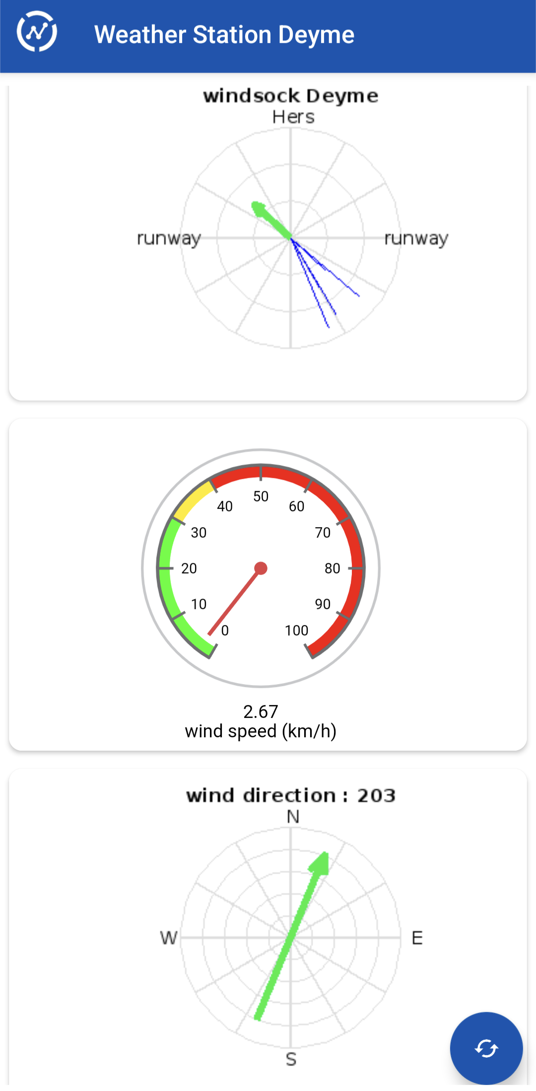
Full weather station
This one is the most complete version, including all the sensors. It mainly differs from the previous one by the addition of a rain gauge.
The electronics goes inside the bottom box, wires go to the sensors into the pipes. PCB is protected against rain.
Here is a picture showing "exploded" view of the weather station:
And here it is during tests:
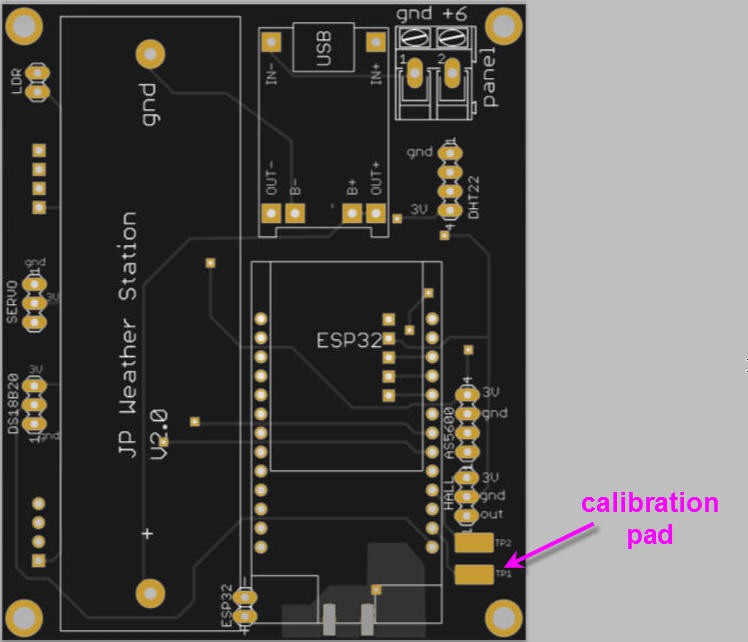
Weather station electronics
This schematics summarizes the electronics embedded into the weather station. The same PCB is used for the various versions of the weather station, and even for the Lora gateway 0 (the one simply equiped with Lora + wifi access + mains power supply).
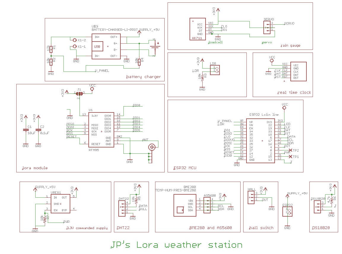
In a few words, it has the following components:
- a lora module for long range communication between Gateway 0 and Gateway 1
- an ESP32 MCU + ESPNow (to be connected to Rezodo FDRS network if needed)
- a rain gauge equiped with weighing sensor for accurate measurement
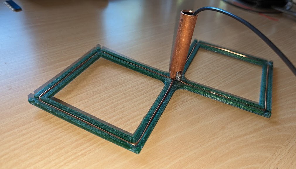
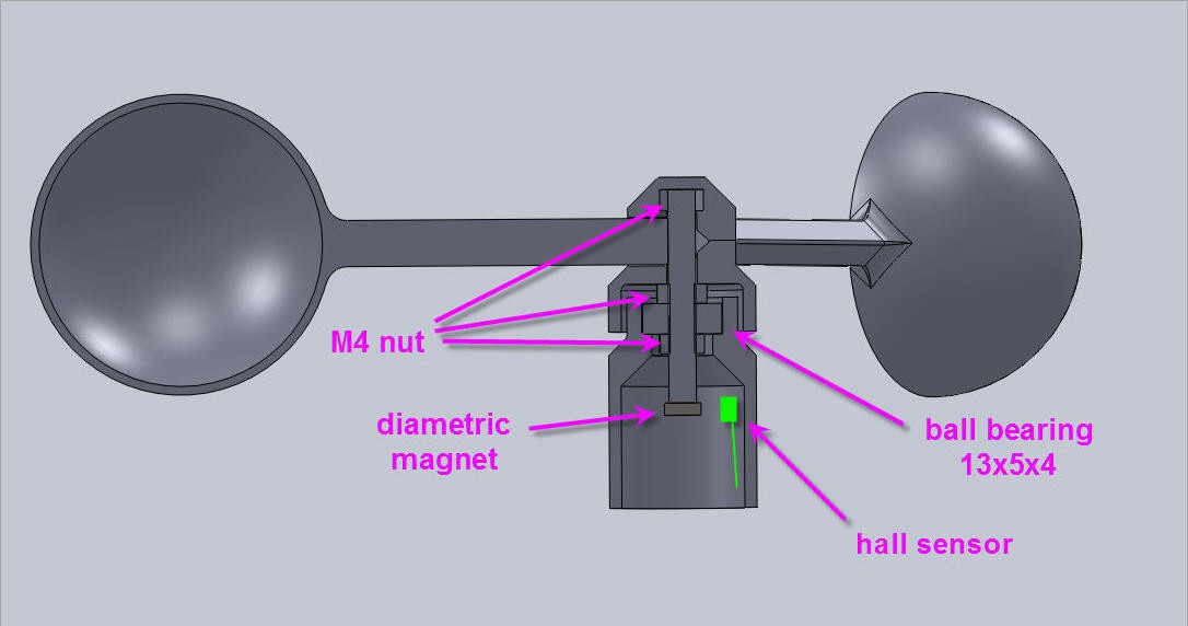
- a wind direction sensor with a Hall encoder delivering 4096 angular postions (contactless... no wear)
- a wind anemometer with hall effect sensor (contactless... no wear)
- temperature, humidity, pressure, light sensors
More details into this log please read it as it contains important informations.
Components + mechanical parts for this schematics should cost around 65€. This price is for the "full" Lora weather station and does include the Lora GTW0 and GTW1...
To build the weather station you will have to add a few 3d printed mechanical components.
All the 3d printed parts are available on thingiverse (links on the left of the main page of this project).
I printed them with plastic bottle PET filament. See here : Pullstruder project on hackaday.
Never print these parts with PLA... They will melt under the sun. Choose PETG or ABS or PET.
PCB
The PCB have been sponsored by PCBWay. You can order them here : Weather Station PCB @PCBWay
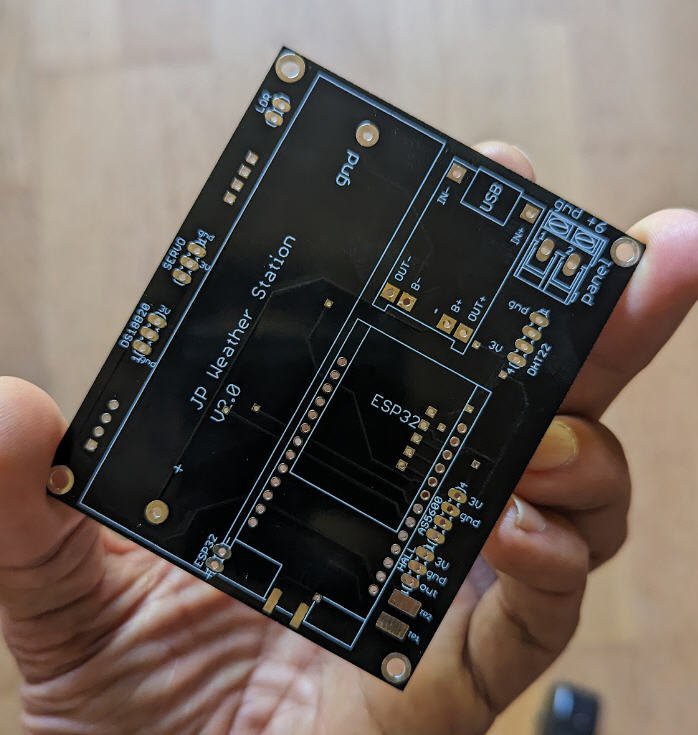
As you can see, this is the V2 version of this board (the latest one).
The rain gauge
There are a few ways to measure rain. The most commun design is "tipping bucket"
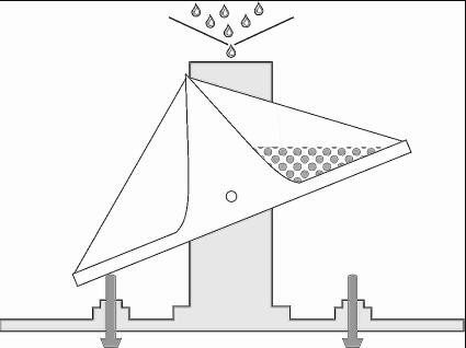
These rain gauges if not "dynamically corrected" may suffer from poor performances. They under estimate high rains and have a poor precision for "small rains". The bucket has to "tip" before counting the water inside...
Please...
Read more »


 Danie Conradie
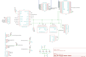
 Nevyn
Nevyn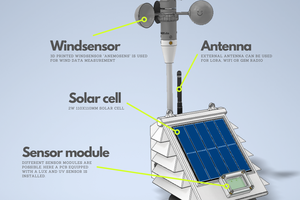
 Fab
Fab
2.5Km.. Cool