 Petar Crnjak
Project log reading order: PAROL6 control board, mechanical design, Software design
Github repo with PAROL6 Files and building instructions: Link
Github repo with PAROL commander GUI: Link
Documentation: Link
Join Discord!
Follow us on Instagram, Youtube, or Twitter!
Problem
I first saw a need for robots such as this in my high school days where 30 students were working on one robot. At colleges, it was nothing better. I did some research and that was the situation in most colleges. My first attempt to change that and make it one robot per student was with Faze4. That project was financed by the college but was not a big hit because of its large size, imprecision, and lack of easy-to-use intuitive software. The second time I saw the need for a robot such as PAROL6 was when working as an RnD engineer on electric vehicles. Building a prototype is one thing but building a production is another much harder thing. I saw many ways robots such as PAROL6 could help companies that need to go from RnD to small production, or at least try to accelerate their RnD processes. Tasks such as adding thru-hole components, placing PCBs to test jigs, handling PCB, gluing, inserting brass bushings, and many more could be in some part automated with robots such as PAROL6.
Solution
Solution
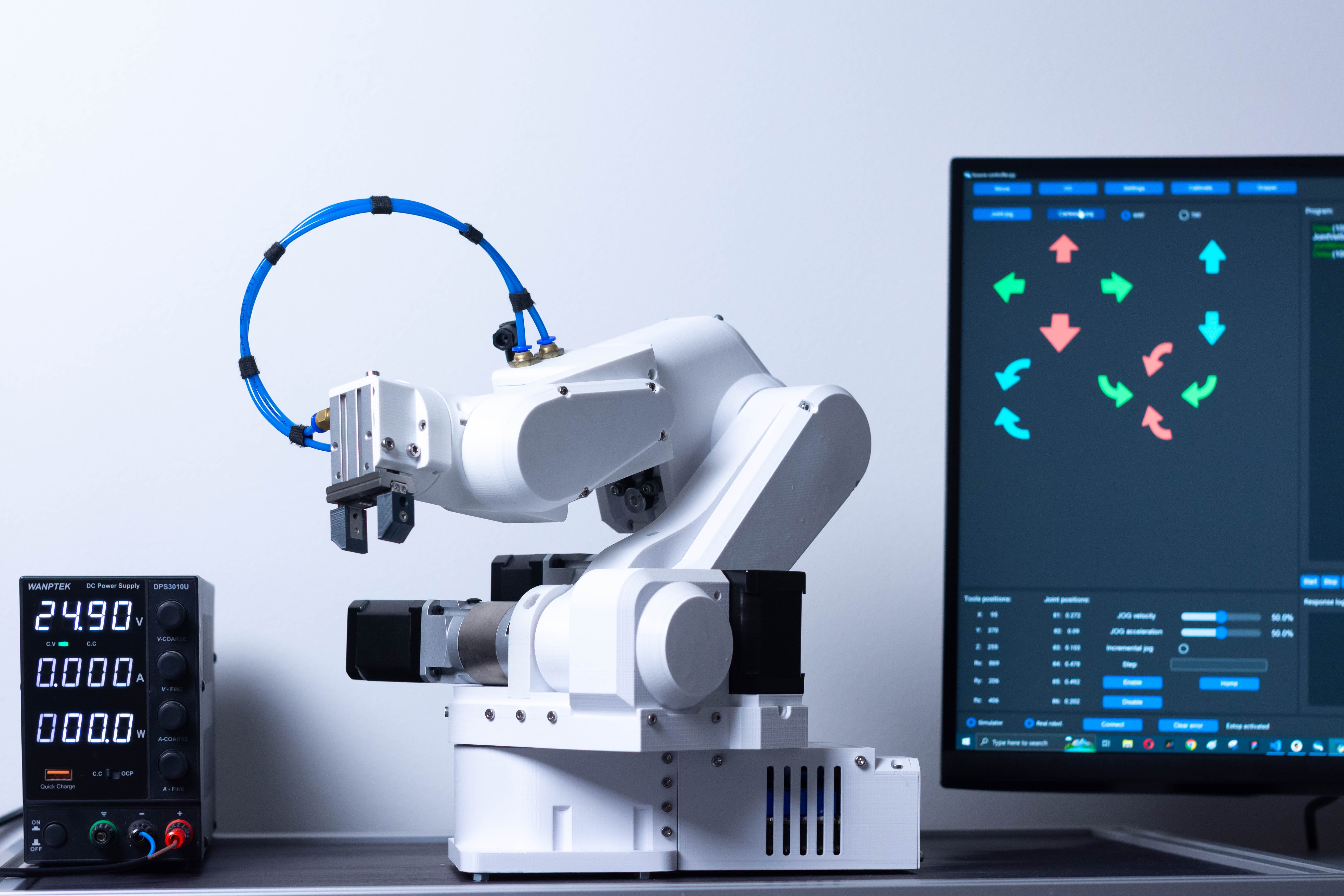
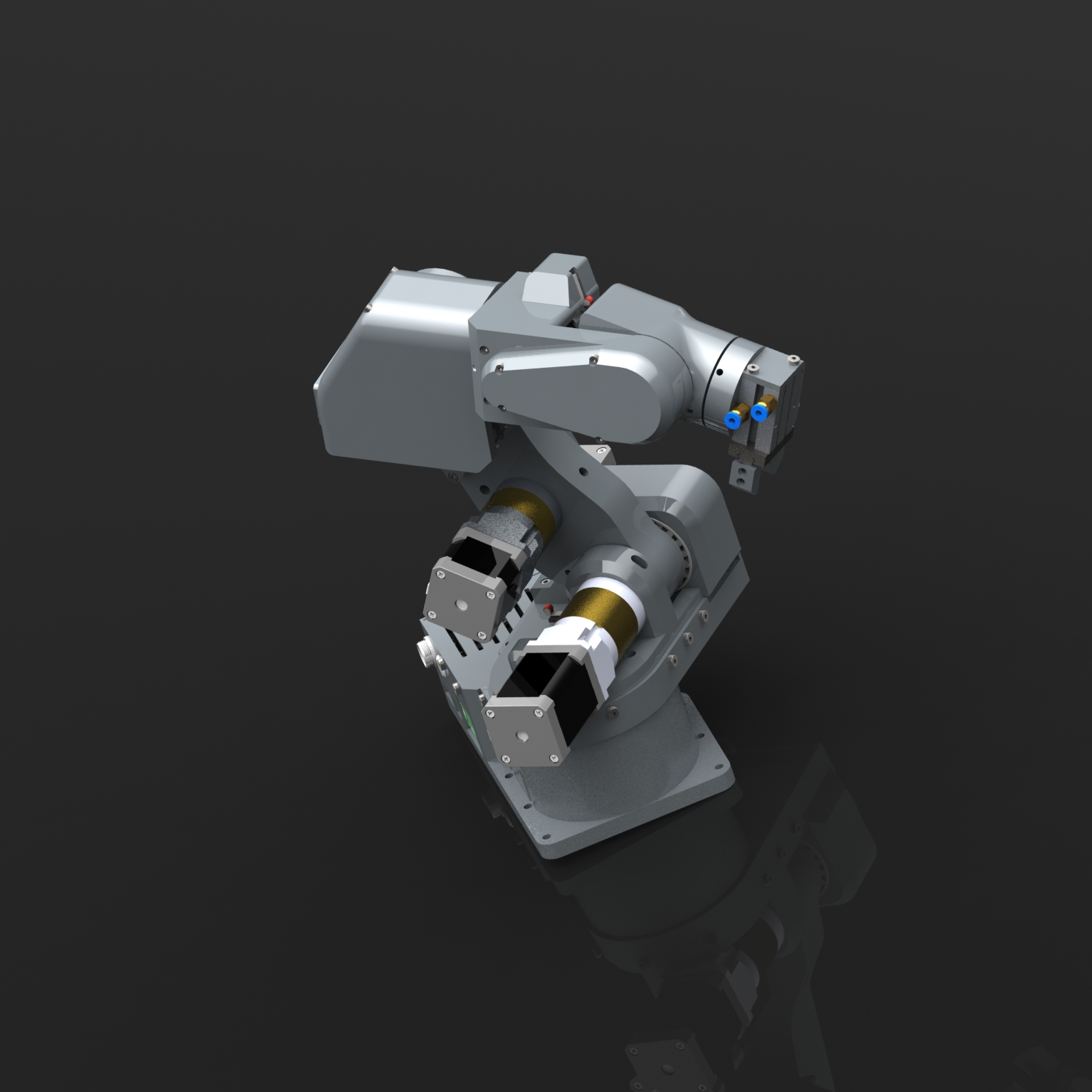
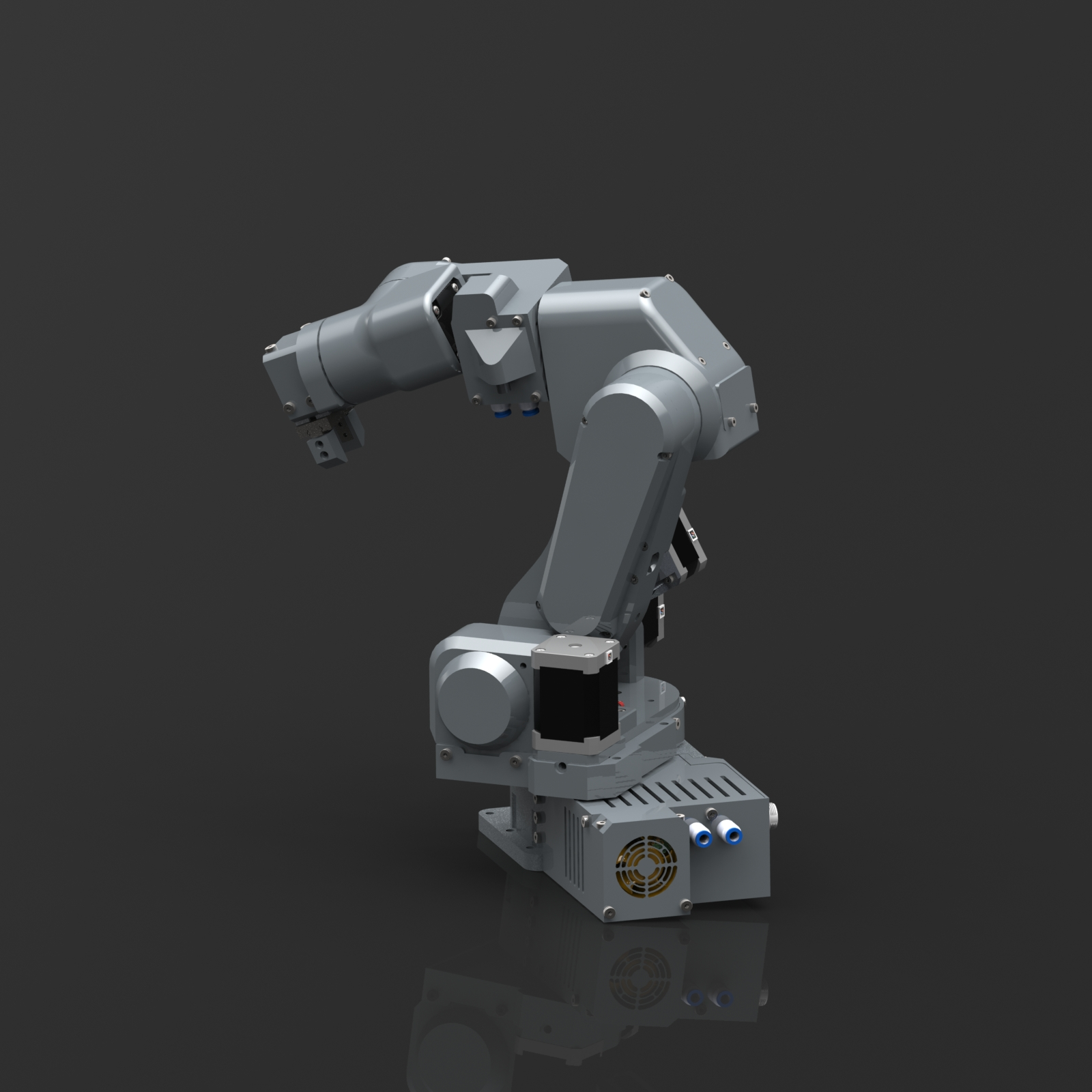
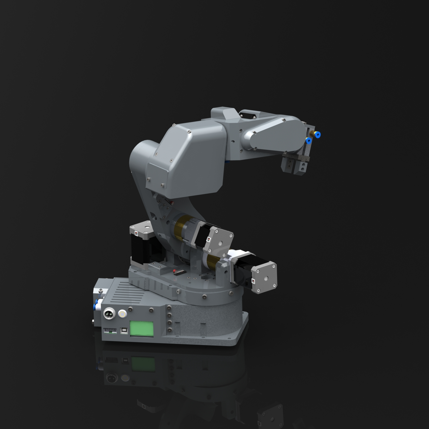
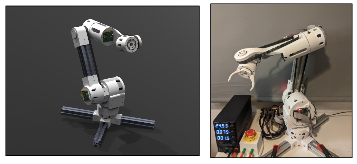
PAROL6 is a desktop robotic arm. Its reach is 400mm and has 6 axes of freedom. Its capabilities are on par with industrial robots in terms of repeatability, speed, and usability. It is equipped with stepper motors and precision planetary reducers/belt drives. Its mechanical parts can be 3D printed on any desktop 3D printer and its full weight is only 5.5 kilograms! In terms of connectivity, it has pneumatic tubes running thru the robot and the ability to connect a force-sensitive gripper that is being developed.
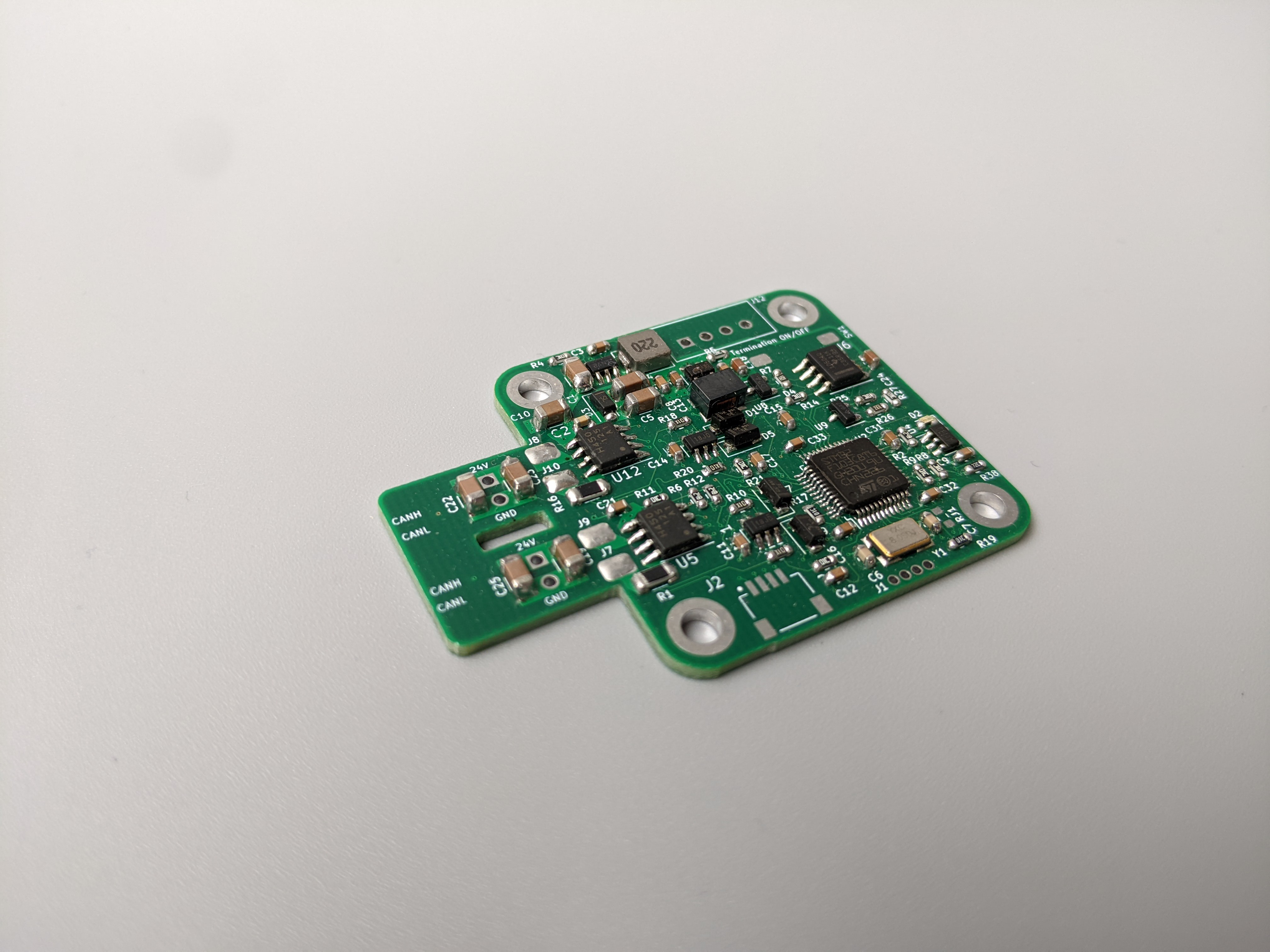
The design is minimalistic and because of that can be easily modified. Stepper drivers can be upgraded to a closed loop for almost all axes without any major design changes. For that purpose closed loop stepper drivers running FOC have been developed.
Previous robots
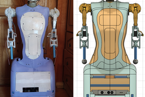
Faze4 - Project link
Faze4 was my bachelor's degree project and was financed by my college with the goal to make a robot arm for education. This is where my realization came that robotic education is very underdeveloped. It is mostly done on simulations or with 10+ students working on one robot. Faze4 was supposed to change that. It is a fully 3D-printed behemoth of a robot with a reach of 580 mm, a weight of 15 kg, and fully 3D printed.

Problems of Faze4 were many:
- Too large a robot for students to manipulate safely
- Printed gearboxes flex and make precision and repeatability terrible
- Underdeveloped electronics and software
- Because of all of the above, it was hard to work on and develop software
Nevertheless, Faze4 is still one of the most popular DIY robotic arms and is being used by multiple collages, as part of masters' and bachelor's theses, and by the maker community in general. Even 2 accelerator stage startups are using Faze4!
CM6 -Project link
CM6 was my master's degree project. It is using gimbal BLDC motors and printed planetary gearboxes paired with custom BLDC drivers called S-drive. This robot was of the experimental type where the goal was to make a robot arm that acts like a human arm (in stiffness, compliance, speed, and payload). It was achieved by using QDD actuators and experimenting with writing motor control software. The results were great and the robot's performance...
Read more »


 Maximiliano Rojas
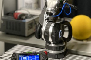
 Adrian Prinz
 therobotstudio
 Peter.li
Hi, I really like the robot you designed .
Do you have the 3D Step files ??
I would appreciate it
Thanks