Close
0%
0%

Minamil 3dp: another minimal CNC mill

A very compact, very inexpensive, very DIYable, very precise little CNC mill. This one uses 3d printed parts.

Public Chat
Similar projects worth following
"MInamil" -- this time it's "Minamil 3dp" because 3d printed -- is a minimal CNC mill that actually works pretty well. It's small and it's not strong, but it's uncommonly precise for an amateur-accessible machine. Small is a feature, and light cuts with small cutters gets stuff done with available strength and stiffness. Work volume 75 mm x 75 mm x 50 mm.

Finalist! Yay!

Finalist in the 2023 Hackaday Prize "Gearing Up" challenge, that is. And again: yay!

Thank you Hackaday Prize judges!

Now onward to get some more done and a lot more writeup in here...


<17 Sep update:

Earlier in this space I whinged:

Ugh. Life interferes with writing. I've been racing to get stuff actually built and working vs. handwaving about what I think might work. Because I need that reality check myself. Hopefully pictures will help show where this project is going. Also check my earlier laser cut mill for an example of yes-really-you-can-build-this documentation that I aim for. And I think this will be a lot easier to build than that one.

Since then I've managed a few more log entries and ... today's increment of progress ...

uploaded some STLs. For the X+Y stage. So if you want to build one of these little machines, here's a chunk to start with!

/update>


Minamil 3dp is another little CNC mill. This one uses 3d printed parts, which give (at least) two advantages:

  • probably more people can 3d print parts today than can laser cut parts
  • much easier assembly vs. building 3d structure from 2d parts

While not at all necessary to make the CNC parts work, a little more work put into the frame/enclosure can make a more practically usable result. The example shown below also shows:

  • a completely new configuration of the integrated enclosure concept relative to earlier work
  • more complete actual accomplished integration of accessory stuff that could be integrated but previously wasn't

And a little side show that makes this work, that I haven't seen elsewhere, and that might help anyone trying to do fine work with a cheap rotary tool: reducing runout.


Cut small stuff from useful materials:

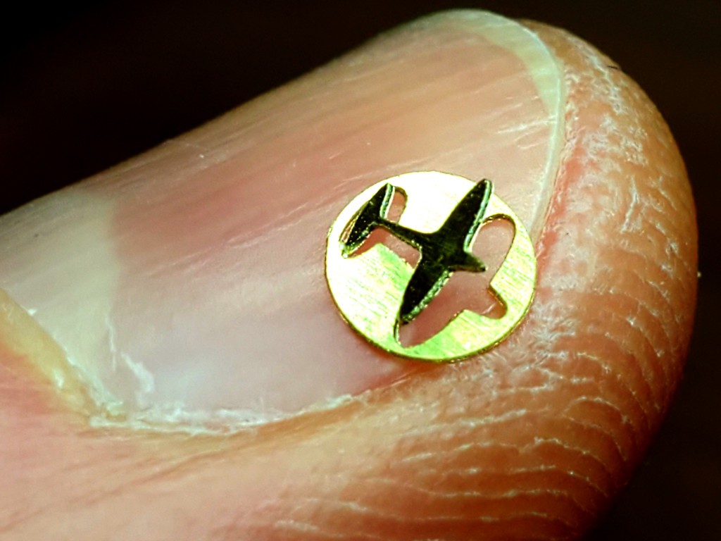
Little airplane in a 4 mm disk cut from brass shim stock with a 0.1 mm V bit.

(yes, I will mix units horribly in this project. it will be ok, we're not trying to land on another planet.)
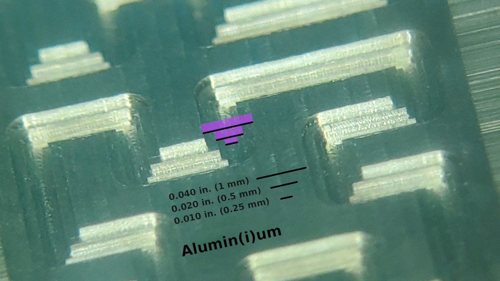

Sharp, accurate features in Aluminum with tiny cutters down to 0.010" (0.25 mm). This pic is a backlash test pattern for the "big" cutter that I repeated with the smaller cutters because new toys.

This short video is kinda neat but doesn't really add much so I'll link instead of embed so hopefully it won't slow down your first scroll through this stuff:


Mill circuit boards for fine-pitch components:
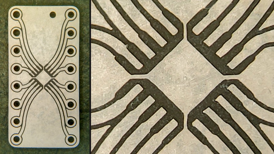
Breakout board for 0.5mm pitch QFN-16. 
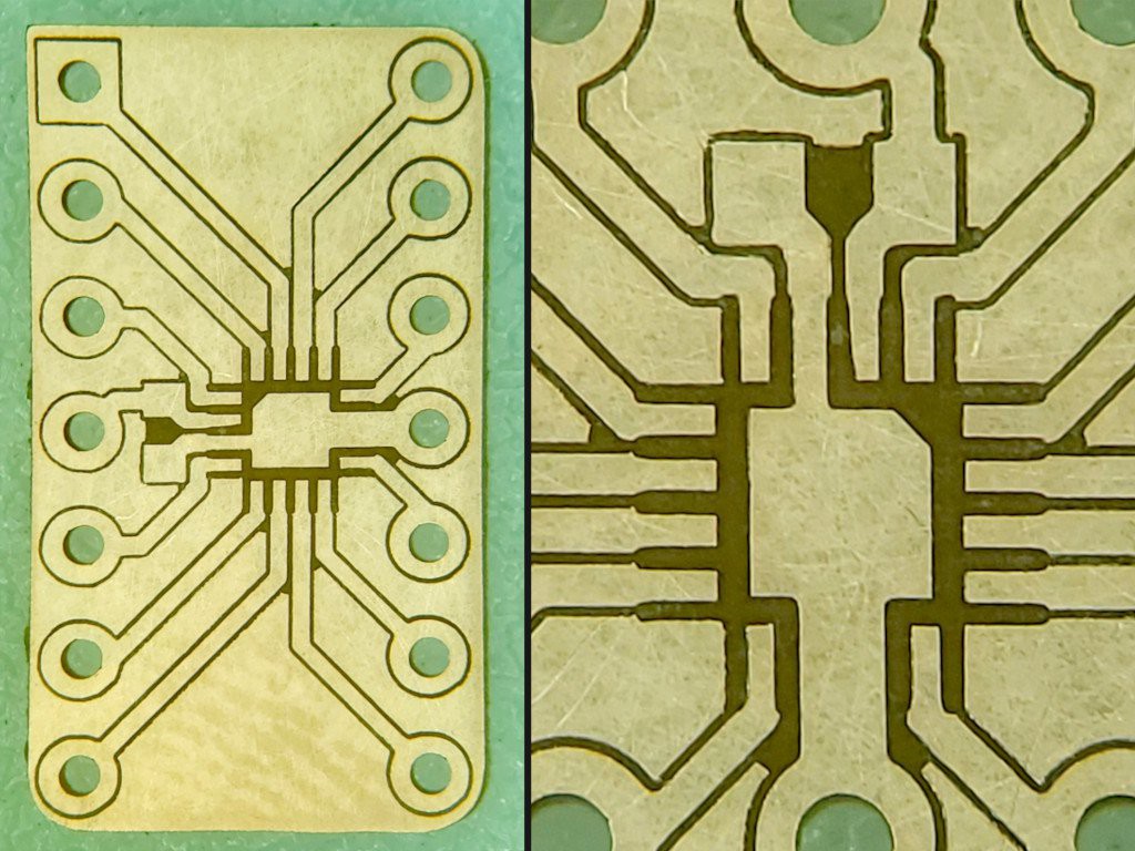
A more specific 0.5 mm pitch QFN-16 breakout for TLV7044 with supply bypass closer to the chip and pinning like the DIP & SO packaged parts. For a different project. Hopefully I'll be able to replace this pic with a populated board "soon"...
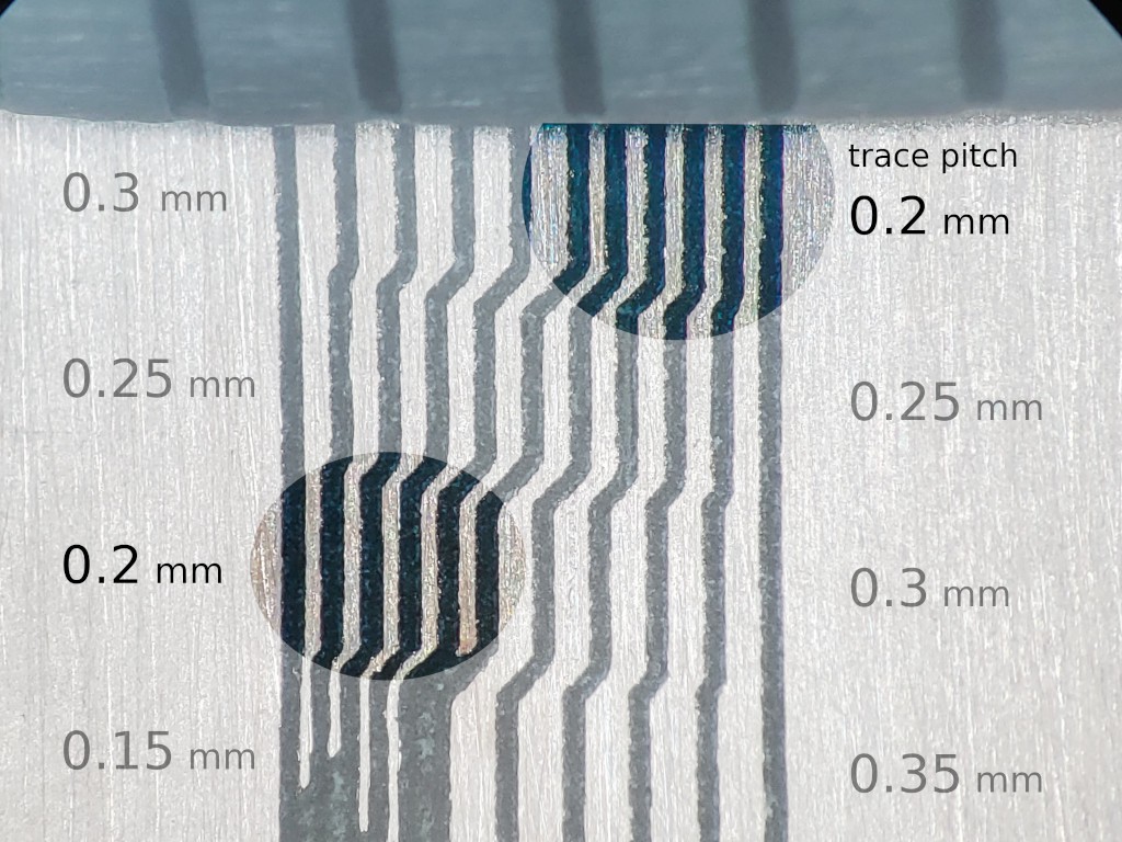
Isolated traces down to 0.2 mm center-center pitch with a 0.1 mm V bit.


But that's all flat stuff :-/

Yeah. I've been working on the tool instead of making stuff. But check this out:

First I'll show this little bevel gear,...
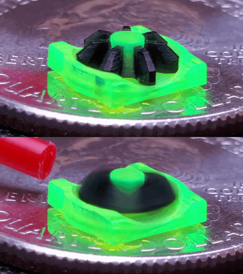
... because the "3dp" 3d printed mill that is the object of this project actually for real cut that gear at MRRF. So I hope you'll accept some parts cut by the earlier laser-cut version of this CNC as an illustration of capability:
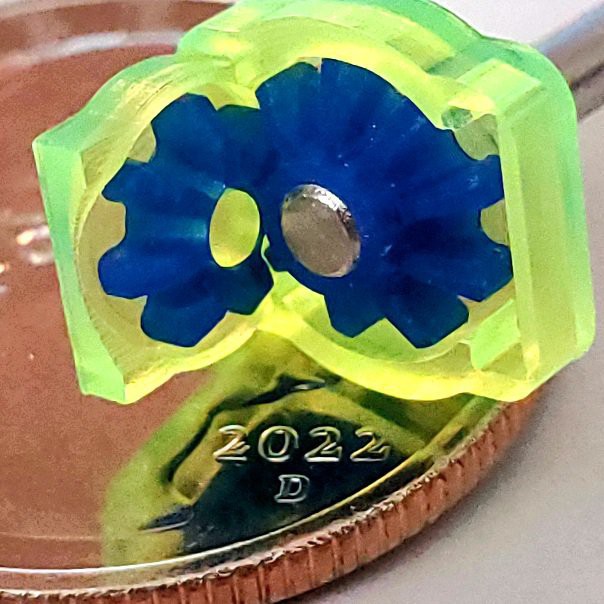
Spider gears and structure parts for a little differential with a US "quarter" coin for scale.
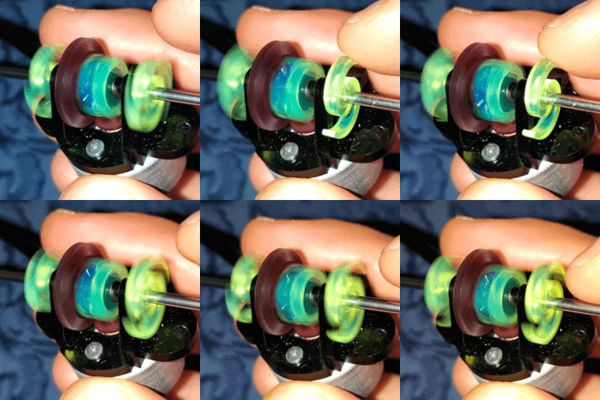
The spider gear assembly in the complete differential is smaller than my fingernail. There's a <4 min. video about that over in the "2dc" project but it's old work and too much about the earlier laser-cut design to include in this project.


Packaging for UX

The CNC mechanics consist of an XY table and a separate Z axis. The two parts need some sort of frame to hold their positions relative to each other. The frame can be very basic. But I want to use my machine in a smallish urban condo with no "shop"-like space.  So I've put a little more effort into the frame and packaging..

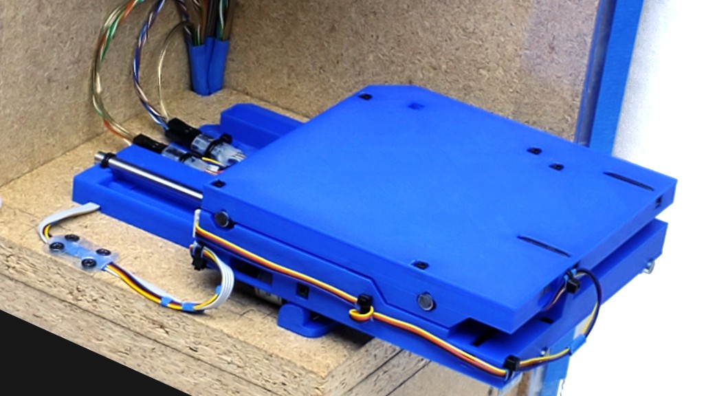
The "telescoping" slide design allows very compact non-operating footprint.
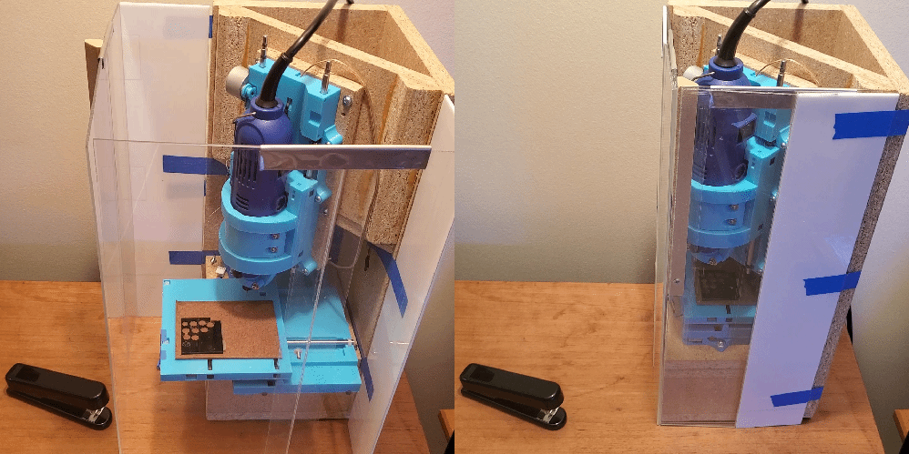
More about packaging -- which is already...

Read more »

minamil3dp-XY-STLs-v0.9.0.zip

X+Y stage parts. For slicing info see https://hackaday.io/project/192074/log/223146/

Zip Archive - 6.69 MB - 09/18/2023 at 02:28

Download

  • XY stage assembly

    Paul McClay3 days ago 0 comments

    This is a draft in progress, but if you want an early start here's something to start with. There is a lot of me describing what I do rather than saying what you should do because this is just the beginning of letting daylight into the path-dependent evolution of how I've been doing this, and of the "this" that I thought I was doing. Some stuff may be mid-edit nonsense. Or pre-proofread nonsense. Public chat is open for the project -- big orange button on the project page.


    Build yer X-Y table/stage/thing


    print

    plastic parts

    part checks & cleanup

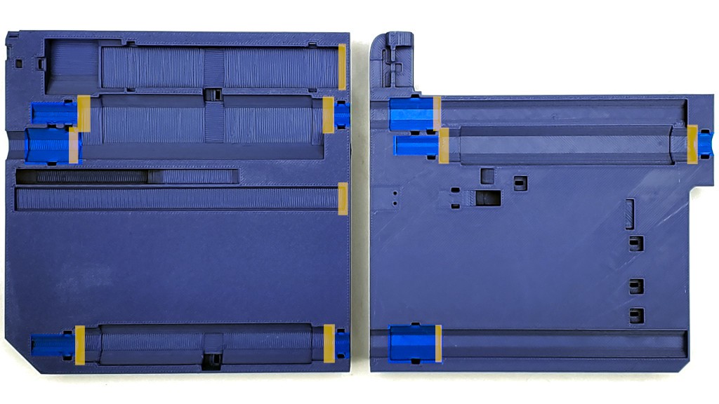
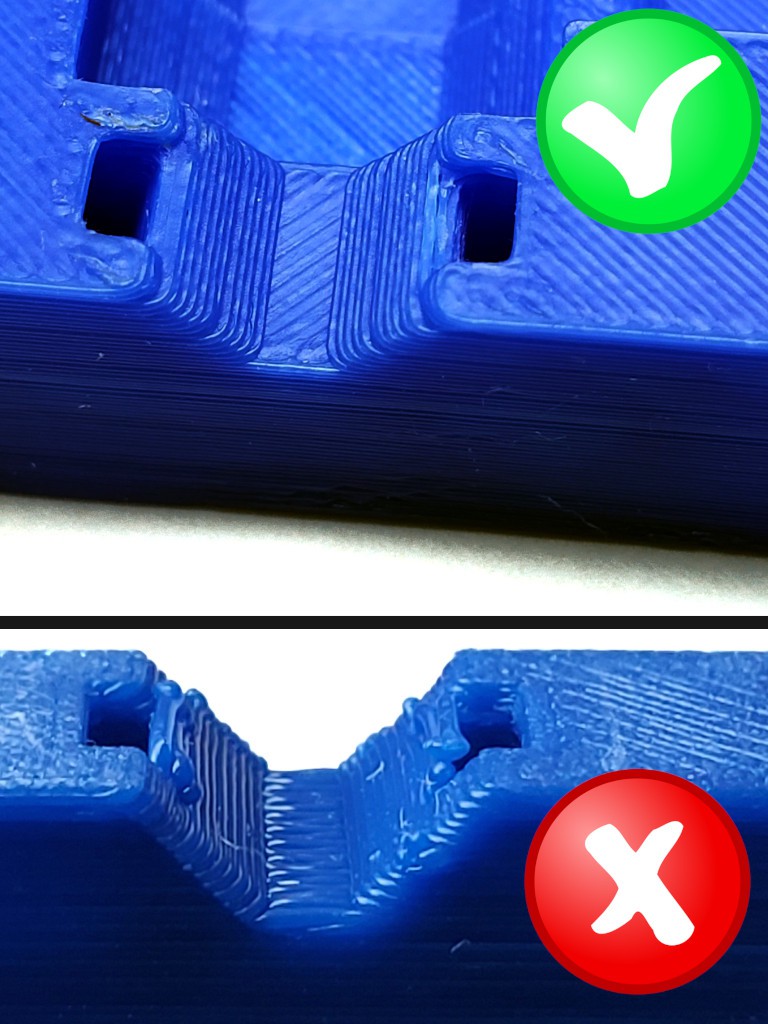
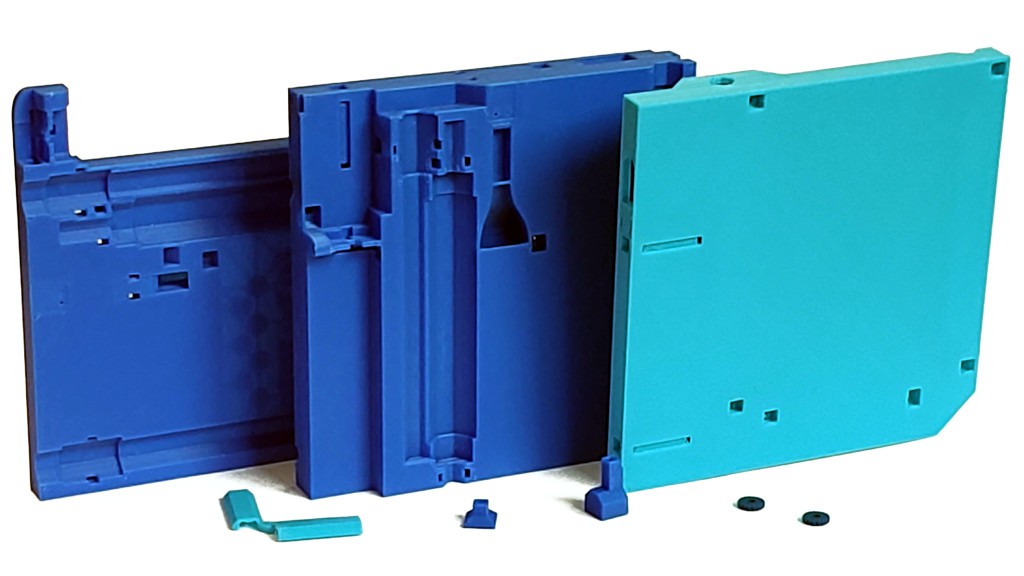
    Check all the V-block surfaces -- the 45º flats within zip tie circuits. See bright blue highlights in the image below. Low spots are probably ok but high spots are trouble.

    Check some of the vertical flat surfaces, and probably trim some edges. See the yellow highlights in the image below. They include the inboard ends of the bearing V-blocks and both ends of bearing clearances. The outboard ends of the bearing V-blocks need to be clean enough to allow the bearings to sit level in the blocks but are not dimensionally relevant.  Also the perimeter end of the motor bay and the business end of the limit switch clearance. These surfaces should be flat and perpendicular to the top or bottom of the part. but likely have some distortion due to elephant's foot, top solid layer expansion or some such, and likely need a little trimming where the vertical meets the top/bottom face of the part.

    note: the bottom part you printed from the STLs here will have three attachment tabs around the edge that are not shown in the photos here (and fewer holes on the bottom)

    "bottom" & bottom of "middle" parts shown -- check same features for "top" and top of "middle" parts
    good V; bad V

    The low locating feature at the other end of the motor bay needs to be clean too, but it always has been in my experience.

    Generally clean up stuff that doesn't look right.

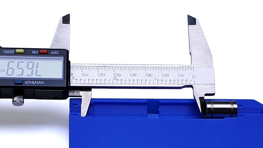
    You can validate bearing clearance cleanup by dropping in a bearing and measuring the remaining clearance. That will be the hard limit to range of motion.

    With geometrically perfect parts, that would be 77.2 mm. If I continue assembly with that part as shown, and if that's the shortest clearance of the three in that axis, I'll end up with 0.6 mm less range of motion than the CAD model. That's still comfortably more than 75 mm, which I think is ok -- 3d printed PLA after all -- and is the reason why I say ">75 mm" instead of "77.2 mm". 

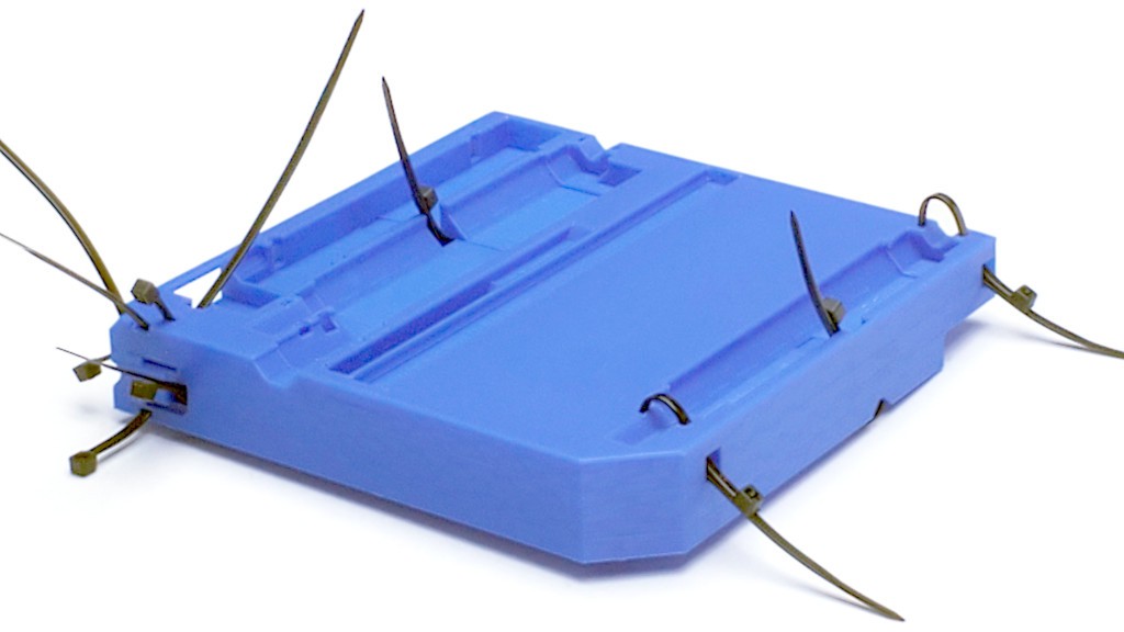
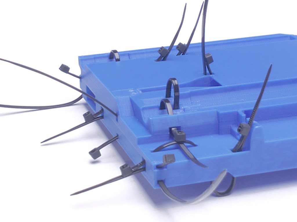
    Check that a zip tie fits through all the tie passages. It may not always be obvious which way a tie is supposed to go, so the next couple of photos try to show orientations for all the ties in the "middle" part.

    zip tie orientations
    porcupine-mode for illustration only -- a single tie will suffice for checking all the passages

    I think that part includes examples of all the ways ties are used in the "top" and "bottom" parts, so you can check those parts too.

    "Elephant's foot" or expanded top solid layers might constrict some of the tie head openings, so check that a tie head fits freely in any that look tight, or trim edges for a free fit if needed. It's unlikely that a head won't fit at all -- that would be really bad layer spread -- but any friction holding the head will make removal a little tedious.

    Where tie heads should not stick up, like on the top surface of the top part, make sure the bottom of the head clearance recess printed cleanly so that the head sits all the way down. Especially where the recess is printed upside down; sometimes a slightly droopy bridge that looks harmless enough will prevent a tie head from sitting below the surrounding surface.

    drill the hole I didn't think of until...

    ...starting this by disassembling the last unit I had put together which was the first with the arch brace under the top. (the unassembled parts I had at MRRF, for whoever might remember that)

    At which point I discovered...

    Read more »

  • Parts to get started

    Paul McClay5 days ago 0 comments

    Thinking about making one of these things for yourself?

    To get started with starting to get the getting started started to push out sufficient information to inform doing that...


    ...here's a rough rundown of parts to collect for the CNC mechanics. At this point I've iterated the XY stage design more than the Z axis so I can be a little more specific about that.

     ̶ ̶I̶'̶m̶ ̶w̶r̶i̶t̶i̶n̶g̶ ̶  I wrote about slicing and printing the printed parts separately. And the assembly process (forward-looking statement ahead...) as a richly illustrated and procedurally detailed Instructable -- which I expect will be not nearly as intricate as for the laser-cut version.

    At this point, the scope of this info here includes the CNC mechanics (X+Y & Z axes), which will work in a very simple frame. Writing up stuff to stuff into the more fancy integrated desktop enclosure to follow.


    Stuff

    • PLA
      • 250g for XY table
      • haven't weighed Z axis or (optional) fancy enclosure accessories
    • bearings
      • 10 x LM6UU
      • 6 for X+Y; 4 for Z axis
      • generic "brands" appear to be all the same inconsistent quality; buy more and select
      • MSM bearings appear to be a clear step up from generics for not so much more coin
        • (2 x 8 pcs cost <$1 more than 3 x 4 pcs at 16 Sep 2023 pricing)
      • "real" parts cost real money, like USD20 each
    • rods
    • XY Motor+leadscrew
      • two; one each for X & Y axes
      • nameless generic product, often including "80mm stroke" in description
      • searching "stepper 80mm stroke -nema" seems effective: google, duckduckgo
      • with white plastic slider not bra$$ $lider and linear bearings
      • there are two plastic slider types; don't care
      • there appear to be two wire types
        • 300 mm wires with 2.54 mm pitch connector
        • 200 mm wires with 2.0 mm pitch connector
      • the v0.9.0 STLs have details that favor the 300 mm/2.54 mm wires/connector
      • some sellers like this one show drawings of two types A & B
        • but I've received a "type A" unit with type B wires/connector, so might have to ask if care
      • printed backlash adjuster ("bladj" STL) to be installed like this (different details; same procedure)
    • M3 tap
      • for printed backlash adjusters ("bladj" STL) for X & Y motors
    • paperclips
      • aka backlash adjuster locking springs
      • two
      • or other springy bendable wire ~0.8 mm diameter
    • Z motor(s)
      • ye olde 28BYJ-48
      • 5V
      • one motor
        • works
        • but I'm running mine too hot for a PLA pulley (using PETG)
        • possibly could reduce drive current enough for PLA but I haven't tried
      • two motors
        • cheap insurance against some free-fall failure modes
        • more likely able to run cool enough to use PLA for pulleys
    • zip ties
      • 4in, 18lbs
        • how does the rest of the world specify cable tie sizes?
        • tie straps ~2.5mm wide, ~1mm thick, at least 100mm long
        • stronger 4in ties exist but I think the straps will be too wide/thick
      • square heads (no gussets between head and strap)
      • many
        • current count: 36
        • get more for trial fits, waste, dis/reassembly, etc.
    • printed zip tie tools
      • tool STLs to print
        • "tietoolshort" -- short tool for short tie strap tails
        • "tietooldeep" -- long tool for deeply recessed tie heads
      • many of the tie heads are recessed below surrounding surface
      • need a way to hold down tie heads while pulling tie straps tight
      • my current practice is ... not refined
        • better ideas welcome!
      • cable tie tensioning tools exist but
        • I don't have one
        • all that I've seen pictures of assume free clearance around the tie head
    • limit switches
      • three (XYZ)
      • search "KFC-V-307" or "Camera A15"
      • example
      • 6 x small screws
        • I have some scavenged 1.6 mm x 4.8 mm x 0.5 mm pitch
          • pitch is more coarse than coarse M1.6 and I haven't found a source for any similar
          • 1.6 mm is just a hair big for a mild interference fit,...
    Read more »

  • STLs 4 XY & slicing

    Paul McClay09/12/2023 at 14:35 4 comments

    At this time, this log page describes printable parts for the XY stage. Z axis and other accessory stuff to follow Real Soon Now. STLs today; I intend to share the CAD later after a think about how much clean-up it will get.

    NACA duct FTW

    My 3d printing experience is narrow. PrusaSlicer defaults for Ender 3 Pro w/0.4 mm nozzle define my normal for whatever I don't mention below.

    Briefly:


    General

    • download minamil3dp-XY-STLs-v0.9.0.zip from Files section
    • filenames: "minamil3dp-{part}-v0.9.0.stl"
    • Classic perimeter generator
    • 0.2 mm layer height
    • 0.45 mm shell thickness
      • default changed from 0.45 to 0.44 mm at some point; I deferred thinking and changed it back to 0.45
    • one perimeter
    • fill gaps off
    • detect thin walls off
    • 10% gyroid infill
    • check slicer output for sane bridging angles where crossing over voids
      • PrusaSlicer sometimes fails sanity
      • bridge from solid to solid -- no turns in free space
      • bridge across long narrow voids -- not lengthwise
      • fix fails e.g. by setting "bridging angle" in a heightrange modifier
      • assuming I've successfully modeled bridgeable details...
    • other hardware
    • These STLs reflect conservative changes, presumably improvements, since the last versions that I've actually in fact printed for myself as of writing this.

    Big parts

    • XYbottom - "General" parameters
    • XYmiddle - "General parameters
    • XYtop - "General parameters, and:
      • slice/print upside down
      • optional to make stiffer:
        • break into parts (not objects)
        • inner part set perimeters=11 (whatever gets the slicer's attention) to generate internal structure
        • I haven't assessed the practical benefit beyond making the part qualitatively less bendy

    Small parts

    • XYwireguide
      • two perimeters
    • XYtietoolshort, XYtietooldeep
      • two tools; print one of each
      • slice/print big end down
      • fill gaps on
      • 100% rectilinear infill
    • XYbladj
      • print two parts
      • slice/print flat side flat
      • Arachne perimeter generator
      • 9 perimeters (big number = all perimeters)
      • tap for M3 thread


    Less Briefly:


    Single perimeter

    10% fill

    thin walls

    Instead of printing lots of plastic to make parts strong, I started out printing as light as possible to expose weakness in hope of making parts stronger by design first before resorting to pouring in more plastic. So far, I'm still printing light. I think that's a feature. Mainly because printing less prints faster.

    single 0.45 mm perimeter + 10% gyroid infill

    I'm using a 0.4 mm nozzle, 0.45 mm extrusion width, 0.2 mm layer thickness, 4 solid top & bottom layers, gyroid infill, and PrusaSlicer. I haven't messed with any of that so I don't know that they are "best" choices, only that they're working well enough to let other stuff draw more attention.

    I'm using 10% infill because 5% was too sparse to support bridge areas under internal features -- and/or the slicer wasn't extending internal bridging areas far enough to span large gaps in 5% infill. I wish the slicer was smarter about bridging to something in the layer below instead of just spanning an arbitrary offset around the feature to be supported above.  Or building an infill edge around the area it wants to bridge. PS is open source, but that's a rabbit hole I'd rather fall into. There are other slicers[a] and I haven't tried any adaptive infill.

    PS adds material to thicken non-vertical shells. I get that, but in the interest of printing lighter to see where parts are weak (he says but really means printing faster) I would like to but have not discovered how to dial that back some. Not alone (ooh... "turn it off using Modifiers" in 2nd link).

    In the image below:

    • red marks a ~vertical cavity with a simple perimeter
    • green marks a moderately sloped cavity with some added solid infill, which adds material (and time)
    • yellow marks full 4-layer top surface under each rising step, which adds a lot of material (and time) -- I get that you have to do something under the non-overlapping perimeters but maybe not all of this
    • magenta marks a patch of 4-layer top surface under the flat part -- not complaining...
    Read more »

  • a note about cable management

    Paul McClay09/06/2023 at 21:59 0 comments

    Just a "quick" note about cable management because I'm thinking about it while iterating the 3d printed parts design to print a set that doesn't require artisanal artishandcrufting to finish.


    Wires around moving parts need help to stay out of trouble:

    eating wire
    first 3dp printed proof-of-concept -- not even trying to deal with the wires yet

    Easy answer: Big stiff loops that can't fit into small places help. And that works fine in a big or open frame with lots of room for (relatively) big stiff loops to move around. If you're just here for the CNC mechanics and don't care about compacting the whole works, then you get the easy button.

    But I want more smallness; Crowding the moving wires into less space, without binging complexity, is less easy. Between this project and its laser-cut precursor, I've spun several variations of this basic mechanical configuration and still don't really have cable management solved. Here's the latest XY stage -- the thing I should be iterating into obsolescence instead of rambling here...

    keep your friends close and your cables closer
    progress toward compact cable management that isn't too tedious to dis/assemble

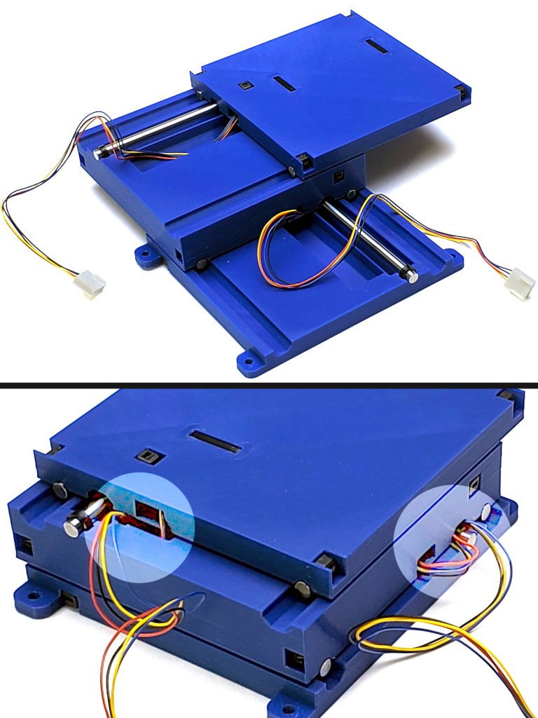
    The folded bundle of wires between the fixed base and lower stage cycles back and forth in a vertical plane pretty close alongside the side without getting into trouble. Breaking the 2d motion of the upper stage into two 1d motions keeps the upper part similarly simple while the lower part is just a few more wires in the bundle that's already there.

    The visible wires feed the motors. The limit switches and their cables are internal, which was an aspiration that came along with the freedom of 3d printing to make parts busy on the inside.

    In that (currently current latest) iteration I wanted to include connectors to disconnect above the deck without pulling any wire up from the lower compartment, and include some provision for managing excess wire within the footprint of the XY stage. Because wires won't be exactly the correct length, and can't be too short, so they will be too long. Especially while "correct length" keeps changing. That makes it much easier to remove/replace the XY stage for whatever reason. I like the functional benefit but that version isn't the answer. Next rev is printing while I'm typing here.

    I had convinced myself to stop thinking about wiring the motors internally because that wasn't going to happen without ditching the (relatively) bulky connector on (some of) these motors. My current thinking is that adapting the design to the motor wires & connectors will net-simplify construction vs requiring to mess with the received motor wiring.

    (aside: That may change. Especially because there are two flavors of the motor I'm using and differences include the length & termination of wires -- and I just received a 'type A' motor with 'type B' wire length and connector so "be sure to order type A" might fail to make the received wiring predictable.

    ...now returning to the previous digression...)


    The Point

    ...of this log entry was to note that, while (distracted from) iterating the 3d printed parts to print a set that doesn't require artisanal artishandcrufting to finish, I think I accidentally figured out how route the motor wires internally. That could be très slick, enable a little more compactness of frame footprint, and get more working parts out of the milling debris field. But I really have to not go down that rabbit hole right now. But I don't not consider it anymore.

  • Teaser: 0.010" slots in 0.020" slots in 0.040" slots

    Paul McClay08/01/2023 at 06:53 0 comments

    Been racing to get stuff done and falling way behind writing about it. :-/

    Here's a quickie look at today's new superpower:

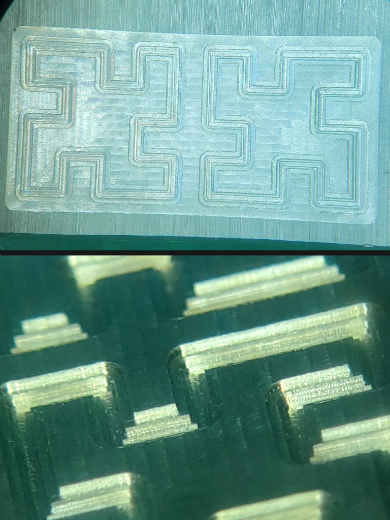
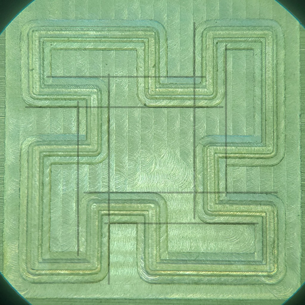
    That's some 0.010" (0.25mm) slots in the bottom of 0.020" (0.5mm) slots in the bottom of 0.040" (1mm) slots in a flat spot on some aluminum.


    Yes, I have tram issues. Project for another day.


    Really it's supposed to be a backlash test. The edges that look like they should line up should actually line up:

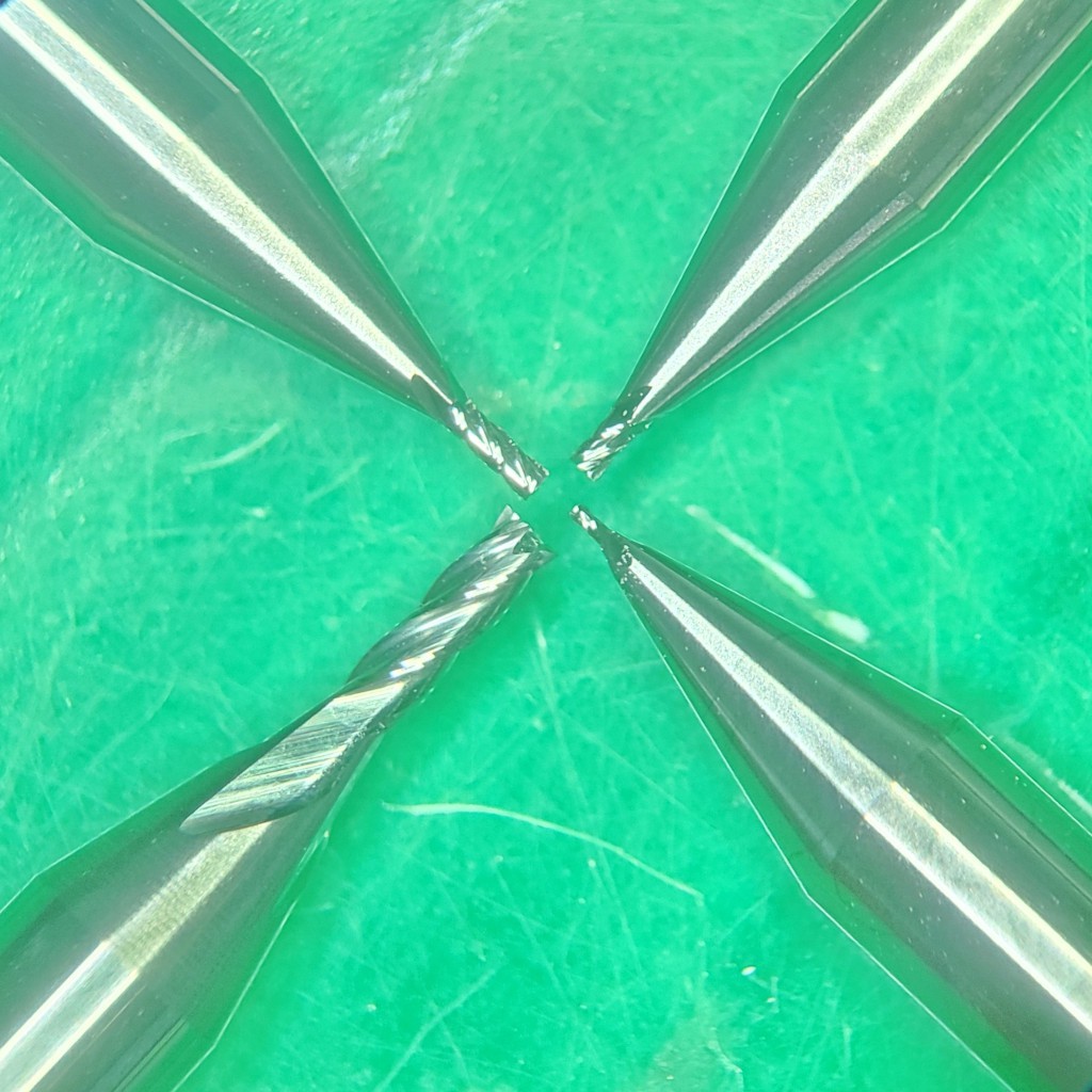
    But I got carried away with some new cutters from a bona fide cutter monger:

    (vs 10/$10 Qi Po cutters)


    I imagined that drawing lines on a picture would be a great way to quantitatively assess backlash. But my microscope has non-trivial lens distortion. Eyeballs cope quite well, but not so much the lines on picture idea. The pic above shows my try at antidistorting with Gimp's lens distortion and perspective tools. Taking measures from images distorted to look right is a little suspect, but presumably lens distortions wouldn't let me tweak offset parallel lines into line.

    Anyhow, the point is that backlash is usefully small. And, though they may stretch the original "very low cost" theme, real cutters rock. 


    Gotta say: "MRRF". Haven't written it up yet but MRRF. (MRRF write-up, now published, precedes this log because started that before starting this)

  • MRRF 2023

    Paul McClay07/29/2023 at 22:28 0 comments

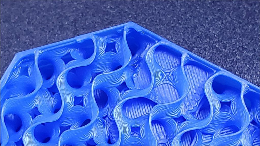
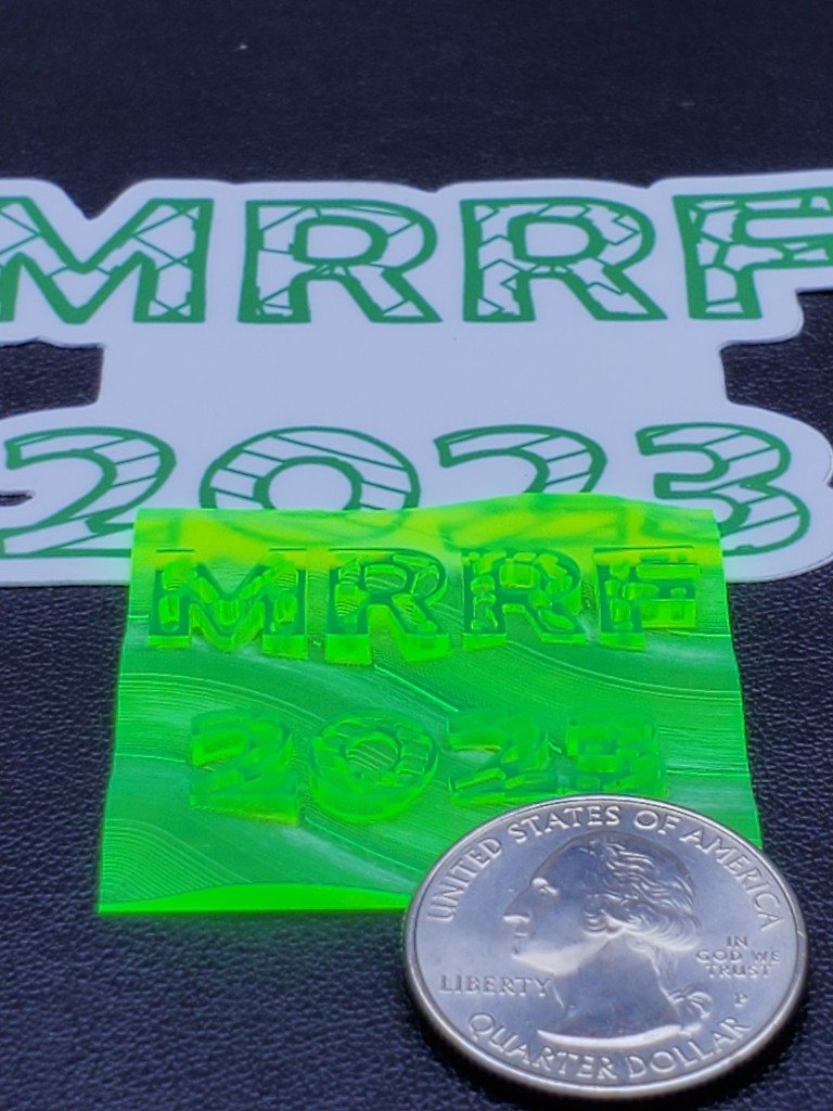
    MRRF 2023 logo in relief over a wavy background
    MRRF 2023 logo in relief over a wavy background

    Last year I kinda accidentally took the laser cut precursor to this CNC to a day of the Midwest RepRap Festival (MRRF) -- the tenth iteration of the oldest/first of the RepRap Fests. I heard lots of very encourating feedback. Stefan of CNC Kitchen took a close look and gave it a video after he got back home.


    MRRF?

    A great drone flythrough video can give a quick visual impression of the event.

    A more expository 2+ minute local TV news exposition includes a brief interview with Sonny Mounicou.


    Going to the Big Show

    Earlier this year, after convincing myself that the 3d printed CNC core would work, and getting more stuff working inside the box, and sorting some ideas for doing all that better, and looking at lots of weeks before the event, I started thinking I might have something that would more directly interest 3d printing people than the laser cut thing. So I actually booked a hotel room and made a plan.

    Then other stuff happened and I got a lot less done than the motivating aspiration, but still had something coherent to show.


    I didn't take a lot of pictures. In fact, at the show I took one picture:

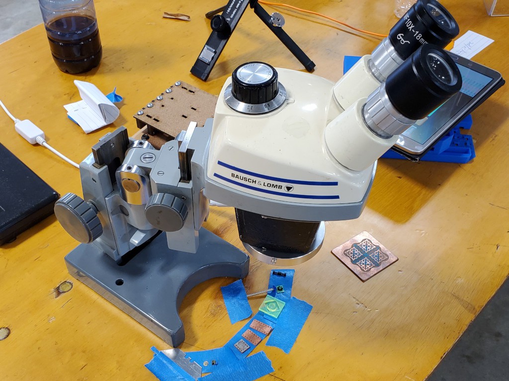
    While packing stuff for the show I thought to take my microscope for grins. That turned out to be very helpful for people to get the 'wow' of the project. After fiddling with it for a while, I got the idea of taping out examples in an arc around the vertical pivot in the stand, which made it very simple to swing the scope head across all the things. For example, Ryan of MPCNC fame appreciated the closer look.

    The microscope helped in part because I didn't really get to keep the mill itself very busy doing its thing. I did manage to cut one little bevel gear that I didn't have an example of. (because I forgot to pack the little differentials!!)


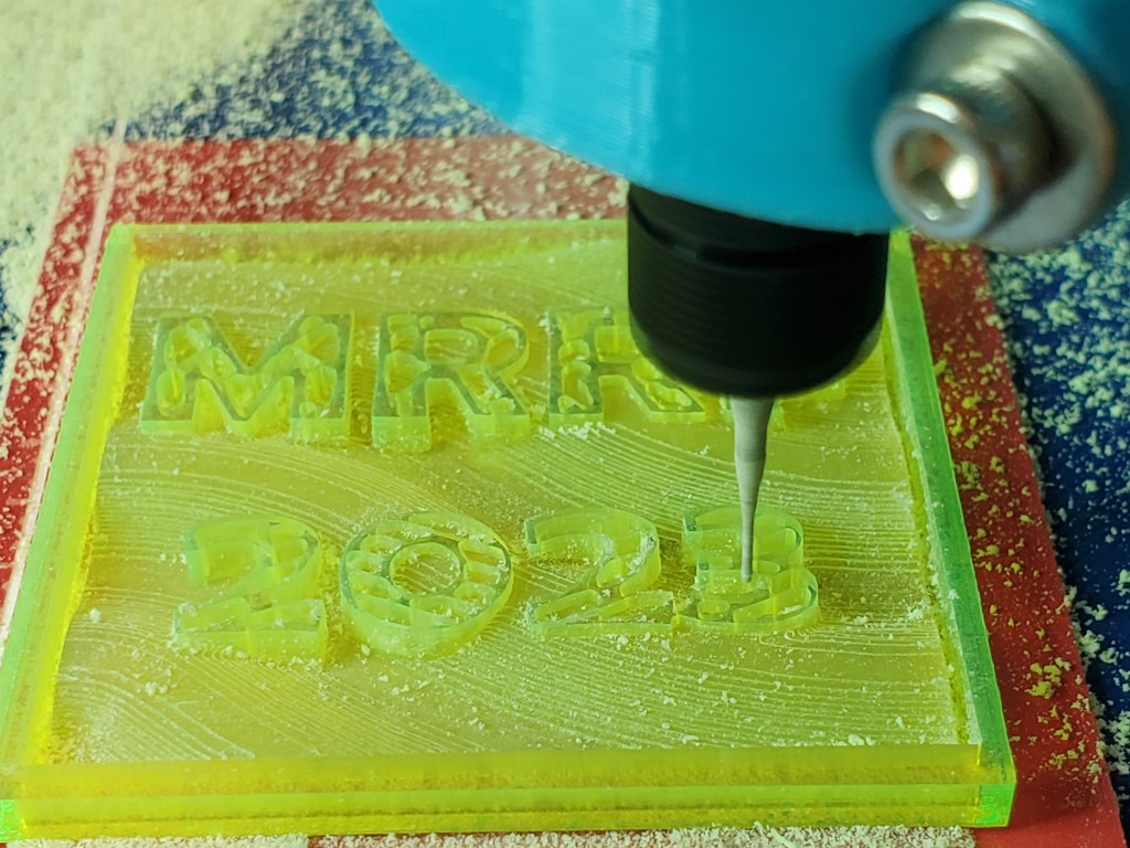
    Early on I cooked up the idea of carving the MRRF logo, but by the time I got that idea mashed through CAD to gcode while frequently distracted (the talking-with-people part) it was too late on Sunday to finish, so I just let it run until it was time to pack up and, unsure that I could actually resume the job successfully, took note of where in the gcode I had to pause it.

    Later (considerably later, because life) I was able to re-register close enough to perfectly with the incompletely cut workpiece and hack the gcode to gracefully pick up where it left off. It worked pretty well. Here's the end of the resumed-and-completed roughing pass:

    The result after a finish pass appears at the top of this page.


    Although I was almost continuously at my table and more often than not talking with someone who stopped for a look, I walked away for a bit Sunday morning to collect an offer of free filament. I recall a drone flying overhead as I walked away -- which turned out to be the fly through video that shows my table sadly deserted.

    There's the back of a display showing example vids and images (some dated and some current from the new machine), the mill, the blue printed parts for the next rev that I hadn't had a chance to assemble before the show, the microscope and light, my laptop probably with the MRRF logo CAD open, etc.

    The filament vendor had already packed up and cleared out, so my absence was for naught.


    I enjoyed talking with lots of people, which also helps break up crusty thinking. I didn't do a very good job of retaining who spent time at my table talking about what. Sorry if you're reading this.

    Things I learned from talking to people:

    • If quicker tool changes matter, multiple rotary tools each set up with one needed bit could help speed up tool changes
      • so I'll have to check repeatability of the Z axis tool clamp
    • for double-sided parts, using a thicker spoil board could relax how precise holes need to be for locator pins if the holes can be deeper
    • While helpful for proof-of-concept, the packing tape hinges really don't count...
    Read more »

  • closer to all-in-one: first try building in new box

    Paul McClay07/27/2023 at 07:52 0 comments

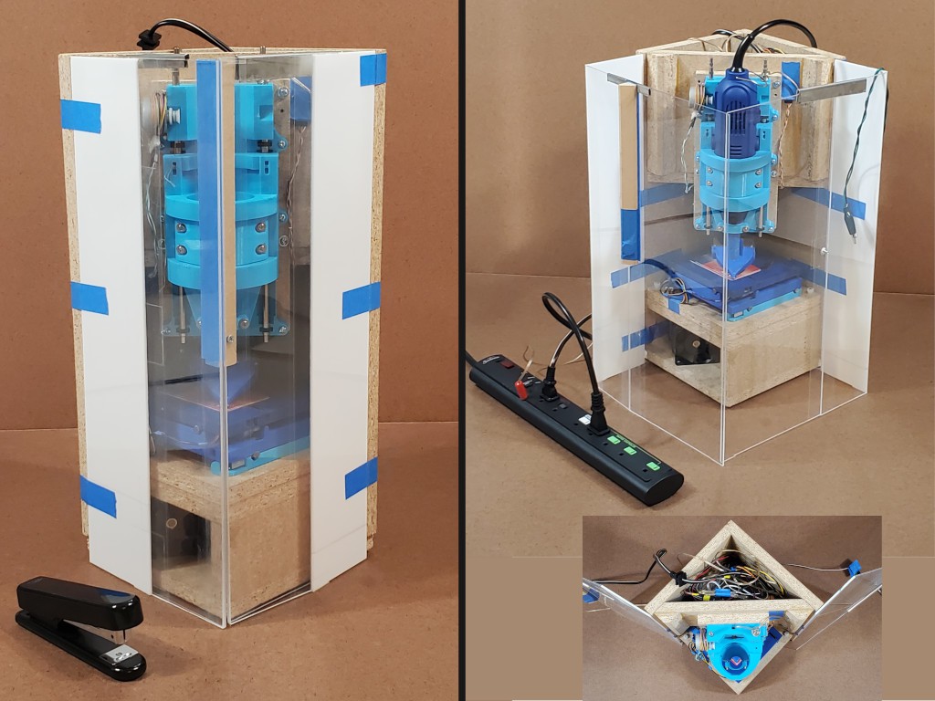
    This log entry describes a completely new enclosure that I kind of accidentally built in the middle of getting this 3d printed re-do of the CNC mechanics to work well enough to believe that it would actually work.

    I've copied it here from #"Desk Accessory" CNC Milling Machine, where it's dated from two days ago, to bring it into this project that I plan to enter in the HaD Prize Gear Up Challenge. 


    Earlier this year..

    The CNC mechanics of #Minamil: a minimal CNC mill had been working encouragingly well for a while but depended on a bunch of other stuff that could be integrated into a compact enclosure but wasn't. A few months ago I made [this] new XY stage with longer leadscrews that couldn't fully extend within the frame/enclosure I was using at that point. In the parallel universe where I have better executive function, I simply put the new CNC mechanics in the old box for initial testing with useful if not maximal X range and -- as it turned out -- more work to get it the new thing working as well as the old thing. Instead I started thinking about a different enclosure and that got out of control for a while before I got back to getting the actual CNC part to work.

    That was a usable first draft and useful for finding pain points to motivate a second try.

    Unfinished bits included:

    • switched AC for spindle still not inside the box, but at least consolidated to a hacked power bar
    • negative ventilation motor wired but filter & outlet not done

    In addition to supporting the CNC parts, the box encloses spaces in the top and bottom. AC power stays isolated in the top part. The bottom part is divided into space for the air filter/fan and space for the control electronics.

    A scavenged unenclosed 5V/12V supply with output through PCB headers and lots of little wires doesn't help the top end look any less chaotic inside. At least it keeps AC away from the rest of the works.

    I figured everything should fit and I've already learned that wires fill more space in real life than in diagrams, but once again underestimated the challenge of connecting lots of things in a small box.


    Doing this once spawned ideas for how to do essentially all of it differently. I really super very much wanted to do a completely new build that I thought some people might appreciate at MRRF this year -- with fairly specific plans and seemingly adequate time. But life. So less time. So when I did get some time I spent it furiously scrambling to finish just a few betterments before MRRF instead of writing log entries. At least I took some pictures while tearing down the "first draft". Then MRRF. Then more life. RIght now I have some time, and a backlog of ideas. But with this year's HaD Prize "Gearing Up" challenge on, it's time to squeeze in some writing too...


    New box, and first try at getting more stuff inside the box

    yes, the picture is a repeat -- because a bunch of words got in here after the first instance. 

    Part of the main idea is for the closed box to be just another box and trivial to stash away wherever without snagging or squishing vulnerable bits.

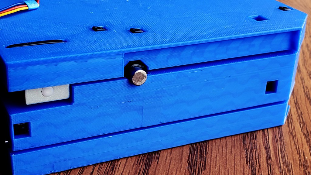
    With the box closed up, I want four flat sides like a plain box with no projections. No hinges, no latches, no buttons, etc. And I want it to be not fragile. In this iteration, moving the hinges away from the corners makes those two corners not fragile. Also the corner where the doors meet is not fragile in compression because the solid panel of each door transfers the load straight into solid material at the hinged corners. For a quickie solution in this case, a single magnet and iron peg (i.e. screw) hold the doors closed, but I have ([1]had?) a plan for a more robust closure. The block in the corner where the doors meet I cut wrong. The idea was to have a single solid piece with the bottom end aligned to rest on top of solid material next to the XY table and the top end in the plane of the...

    Read more »

  • Whence this project?

    Paul McClay07/27/2023 at 07:48 0 comments

    This new project grew from a symbiotic pair of projects with some development history:

    • #Minamil: a minimal CNC mill 
      • Remarkably successful (relative to my expectations) development of, as far as I know, the lowest cost 3-axis CNC mill/router core that actually works
      • Very compact, not very strong, but very precise within limits of shallow cuts with small tools
      • HaD Prize 2021 finalist (via a separate project created per HaDPrize rules)
      • Favorably recognized by unrelated other people
      • Simple CNC elements can work well in a very simple, even crudely built frame
    • #"Desk Accessory" CNC Milling Machine 
      • entirely optional decoration around the "minimal" CNC core
      • aims to build a complete, compact unit to park on a shelf and use at will in ordinary places
      • previously a slow "aspirational" project parked at early proof-of-concept
      • recently bumped with a new build that gets a lot closer to realizing the "desk accessory" idea 

    This new "Minamil 3dp" project introduces a substantially different implementation of the "Minamil" CNC core combined with fresh progress toward "desk accessory" packaging.

    Why spawn a new "Minamil" project?

    I think this new design for 3d printed parts, vs laser cut, combined with new work toward "desk accessory" packaging, represents a step change in potential utility to someone who wants the capabilities of a precise little CNC without committing space for a machine and the mess it throws off. Wider accessibility of 3d printing and much more simple assembly make this design more practical to build. A completely new frame configuration and more comprehensive integration into "desk accessory" packaging make this design more practical to use.

    And...

    I plan to submit this project for the current HaD Prize Gear Up Challenge, where the rules require a new project anyhow. 

  • ToC maybe

    Paul McClay07/25/2023 at 16:57 0 comments

    Because #Minamil: a minimal CNC mill has accumulated enough log entries to be difficult to naviigate, I'll drop this here to stake out space for a Table of Contents in case logs here get unwieldy.

View all 9 project logs

Enjoy this project?

Share

Discussions

Similar Projects

Does this project spark your interest?

Become a member to follow this project and never miss any updates