Close
0%
0%

Work-holding Robotic Arm for Electronic Workshop

Collaborative Robotic Arm Used as Assistant in an Electronic Workshop And Controlled by Voice Commands and Capsense Technology

Similar projects worth following
Using a robotic arm as a third arm can be a very good idea in difficult cases in an electronic workshop. Here I am showing three versions of my project, and the main functions are: a) controlling and depopulating PCBs for harvesting chips, resistors, capacitors, coils, etc; b) pick and place objects such as box; and c) controlling a bottle. In the first version I'm using Artificial Intelligence (AI), with hardware as Alexa Echo Dot, ESP32-WROOM-32, and Arduino Nano 33 BLE Sense; and free open source tools such as FauxmoESP library and Arduino IDE. In the second version, I am using two gripper jaws to improve the performance of the robotic arm tasks with the Infineon PSoC 62S2 Wi-Fi BT Pioneer Kit and ModusToolbox Software. Finally, with a 3D magnetic sensor I have created a mechanism to detect objects that pass through a belt and combining it with any version of a robotic arm we have an object sorter.

Arduino Version

  • This project was a good experience as I used a free tool to control my robot arm with the Alexa Echo Dot device. Also I can increase the voice commands as far as the memory capacity of the processor allows. As you can see, the clamp has large dimensions, so it can hold much larger objects, or even hold them in the right place so that we can work comfortably.

Infineon Version

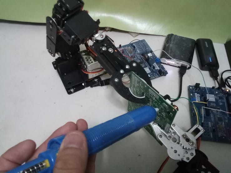
  • In this version of the robotic arm I tried something different. I used capsense technology buttons and sliders to hold PCB boards in my electronics workshop. I had the idea of holding PCB boards to solder and unsolder electronic components.

Sorting Objects

  • In this project the idea is to combine the robotic arm with a 3D magnetic sensor to classify objects. Here I took time to invent the piece that holds the magnetic sensor. The operating mechanism is easy since the moving object rotates the magnetic sensor knob and this activates the robotic arm.


Below you can see a video showing how the prototype works.

sorting-objects.zip

Codes for Sorting Objects With A 3D Magnetic Sensor

x-zip-compressed - 2.66 kB - 09/20/2023 at 01:32

Download

robotic-arm-for-infineon-version.zip

Coder for Infineon version

x-zip-compressed - 2.66 MB - 07/30/2023 at 00:31

Download

robotic-arm-for-arduino-version.zip

Codes for Arduino version

x-zip-compressed - 5.40 kB - 07/30/2023 at 00:30

Download

  • 1 × 6 DOF Robotic Arm
  • 1 × Alexa Echo Dot (3rd Gen)
  • 1 × Arduino NANO 33 BLE Sense
  • 1 × ESP32-WROOM-32
  • 2 × Infineon PSoC™ 62S2 Wi-Fi BT Pioneer Kit

View all 11 components

  • 10. Sorting Objects With A 3D Magnetic Sensor - Part 2

    Guillermo Perez Guillen3 days ago 0 comments

    Below you have the code uploaded to the 3D Magnetic Sensor 2Go board: magnetic_sensor.ino

    // AUTHOR: GUILLERMO PEREZ GUILLEN
    
    
    #include <Tle493d.h>
    
    
    Tle493d Tle493dMagnetic3DSensor = Tle493d();
    void setup() {
      Serial.begin(9600);
      pinMode (3,OUTPUT);
      pinMode (14,OUTPUT);
      digitalWrite (3,LOW);  
      digitalWrite (14,HIGH);    
      while (!Serial);
      
      //If using the MS2Go-Kit: Enable following lines to switch on the sensor
      // ***
       pinMode(LED2, OUTPUT);
       digitalWrite(LED2, HIGH);
       delay(50);
      // ***
        
      Tle493dMagnetic3DSensor.begin();
    }
    
    
    void loop() {
      Tle493dMagnetic3DSensor.updateData();
      Serial.print(Tle493dMagnetic3DSensor.getAzimuth());
      Serial.print("\t");
      if(Tle493dMagnetic3DSensor.getAzimuth()>0) {
        digitalWrite (3,LOW);
        digitalWrite (14,HIGH);
        Serial.println(Tle493dMagnetic3DSensor.getPolar());    
      }
      else {
        Serial.println(-Tle493dMagnetic3DSensor.getPolar());   
        digitalWrite (3,HIGH);
        digitalWrite (14,LOW);    
        delay(1000);
        digitalWrite (3,LOW);
        digitalWrite (14,HIGH); 
      }
    }

    Below is an image of how to mount the 3D Magnetic Sensor 2Go board:

    image

    How does it works?

    1. The magnetic sensor knob can turn and it gives me the Azimuth in radians, to its left it gives positive values and to its right negative values;
    2. I have attached a plastic strip to the magnetic sensor knob to move it every time the rubber ball hit it or the servo returns it to the to the starting position;
    3. When a rubber ball hits the plastic strip, the magnetic sensor knob turns and goes into the area of negative radian values;
    4. Then we activate a pulse through pin 3, and this activates the relay. Finally, this relay activates the user button of the PSoC 62S2 WiFi BT Pioneer board;
    5. The PSoC 62S2 WiFi BT Pioneer board performs two functions: 1) activate servo 7 to returns the magnetic sensor knob into the area of positive radian values, and 2) the robot arm takes the rubber ball and places it in the container;
    6. The cycle repeats until there're no more rubber balls; and
    7. This system can be used to detect, count, and sorter objects.

    image

     Below I show you the code uploaded to the PSoC 62S2 WiFi BT Pioneer board: sorting_objects.c

    // AUTHOR: GUILLERMO PEREZ GUILLEN
    
    
    #include "cy_pdl.h"
    #include "cy_retarget_io.h"
    #include "cyhal.h"
    #include "cybsp.h"
    
    
    /******************************************************************************
     * Macros
     *****************************************************************************/
    #define DELAY_SHORT_MS          (250)   /* milliseconds */
    #define DELAY_LONG_MS           (300)   /* milliseconds */
    #define LED_BLINK_COUNT         (4)
    #define GPIO_INTERRUPT_PRIORITY (7u)
    
    
    /* PWM Frequency */
    #define PWM_FREQUENCY (50u)
    
    
    /* PWM Duty-cycle */
    #define PWM_DUTY_CYCLE_1 (4.58f) //  30 degrees
    #define PWM_DUTY_CYCLE_2 (7.75f) //  90 degrees
    #define PWM_DUTY_CYCLE_3 (12.50f) // 180 degrees
    #define PWM_DUTY_CYCLE_4 (10.92f) // 150 degrees
    #define PWM_DUTY_CYCLE_5 (7.75f) //  90 degrees
    #define PWM_DUTY_CYCLE_6 (4.50f) //  30 degrees
    #define PWM_DUTY_CYCLE_7 (12.50f) //  30 degrees
    
    
    /*******************************************************************************
    * Function Prototypes
    ********************************************************************************/
    static void gpio_interrupt_handler(void *handler_arg, cyhal_gpio_event_t event);
    
    
    /*******************************************************************************
    * Global Variables
    ********************************************************************************/
    volatile bool gpio_intr_flag = false;
    
    
    /*******************************************************************************
    * Function Name: main
    *******************************************************************************/
    int main(void)
    {
        cy_rslt_t result;
        uint32_t count = 0;
        uint32_t delay_led_blink = DELAY_LONG_MS;
    
    
        /* PWM object */
        cyhal_pwm_t servo_1, servo_2, servo_3, servo_4, servo_5, servo_6, servo_7;
    
    
        /* Initialize the device and board peripherals */
        result = cybsp_init();
        
     /* Board init failed. Stop program execution...
    Read more »

  • 9. Sorting Objects With A 3D Magnetic Sensor - Part 1

    Guillermo Perez Guillen3 days ago 0 comments

    In this chapter I'm going to show how to detect objects using the 3D Magnetic Sensor 2Go TLE493D, the robot arm, and the PSoC 62S2 WiFi BT Pioneer Board. In the figure below I show you the electrical diagram used in this chapter.

    image

    In the figure below I show you the electrical connection of this system. In the figure we can see the PSoC 62S2 WiFi BT Pioneer board, the six degrees of freedom robot arm, the 3D Magnetic Sensor 2Go TLE493D, the Servo 7, the ULN2803A IC, the relay, the wooden platform to slide the rubber balls, and the container.

    image

    I had to reviewed the datasheet of my Infineon 3D Magnetic Sensor 2Go. In the image below we can see the components of this board.

    image

    In the image below we can see the board GPIO pinout.

    image

    To program our board, I had downloaded and installed the next software:

    • Arduino IDE
    • USB Driver from SEGGER
    • Library: TLE493D-3DMagnetic-Sensor
    • Board: XMC Microcontroller by Infineon

    The latest version of Arduino IDE is downloaded from: https://www.arduino.cc/en/Main/Software

    We have to download and install the latest version of SEGGER USB driver so that our device works correctly.

    The library TLE493D-3DMagnetic-Sensor is downloaded from: https://github.com/Infineon/TLE493D-W2B6-3DMagnetic-Sensor

    image

    The Microcontroller board is downloaded from the official Infineon site on github. There we will find the instructions for a correct installation: https://github.com/Infineon/XMC-for-Arduino

    In my case, I installed version 1.4.0. Later, in preferences we added the url of the board and installed it: https://github.com/Infineon/Assets/releases/download/current/package_infineon_index.json

    image

  • 8. BOM Cost and Conclusion for Infineon Version

    Guillermo Perez Guillen07/30/2023 at 00:08 0 comments

    Below I show you a estimate BOM cost. However you can reduce the total cost by replacing the rechargeable battery with a power supply.

    BOM cost

    BOM cost

    The Excel document can be downloaded from the download section

    Conclusion

    • In this project I demonstrate the use of capsense sensors in the soldering and desoldering process of a PCB.
    • I have used two Infineon PSoC™ 62S2 Wi-Fi BT Pioneer Kit boards, and they were programmed with ModusToolbox 3.0

  • 7. Unsoldering Components With Infineon Version

    Guillermo Perez Guillen07/30/2023 at 00:03 0 comments

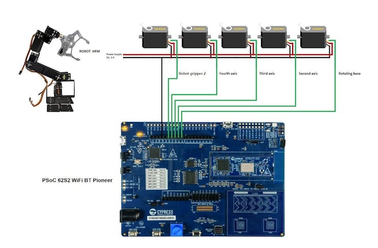
    Now, I show you how to use the CAPSENSE technology to unsolder components, and again using the PSoC 62S2 WiFi BT Pioneer Kit board. Below I show you the schematic diagram.

    Schematic Diagram

    Schematic diagram

    Schematic diagram

    How does it work?

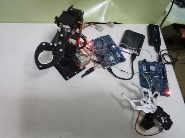
    • Here I will use the device created in section 3. This gripper-1 will be used to hold a part of the board on which I will desolder a component.

    The gripper-1 also helped me to desolder components on a PCB board.

    The gripper-1 also helped me to desolder components on a PCB board.

    • When I turn on the system the robot arm is positioned according to the initial configuration. That is, servo 1 moves to 30 degrees from the origin.

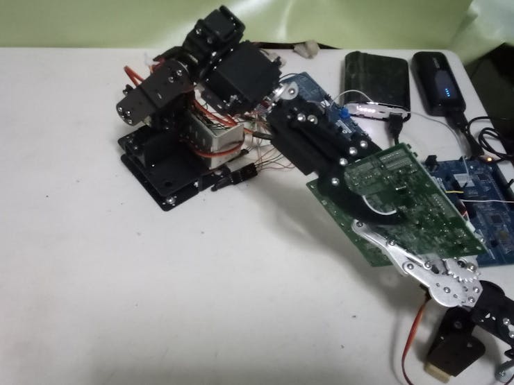
    Between two grippers the PCB board is fixedly clamped as shown in the picture

    Between two grippers the PCB board is fixedly clamped as shown in the picture

    • When I press the capsense BTN0 button, servo 1 moves to 165 degrees from the origin to hold the PCB with gripper-2. Next, servo 1 moves to 100 degrees from the origin to face gripper 2 to gripper-1. Now I can hold the PCB with both grippers as shown in the attached image.

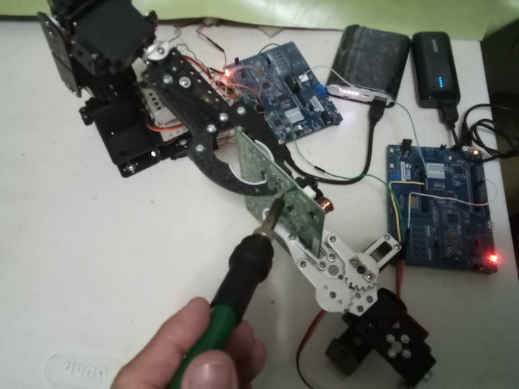
    Its time to desolder a component with the soldering iron

    Its time to desolder a component with the soldering iron

    • Since the PCB board is firmly holded, then I can desolder components comfortably. When I finish desoldering I can open the griper-1.

    Finally we use the solder extractor to remove the component

    Finally we use the solder extractor to remove the component

    • When I press the BTN1 capsense button, servo 1 moves from 100 degrees from the origin to 30 degrees. Here the robot arm releases the PCB board and returns to the position indicated in point 2.
    • Additionally, I have configured servo 4 to rotate the gripper with the Capsense sliding bar. This movement can only be done when the robot arm is in the initial position indicated in point 2. When I move my finger to the SLD 0 position, the gripper-2 tilts 90 degrees from the origin.

    Prgramming With ModusToolbox

    Again as in section 4, I have used the "CAPSENSE_Buttons_and_Slider" example and named the project as Unsoldering_Components_Using_Capsense.

    We repeat the same steps already seen to program the other PSoC 62S2 board as a component desoldering iron

    We repeat the same steps already seen to program the other PSoC 62S2 board as a component desoldering iron

    Finally, I have modified the "led.c" code. Below I show you the full code.

    // AUTHOR: Guillermo Perez Guillen
    
    /*******************************************************************************
    * Header files includes
    *******************************************************************************/
    #include "cybsp.h"
    #include "cyhal.h"
    #include "led.h"
    #include <stdio.h> // added
    #include <math.h>
    
    /*******************************************************************************
    * Global constants
    *******************************************************************************/
    #define PWM_LED_FREQ_HZ    (1000000lu)  /* in Hz */
    #define GET_DUTY_CYCLE(x)    (100 - x)
    
    /*******************************************************************************
    * Global constants
    *******************************************************************************/
    led_state_t led_state_cur = LED_OFF;
    cyhal_pwm_t pwm_led;
    cyhal_pwm_t servo_1; // robot arm
    cyhal_pwm_t servo_2;
    cyhal_pwm_t servo_3;
    cyhal_pwm_t servo_4;
    cyhal_pwm_t servo_5; // robot gripper-2
    
    /******************************************************************************
     * Servo Macros - added
     *****************************************************************************/
    
    /* PWM Frequency */
    #define PWM_FREQUENCY (50u)
    
    /* PWM Duty-cycle */
    #define PWM_DUTY_CYCLE_1 (4.44f) //  30 degrees
    #define PWM_DUTY_CYCLE_2 (8.02f) //  100 degrees
    #define PWM_DUTY_CYCLE_3 (10.76f) // 150 degrees
    #define PWM_DUTY_CYCLE_4 (8.02f) //  100 degrees
    #define PWM_DUTY_CYCLE_5 (3.48f) //  10 degrees - robot gripper-2
    
    /*******************************************************************************
    * Function Name: update_led_state
    ********************************************************************************
    * Summary:
    *  This function updates the LED state, based on the touch input.
    *
    * Parameter:
    *  ledData: the pointer to the LED data structure
    *
    *******************************************************************************/
    void update_led_state(led_data_...
    Read more »

  • 6. Soldering Components With Infineon Version

    Guillermo Perez Guillen07/29/2023 at 23:54 0 comments

    In this section I will show you how to use the CAPSENSE technology to solder components, and using the PSoC 62S2 WiFi BT Pioneer Kit board. Below I show you the schematic diagram.

    Schematic Diagram

    Schematic diagram

    Schematic diagram

    How does it work?

    • Every time I need to hold a PCB to solder a component, I simply have to move my finger on the sliding bar to SLD 4 position. Then the gripper-1 is closed.

    Here we can see the way to hold the PCB board to solder a resistor

    Here we can see the way to hold the PCB board to solder a resistor

    • When I need to release a PCB after soldering a component, I simply have to move my finger on the sliding bar to SLD 0 position. Then the gripper-1 is opened.

    Moment when I use the soldering iron to solder pins

    Moment when I use the soldering iron to solder pins

    • The pinout of this board is shown below.

    PSoC 62S2 pinout

    PSoC 62S2 pinout

    Programming With ModusToolbox

    Here I have used the "CAPSENSE_Buttons_and_Slider" example. First select the board in: File - New - ModusToolbox Application

    Selecting the model CY8CKIT-062S2-43012

    Selecting the model CY8CKIT-062S2-43012

    So I changed the application name to Soldering_Components_Using_Capsense as shown below:

    Selecting the sample code that served as a model for my project

    Selecting the sample code that served as a model for my project

    Once the project is created, you have to change the code of the led.c file to:

    // AUTHOR: Guillermo Perez Guillen
    
    /*******************************************************************************
    * Header files includes
    *******************************************************************************/
    #include "cybsp.h"
    #include "cyhal.h"
    #include "led.h"
    #include <stdio.h> // added
    #include <math.h>
    
    /*******************************************************************************
    * Global constants
    *******************************************************************************/
    #define PWM_LED_FREQ_HZ    (1000000lu)  /* in Hz */
    #define GET_DUTY_CYCLE(x)    (100 - x)
    
    
    /******************************************************************************
     * Servo Macros - added
     *****************************************************************************/
    
    /* PWM Frequency */
    #define PWM_FREQUENCY (50u)
    
    /* PWM Duty-cycle */
    #define PWM_DUTY_CYCLE_1 (4.58f) //  30 degrees
    
    /*******************************************************************************
    * Global constants
    *******************************************************************************/
    led_state_t led_state_cur = LED_OFF;
    cyhal_pwm_t pwm_led;
    cyhal_pwm_t servo_1; // added
    
    /*******************************************************************************
    * Function Name: update_led_state
    ********************************************************************************
    * Summary:
    *  This function updates the LED state, based on the touch input.
    *
    * Parameter:
    *  ledData: the pointer to the LED data structure
    *
    *******************************************************************************/
    void update_led_state(led_data_t *ledData)
    {
        if ((led_state_cur == LED_OFF) && (ledData->state == LED_ON))
        {
            cyhal_pwm_start(&pwm_led);
            led_state_cur = LED_ON;
            ledData->brightness = LED_MAX_BRIGHTNESS;
            //printf("brightness high!!!\r\n\n");
        }
        else if ((led_state_cur == LED_ON) && (ledData->state == LED_OFF))
        {
            cyhal_pwm_stop(&pwm_led);
            led_state_cur = LED_OFF;
            ledData->brightness = 0;
            //printf("brightness low!!!\r\n\n");
        }
        else
        {
        }
    
        if ((LED_ON == led_state_cur) || ((LED_OFF == led_state_cur) && (ledData->brightness > 0)))
        {
            cyhal_pwm_start(&pwm_led);
            uint32_t brightness = (ledData->brightness < LED_MIN_BRIGHTNESS) ? LED_MIN_BRIGHTNESS : ledData->brightness;
    
            uint32_t servo_control_gripper_1 = brightness;
            uint32_t PWM_DUTY_CYCLE_GRIPPER_1 = 0.00003 * pow(servo_control_gripper_1, 2) + 0.0472 * servo_control_gripper_1 + 3;
    
            /* Drive the LED with brightness */
            cyhal_pwm_set_duty_cycle(&pwm_led, GET_DUTY_CYCLE(brightness),
                                     PWM_LED_FREQ_HZ);
            cyhal_pwm_set_duty_cycle(&servo_1, PWM_DUTY_CYCLE_GRIPPER_1, PWM_FREQUENCY); // robot gripper
            cyhal_pwm_start(&servo_1); // robot gripper
    
            led_state_cur = LED_ON;
        }
    }
    
    /**************************************************...
    Read more »

  • 5. Getting Started With Infineon Version

    Guillermo Perez Guillen07/29/2023 at 23:49 0 comments

    In this section we will use ModusToolbox 3.0 which has enhanced support for multi-core project workflow. The release features dual-core device support, a new graphical tool for customer board support package (BSP) development, infrastructure support for ModusToolbox Packs and backend system improvements.

    ModusToolbox 3.0

    ModusToolbox 3.0

    About ModusToolbox software you can find the documentation here: https://www.infineon.com/cms/en/design-support/tools/sdk/modustoolbox-software/

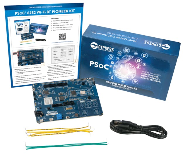
    The PSoC™ 62S2 Pioneer Kit features the PSoC™ 62 MCU (CY8C624ABZI-S2D44): 150-MHz Arm Cortex-M4 and 100-MHz Arm Cortex-M0+ cores, 2MB of Flash, 1MB of SRAM, Secure Digital Host Controller (SDHC) supporting SD/SDIO/eMMC interfaces, programmable analog blocks, programmable digital blocks, Full-Speed USB, a serial memory interface, a PDM-PCM digital microphone interface, and industry-leading capacitive-sensing with CAPSENSE™.

    Documentation: https://www.infineon.com/cms/en/product/evaluation-boards/cy8ckit-062s2-43012/

    The PSoC™ 62S2 Pioneer Kit

    The PSoC™ 62S2 Pioneer Kit

    CAPSENSE™ technology:

    • Doesn't involve moving parts and will not wear out over time.
    • Can be completely sealed to prevent moisture from seeping in.
    • Doesn't require force to operate.
    • Results in reduced BOM cost.
    • Offers more flexibility in button shape, size, and graphical representation for your overall design.

    Controlling Servo Motor With ModusToolbox

    Servo motors are electromechanical devices that have the ability to control the angular position of their axis, their operation consists of receiving the information of the desired angle through the pulse width of a PWM signal to bring the axis to said position. According to the datasheet of the SG995 we have this graph that helps us to control the PWM signal and the duty cycle.

    SG995 Datasheet

    SG995 Datasheet

    The position of the axis of the motor depends on the duty cycle of the signal. There are some standard calculations for degree rotation. If the PWM signal is high for 0.5ms in a single cycle, the axis moves to zero degrees. To rotate the motor axis to 90 degrees, the signal should be high for 1.5ms. Similarly, a 2.5ms ON-time signal leads to 180-degree axial position. In this way, we can measure and control our servo motor to desired degrees.

    Correlation between the duty cycle with the angle of the servo

    Correlation between the duty cycle with the angle of the servo

    According to the example "HAL PWM square wave" we see that it uses a library to control the PWM signal and the duty cycle. I just have to insert the values of the frequency and the duty cycle percentage. By interpolation, we can calculate: if 20 ms is 100% duty cycle, then 0.5 ms is 2.5% duty cycle. Similary 1.5 ms is 7.5% duty cycle, and 2.5 ms is 12.5% duty cycle.

    I experimented with this data, and the only value I adjusted was the 0° angle at 3% duty cycle, because the servo was vibrating and making noise at 2.5%. The final data is shown below:

    Correlation of the values with the percentage of the duty cycle

    Correlation of the values with the percentage of the duty cycle

    Fitting a data set to a trend line using excel

    The data between the angle and the duty cycle percentage are not linear, so I found a method to get a formula with excel.

    • First we make a scatterplot using the data from the table above. The x value corresponds to the angle, and the y value corresponds to the duty cycle percentage.
    • Then, on a point of the graph we click with the right mouse button and select add trendline.
    • In the drop down menu I chose polynomial trendline option with degree 2.
    • Finally, through the displayed menu I ask Excel to display equation on chart. Below I show you the final result.

    Obtaining the formula to calculate the percentage of the duty cycle (y), if I have the angle that the servo rotates (x)

    Obtaining the formula to calculate the percentage of the duty cycle (y), if I have the angle that the servo rotates (x)

    This is the formula that I will use in the next sections to move each servo of the robotic arm.

  • 4. Test and Conclusion for Arduino Version

    Guillermo Perez Guillen07/29/2023 at 23:35 0 comments

    Test

    In the video below I show you the tests with a PCD board and harvesting a connector.

    Now, pick and place a box containing a lamp.

    Finally, in the video below I show you the tests with a water bottle

    Conclusion

    • I have used free tools to develop a robotic arm that can help us in the tasks of an electronic workshop, eg:
    • Achieve desoldering unusable PCB boards, where I have recovered and reused hundreds of components such as chips, capacitors, and resistors. The robotic arm has a stall torque of 8.5 kgfxcm (4.8V) and 10 kgfxcm (6V) in each servo, so the force used is less in manipulating PCB boards;
    • The test of picking and moving a box with a lamp, I have used it as an experimental test, since I would really like it to pick and place the unsoldered electronic components, but in this case I will have to make modifications in the robotic arm clamp to achieve this effect; and
    • The test of holding and moving a bottle has also served as an experimental test, since my intention is that it provides me with isopropyl alcohol to clean PCB boards and desoldered electronic components. Even I could develop a small fire system with this idea.
    • Finally, I also have plans for the future with this innovative idea, but I will publish these in my next log.

  • 3. Software for Arduino Version

    Guillermo Perez Guillen07/29/2023 at 23:28 0 comments

    Prerequisites

    The FauxmoESP

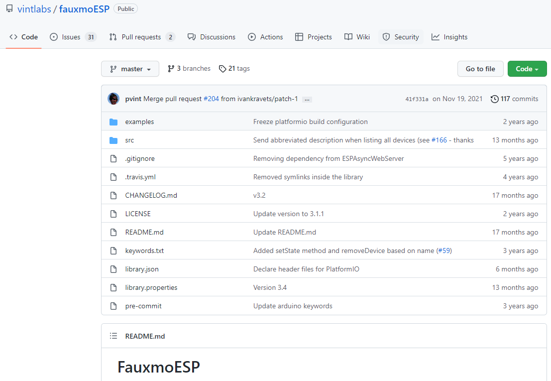
    To control the ESP32 with Alexa Echo Dot, you need to install the FauxmoESP library. This library emulates a Belkin Wemo device, allowing you to control your ESP32 using this protocol. This way, the Echo Dot instantly recognizes the device, after uploading the code, without any extra skills or third party services. You can read more about FauxmoESP here:

    https://bitbucket.org/xoseperez/fauxmoesp/src/master/

    https://github.com/vintlabs/fauxmoESP

    Installing the ESP32 Board in Arduino IDE

    In order to upload code to your ESP32 using Arduino IDE, you should install an add-on for the Arduino IDE that allows you to program the ESP32 using the Arduino IDE and its programming language. You can read more about Installing the ESP32 Board in Arduino IDE here:

    https://randomnerdtutorials.com/installing-the-esp32-board-in-arduino-ide-windows-instructions/

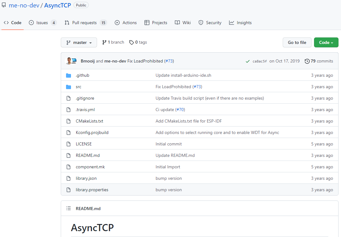
    Installing the AsyncTCP Library

    You also need to install the AsyncTCP Library. You can read more about Installing the AsyncTCP Library here:

    https://github.com/me-no-dev/AsyncTCP

    Code for ESP32 board

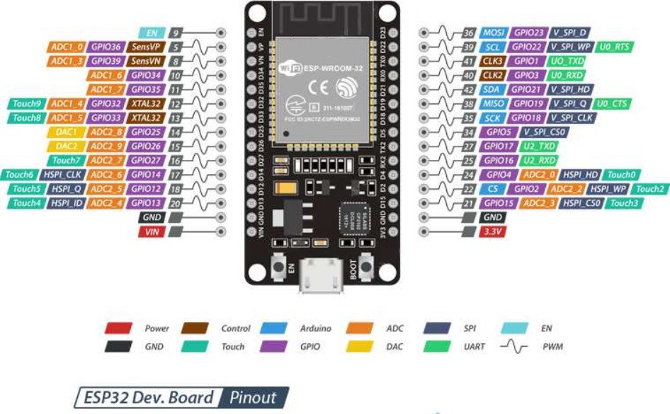
    To programming the ESP32-WROOM-32 I have used next code: robot-arm-esp32.ino

    // AUTHOR: GUILLERMO PEREZ GUILLEN
    
    #include <Arduino.h>
      #include <WiFi.h>
      #define LED_BUILTIN 2 // define the GPIO 2 as LED_BUILTIN  
      #define RELAY_PIN_3 17  // LAMP 3 
      #define RELAY_PIN_4 18  // LAMP 4
      #define RELAY_PIN_5 19  // LAMP 5 
      #define RELAY_PIN_6 21  // LAMP 6        
    
    #include <fauxmoESP.h>
    #define SERIAL_BAUDRATE 115200
    #define WIFI_SSID "*********"
    #define WIFI_PASS "************"
    #define LAMP_1 "box" // 
    #define LAMP_2 "breadboard" // 
    #define LAMP_3 "bottle" // 
    //#define LAMP_4 "lamp four" // 
    
    fauxmoESP fauxmo;
    
    // Wi-Fi Connection
    void wifiSetup() {
      // Set WIFI module to STA mode
      WiFi.mode(WIFI_STA);
    
      // Connect
      Serial.printf("[WIFI] Connecting to %s ", WIFI_SSID);
      WiFi.begin(WIFI_SSID, WIFI_PASS);
    
      // Wait
     
      Serial.println();
    
      // Connected!
      Serial.printf("[WIFI] STATION Mode, SSID: %s, IP address: %s\n", WiFi.SSID().c_str(), WiFi.localIP().toString().c_str());
    }
    
    void setup() {
    
      // Init serial port and clean garbage
      Serial.begin(SERIAL_BAUDRATE);
      Serial.println();
    
      // Wi-Fi connection
      wifiSetup();
    
      // LED
    
      pinMode(LED_BUILTIN, OUTPUT); // initialize GPIO pin 2 LED_BUILTIN as an output.
      digitalWrite(LED_BUILTIN, HIGH);   // turn the LED on 
      
    
      // Add virtual devices
      fauxmo.addDevice(LAMP_1);
      fauxmo.addDevice(LAMP_2);
      fauxmo.addDevice(LAMP_3); 
    //  fauxmo.addDevice(LAMP_4);
    
      fauxmo.onSetState([](unsigned char device_id, const char * device_name, bool state, unsigned char value) {
        // Callback when a command from Alexa is received. 
        // You can use device_id or device_name to choose the element to perform an action onto (relay, LED,...)
        // State is a boolean (ON/OFF) and value a number from 0 to 255 (if you say "set kitchen light to 50%" you will receive a 128 here).
        // Just remember not to delay too much here, this is a callback, exit as soon as possible.
        // If you have to do something more involved here set a flag and process it in your main loop.
            
        Serial.printf("[MAIN] Device #%d (%s) state: %s value: %d\n", device_id, device_name, state ? "ON" : "OFF", value);
    
    ////////// MOVE THE BOX //////////
        if ( (strcmp(device_name, LAMP_1) == 0) ) {
          Serial.println("RELAY 1 switched by Alexa");
          if (state) {
            digitalWrite(RELAY_PIN_1, HIGH);
            delay(1000);
            digitalWrite(RELAY_PIN_1, LOW);
          } else {
            digitalWrite(RELAY_PIN_2, HIGH);
            delay(1000);
            digitalWrite(RELAY_PIN_2, LOW);
          }
        }
    
    
    void loop() {
      static unsigned long last = millis();
      if (millis() - last > 5000) {
        last = millis();
        Serial.printf("[MAIN] Free heap: %d bytes\n", ESP.getFreeHeap());
      }    
    }

     Dont forget to insert the credentials of your modem in the Wi-Fi.

    #define WIFI_SSID "*********"

    #define WIFI_PASS "************"

    Code for Arduino NANO 33 BLE Sense board

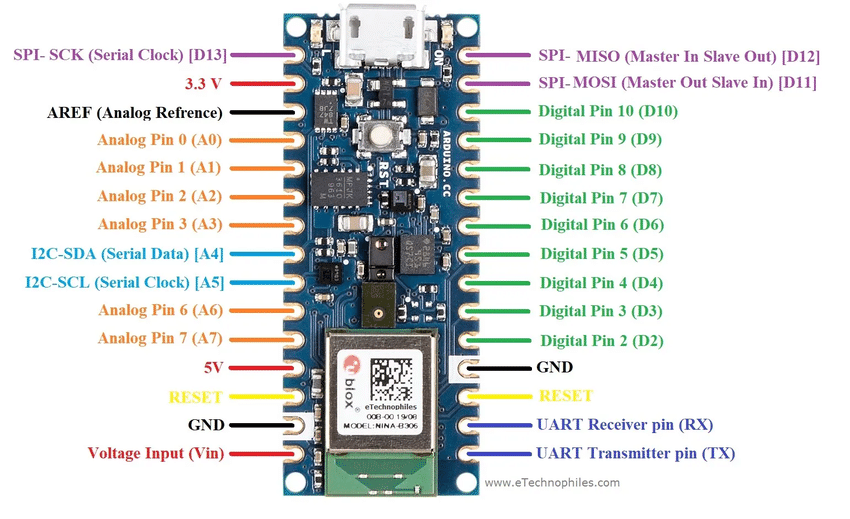
    To programming the Arduino NANO 33 BLE Sense, I have used next code: ...

    Read more »

  • 2. Hardware for Arduino Version

    Guillermo Perez Guillen07/29/2023 at 23:27 0 comments

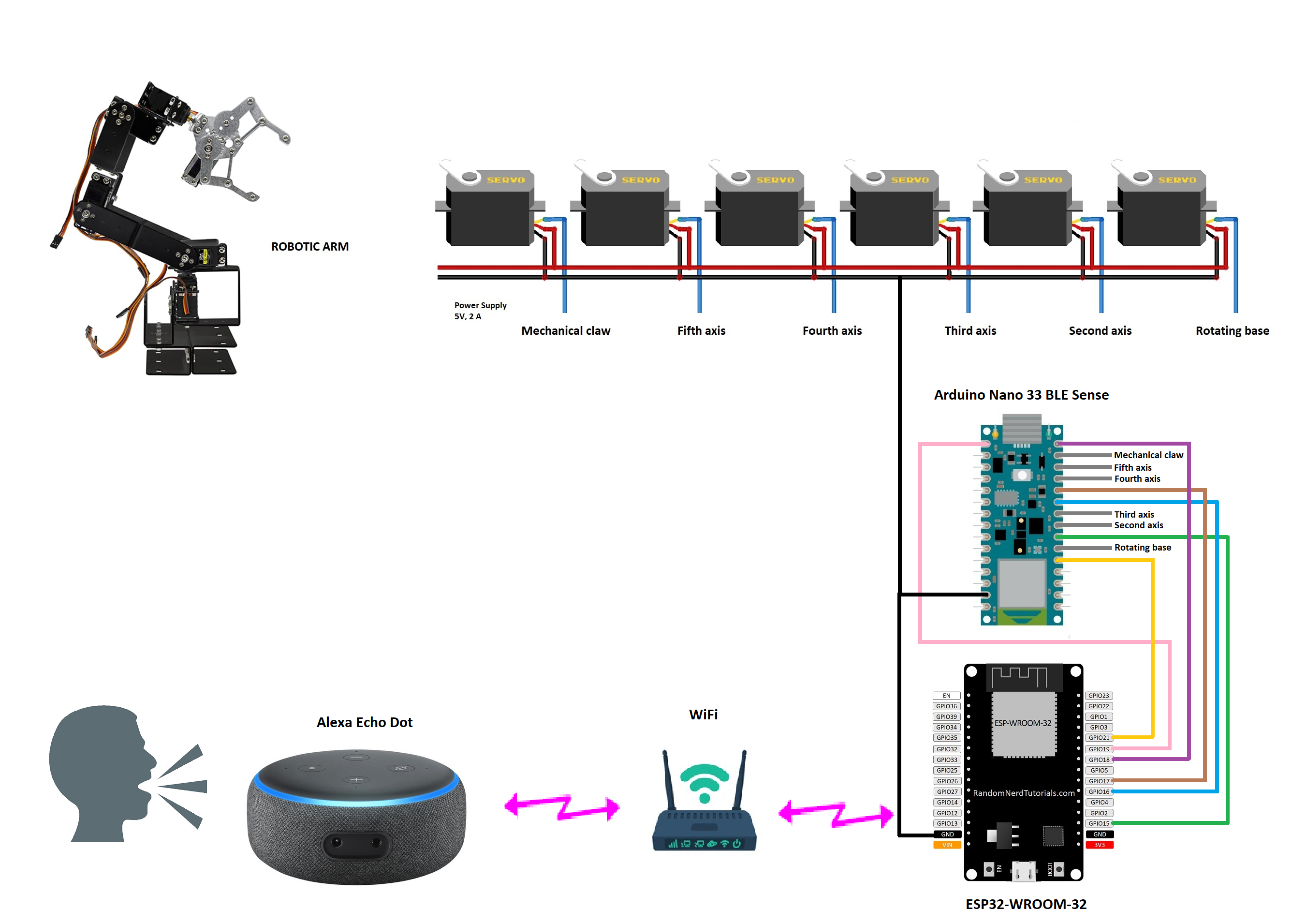
    The schematic diagram below shows the electrical connections of the electronic components.

    How does it work?

    • We use voice commands to perform three functions: 1) controlling a bottle; 2) controlling a board; and 3) controlling a box.
    • The voice commands are activated through Alexa Echo Dot, and they reach the ESP32-WROOM-32 board via WiFi.
    • Finally, these voice commands are transmitted to the Arduino Nano 33 BLE Sense board, which controls the robot arm.

  • 1. Introduction

    Guillermo Perez Guillen07/29/2023 at 23:22 0 comments

    A cobot, or collaborative robot, is a robot intended for direct human robot interaction within a shared space, or where humans and robots are in close proximity. Cobot applications contrast with traditional industrial robot applications in which robots are isolated from human contact. Cobot safety may rely on lightweight construction materials, rounded edges, and inherent limitation of speed and force, or on sensors and software that ensures safe behavior.

    Cobots can have many uses, from information robots in public spaces, logistics robots that transport materials within a building, to industrial robots that help automate unergonomic tasks such as helping people moving heavy parts, or machine feeding or assembly operations. In my case, I'm talkink about a cobot for electronic workshop, which is a collaborative robot or a robot intended for direct human robot interaction within a shared space, or where humans and robots are in close proximity. Reference: https://en.wikipedia.org/wiki/Cobot

View all 10 project logs

  • 1
    Software apps and online services
    • Arduino IDE
    • The FauxmoESP library
    • the AsyncTCP Library
    • Infineon ModusToolbox Software
  • 2
    Hand tools and fabrication machines
    • Digital Multimeter
    • Soldering iron (generic)
    • Desoldering pump
    • Switching Power Supply - 330W
  • 3
    Arduino version logs

    2. Hardware for Arduino Version

    3. Software for Arduino Version

    4. Test and Conclusion for Arduino Version

View all 5 instructions

Enjoy this project?

Share

Discussions

Guillermo Perez Guillen wrote 07/30/2023 at 00:49 point

This idea helps to solve the challenge of the "Gearing Up" category, since it uses the robot gripper jaws in a novel way in an electronic workshop. It also teaches us two opensource versions for different users preferences: Arduino version with AI and Infineon version with capsense buttons.

  Are you sure? yes | no

Guillermo Perez Guillen wrote 07/30/2023 at 00:42 point

In an electronics workshop this project helps to solve the problem of extracting components from old PCB boards, such as resistors, capacitors, diodes, transistors, inductors, chips, etc. for later reuse or recycling.

  Are you sure? yes | no

Similar Projects

Does this project spark your interest?

Become a member to follow this project and never miss any updates