 Adam Krovina
At first we needed to verify a certain type of solenoid valve, nozzle, working pressure.. We needed a valve acting quick enough so that the pixel size could be reasonable. I've got a previous good experience with a certain type, which proved to be sufficient. It can be reliably opened by a 5 ms pulse. We use FET transistor to drive the coil, not a mechanical relay.
Our first test rig was hand-held and used only 1 valve. So we have painted just dots or dashes to check both the valve and nozzle capability. Once we agreed it is sufficient and usable, we have decided to purchase 6 more valves and FET switching boards to create a "print head" of 7 valves in total.
We have been thinking a lot about how to pressurize water. We have used compressed air at about 2 bar to push the water out of the bottle at the first test with one valve. Later we wanted to use the 5 l bottle, which did not withstand the pressure well, so we moved on the windscreen water pump from a car. The pump generates pressure of almost 1.5 bar at 12 V, 3 A. Looks good.
With the pump after the reservoir, there is no extra pressure in the reservoir. We just needed to ensure there is water in the pump, so it does not run dry. This has proven to be a bit tricky. We did not want to put the bottle up-side-down, nor to drill a hole at the bottom. So we have added a mechanical valve at the hose after the pump. Then there is a short hose coming from the top of the bottle. If we need to push water into the system, we open the valve and blow into the short hose to push water into the system. When the water is coming out at the bottom, we close the valve and the system is ready.
We needed some kind of encoder to find out exact speed or distance traveled, so we could paint the pixels evenly, independent of bike speed. And we remember, that the bike has a dynamo in the front wheel. We have counted, that there are fourteen periods of the AC voltage per revolution of the wheel. The voltage is around 10 Volts, dependent on speed. I have connected an optocoupler board input to the dynamo, there was around 3 kOhm resistor in series on that board. It worked, I got 14 impulses per rotation. But the 14 impulses was not enough.. So I have connected another optocoupler input in the opposite direction, so I could also detect the negative half-period as another impulse. I had to fight the original board layout, where the grounds of the four inputs were connected together, so connecting 2 inputs in parallel & reversed polarity would result in a short circuit. After successfully hacking the opto-in board, I finally got 28 pulses per revolution. That has proven to be quite good resolution we have used directly, without any interpolation. Each dynamo pulse is a row of pixels - this has simplified the code a bit.
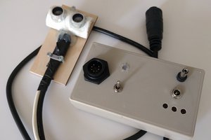
The first test with seven nozzles was already a successful text print "BIKE PRINTER". We have worked a bit on tuning the nozzles, so the pixels are well in-line. We have also tuned the valve pulse length, the final value was 7 ms. The printing is triggered by a manual switch mounted on the handlebar. The firmware has 8 configurable strings to be printed out. The firmware runs on an arduino nano. There is a command line interface on the UART. We have used an ESP32 board as a Wifi hotspot, so we could connect with a smartphone with terminal app to send commands like new strings to be printed.
We have attended a Critical mass on 28.7.2023 in Bratislava, when the bike printer was just finished. The printer worked all the time, we have printed also some birthday wish, random people liked to have their names printed to take a picture with.. I'd say it was a successful little crazy project. Thanks to Bryan, who made the truck printer and inspired us :)
 Pauli Salmenrinne
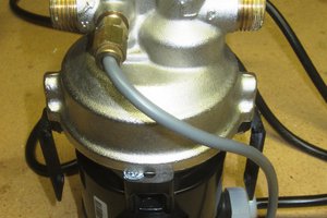
 ogdento
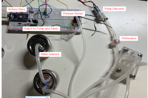
 BastelBaus
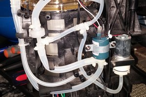
 AndyMac