 Takahiro
Introduction
"Interactive Hand Sensor" can be detected with a resolution of 0.4~0.8 inch (1~2 cm).Can be applied to non-contact switches, non-contact touch panels, motion detection, etc.
8 sensors from 0 to 7 channels can be sensed in the shortest 1.2 milliseconds

How it works
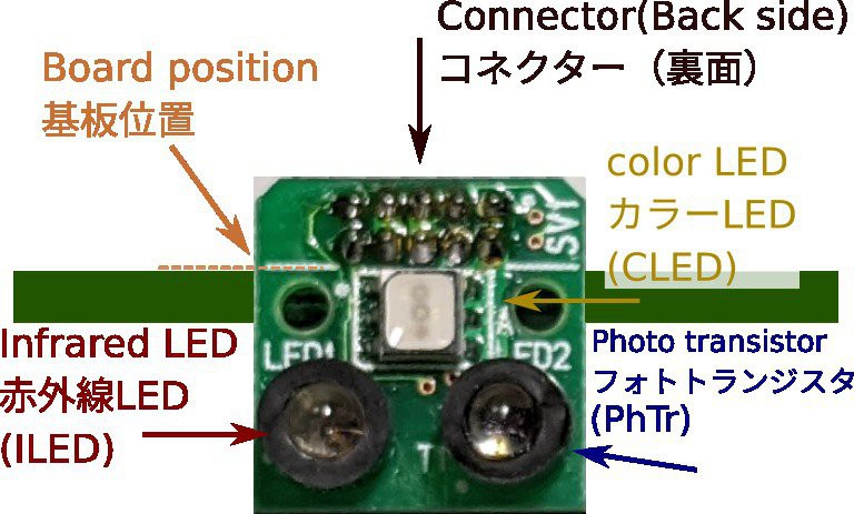
The principle is "Switching Photo Reflector".
The photo transistor converts the reflected light into current, and the resistor converts it into voltage.
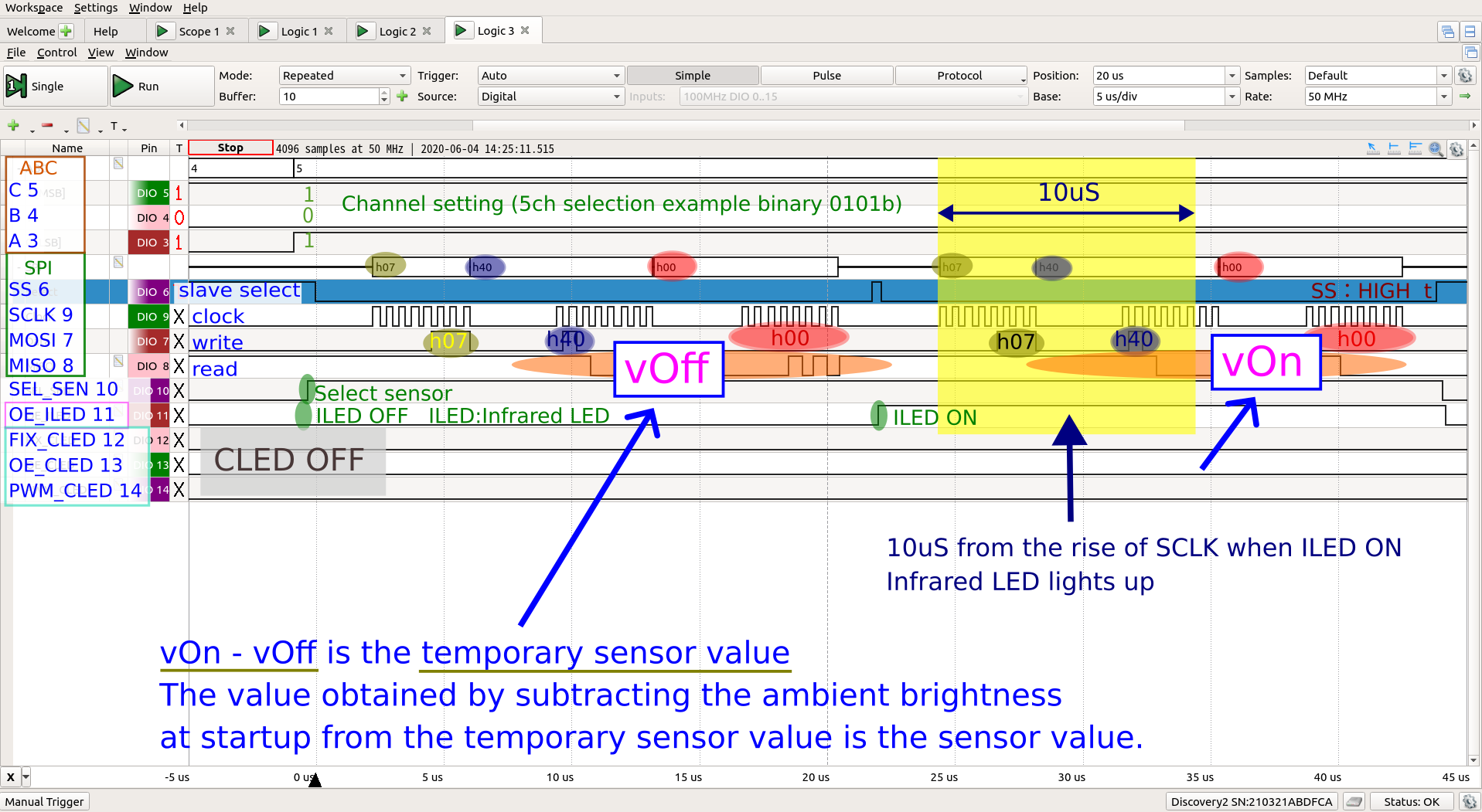
When reading the voltage with the AD converter, the infrared LED is lit at the SCLK timing of SPI Interface. It is driven for 10 microseconds without a current limiting resistor and emits strong light at a current of about 1.5A.
Distance accuracy is poor. The intensity of the reflected light is not proportional to the distance. I'm throwing away accuracy of distance and taking speed
The 12-bit AD converter number contains a lot of noise, so it's processed by a micro controller.
V = (A - B) - C
V: distance approximation
A: Reflected light from turning on the infrared LED
B: Reflected light with infrared LED turned off
C: Ambient brightness measured at startup
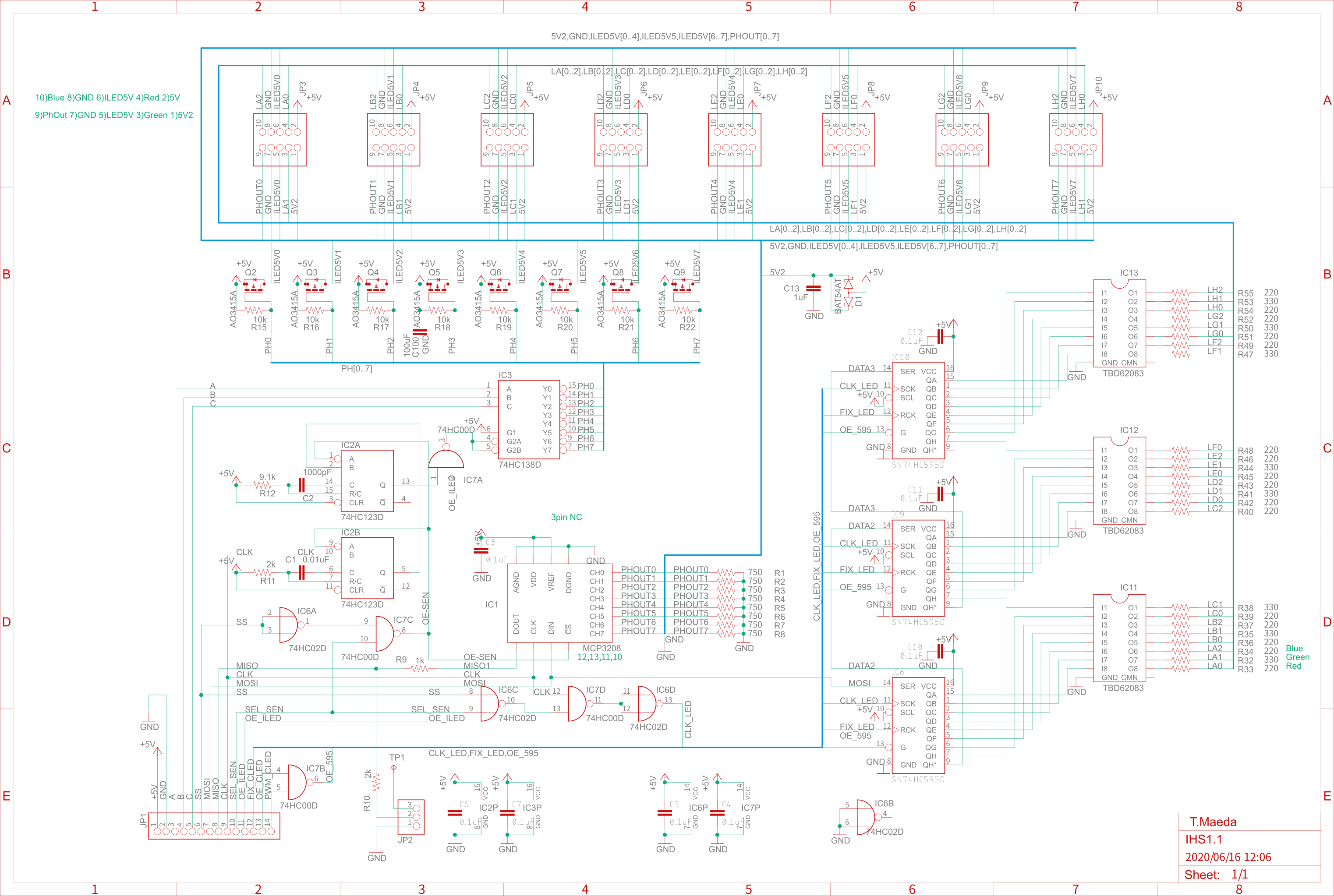
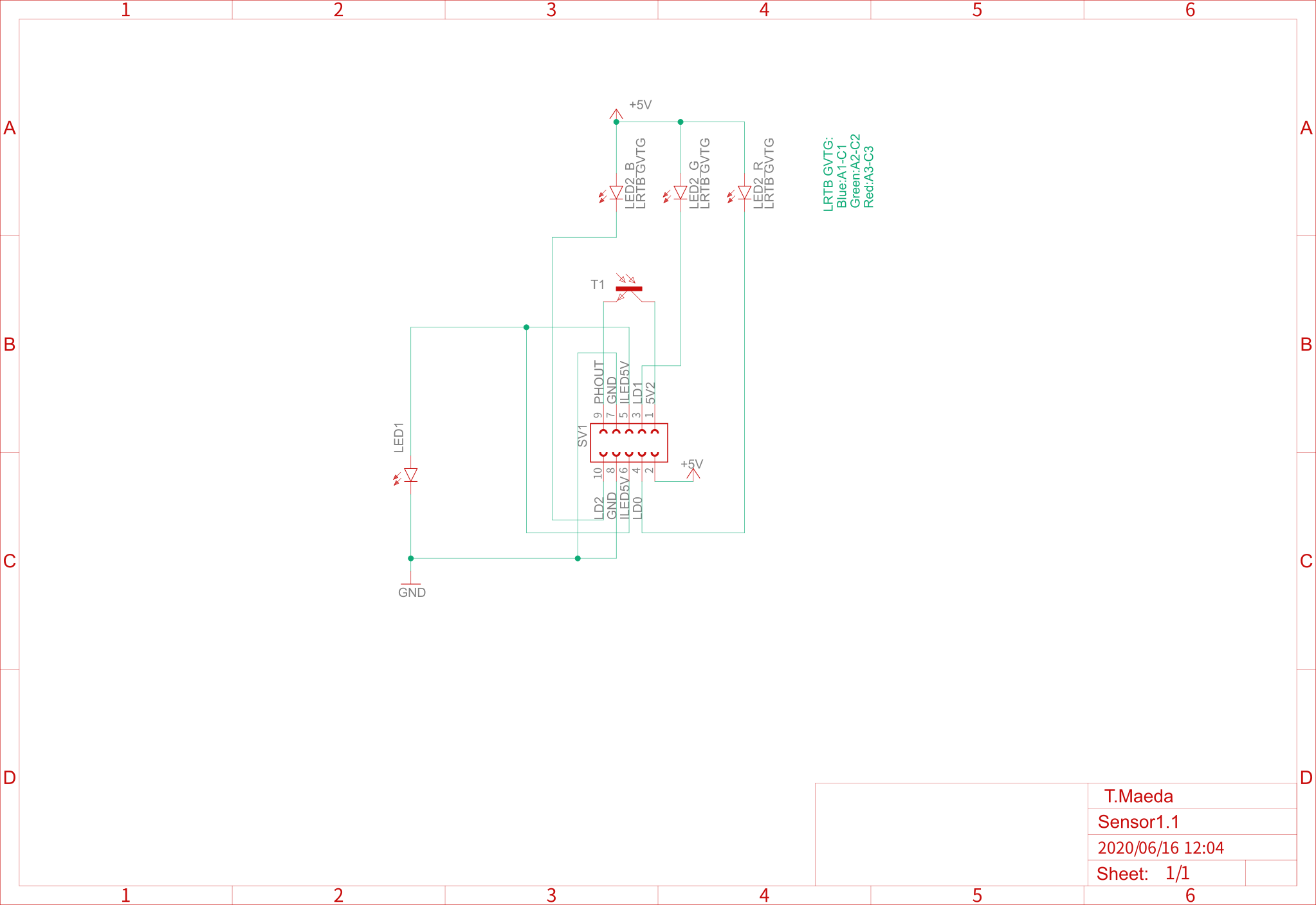
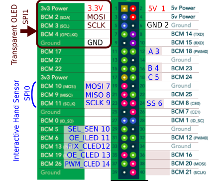
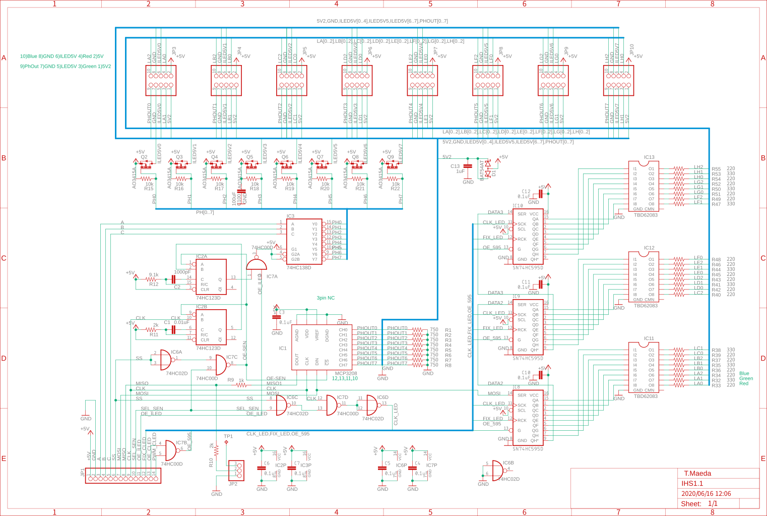
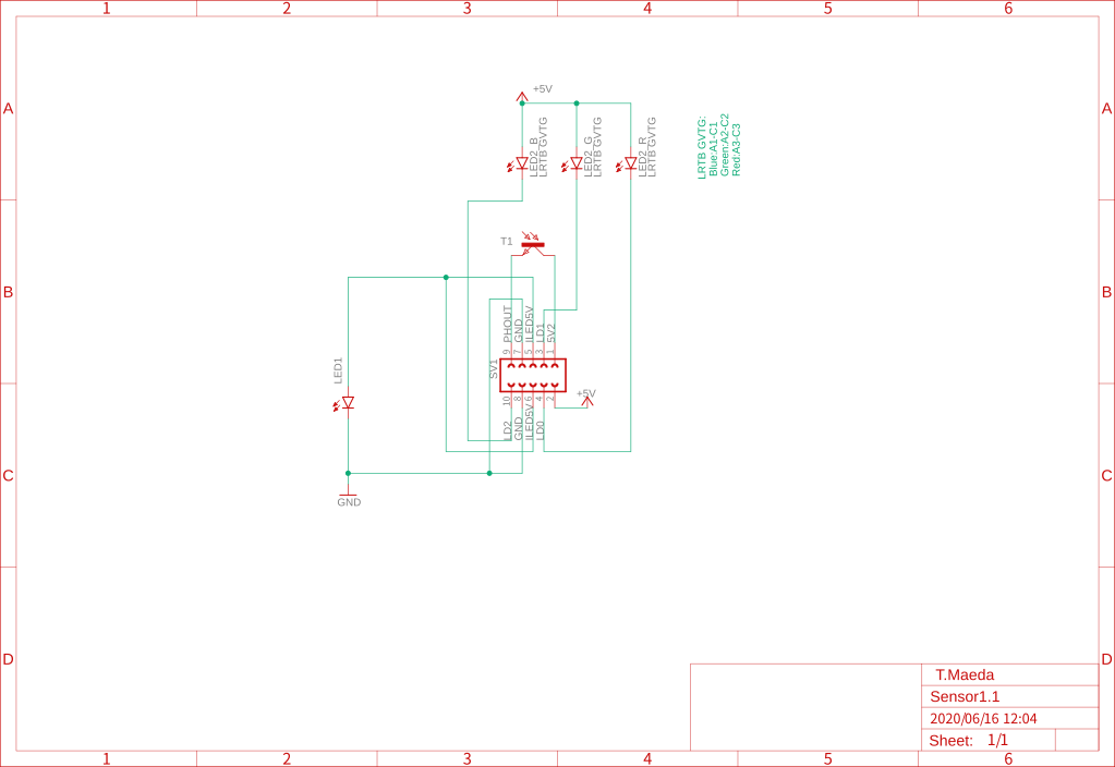
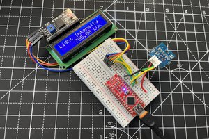
Circuit diagram
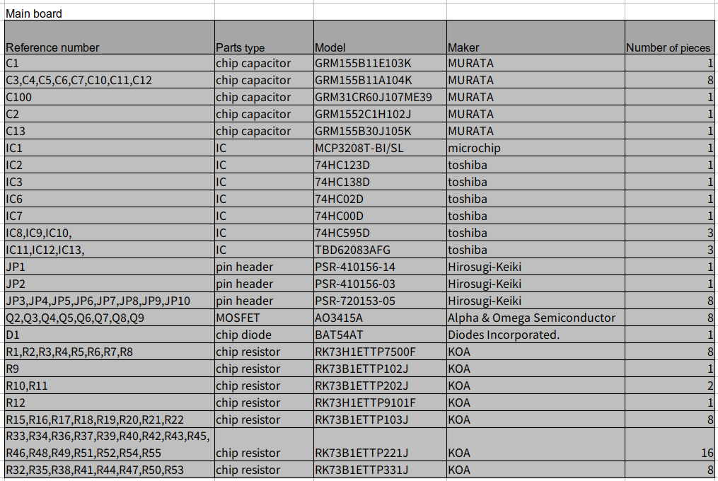
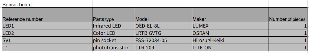
Parts list
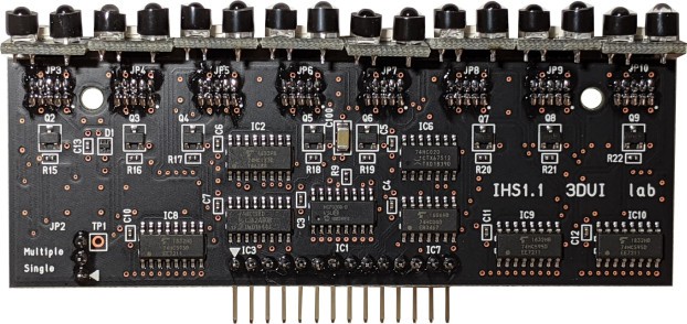
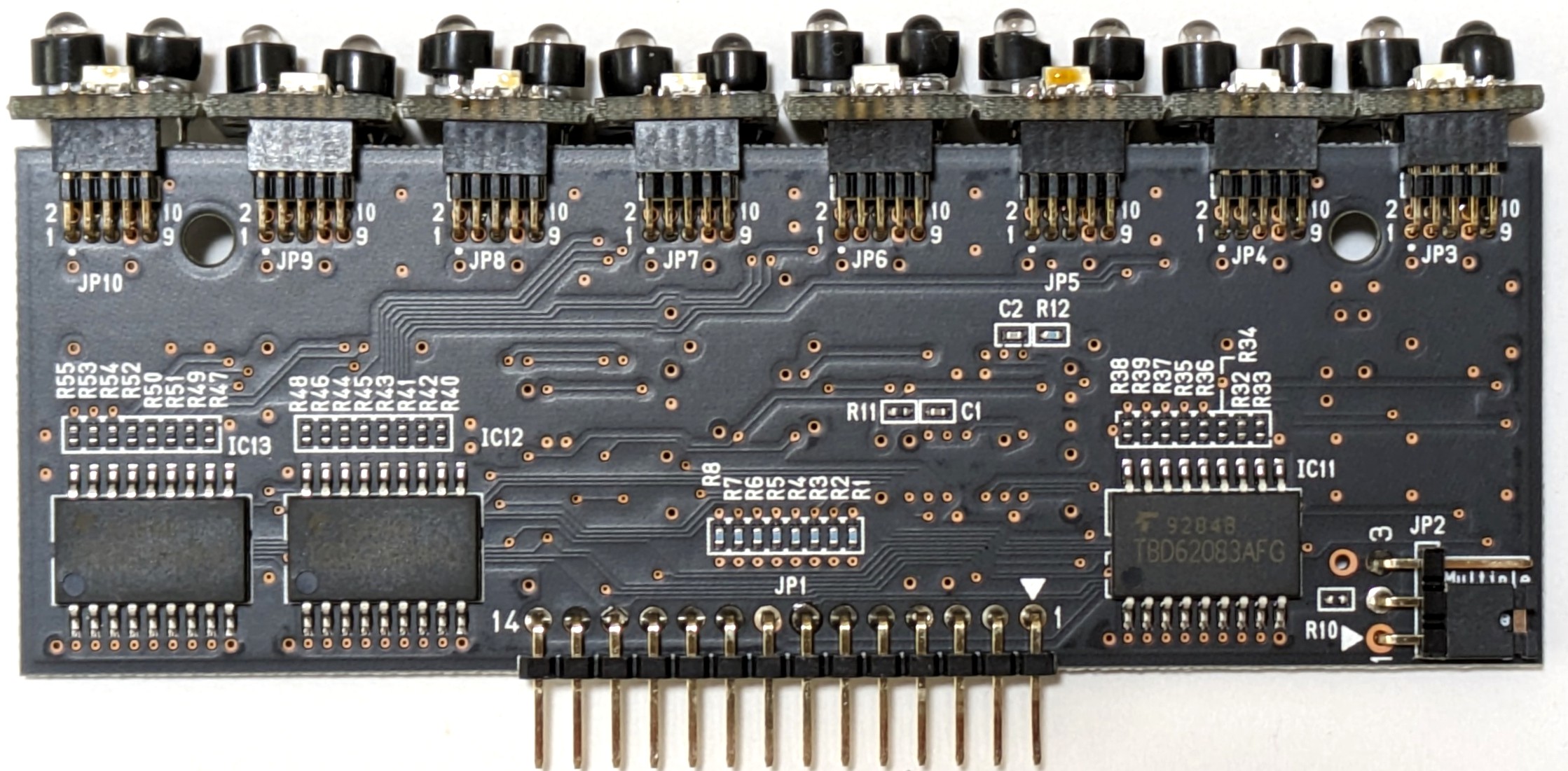
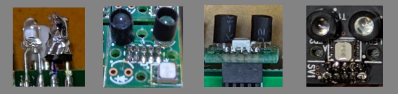
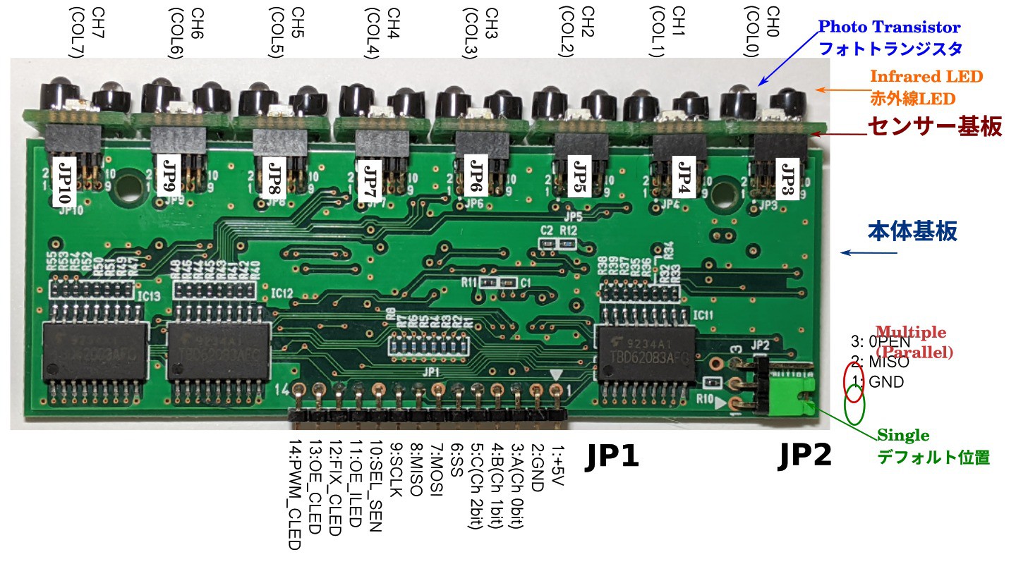
Photo
Logic analyzer
The process rules for semiconductors are getting smaller every year, and the accuracy is improving, making it more difficult to break.
Recent semiconductors have a gray zone of about 100 microseconds. In the gray zone range, even if the current exceeds the absolute maximum rating, it will not be damaged.
The sensor has been tested continuously for more than 2 years and 2 months with no problems.
It is on salein Japan.
Non-contact touch panel
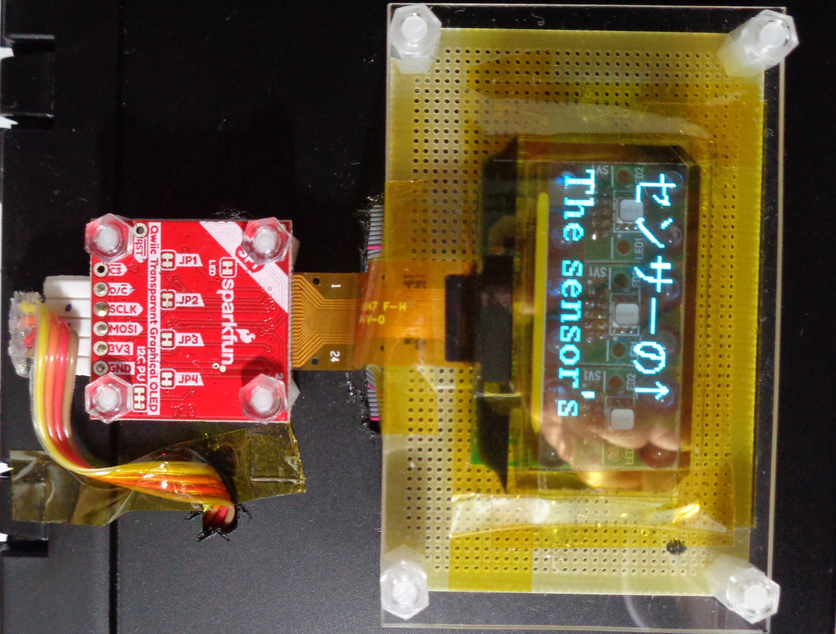
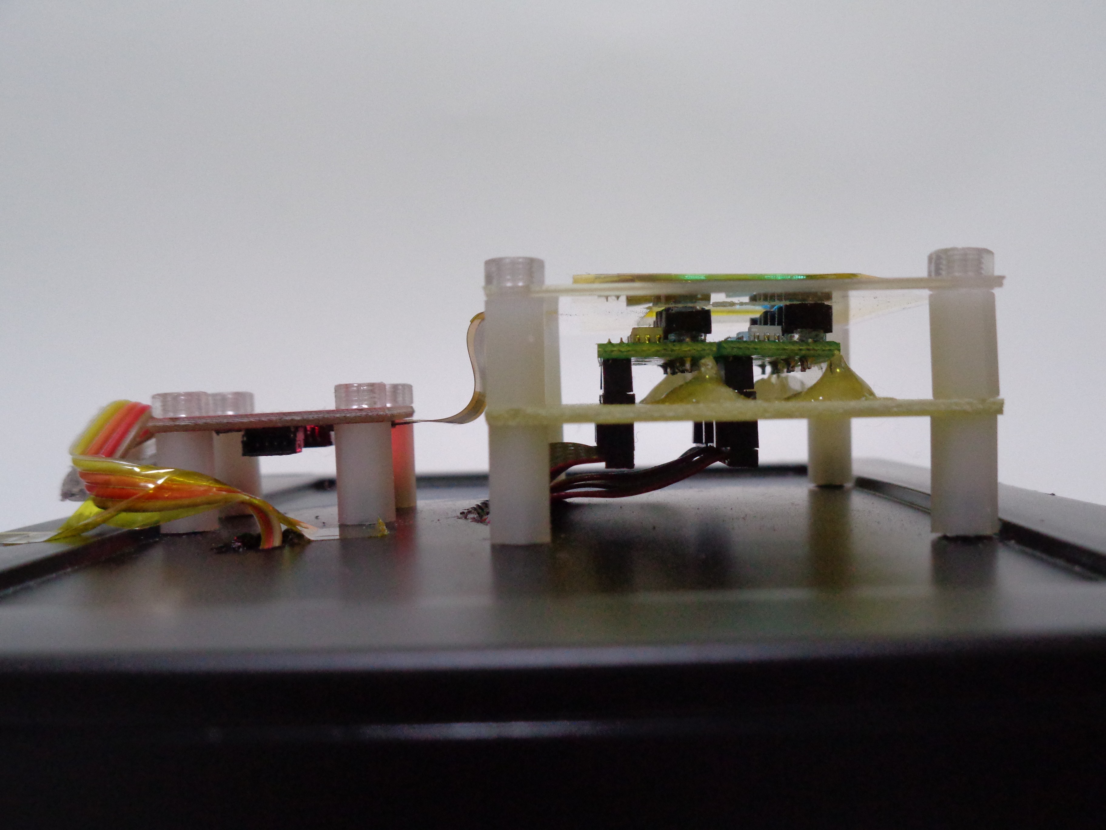
The sensor's infrared rays can pass through the transparent OLED panel to detect fingertips.
A non-contact touch panel made with this
I think it will help prevent infectious diseases when used at airports and ports around the world.
Only available at 1.51 inches with a smaller transparent OLED display.
Since only 6 sensors can be used, it is easily affected by momentary optical noise and is prone to false detection. So the software has a special way.
In the loop, the number of times the hand has entered the sky above the display is counted and the direction with the largest number of times is acquired. This gives about 95% correct detection.
If a non-contact touch panel is commercialized, the sensor can be deployed in a wider range, so the direction should be taken accurately.
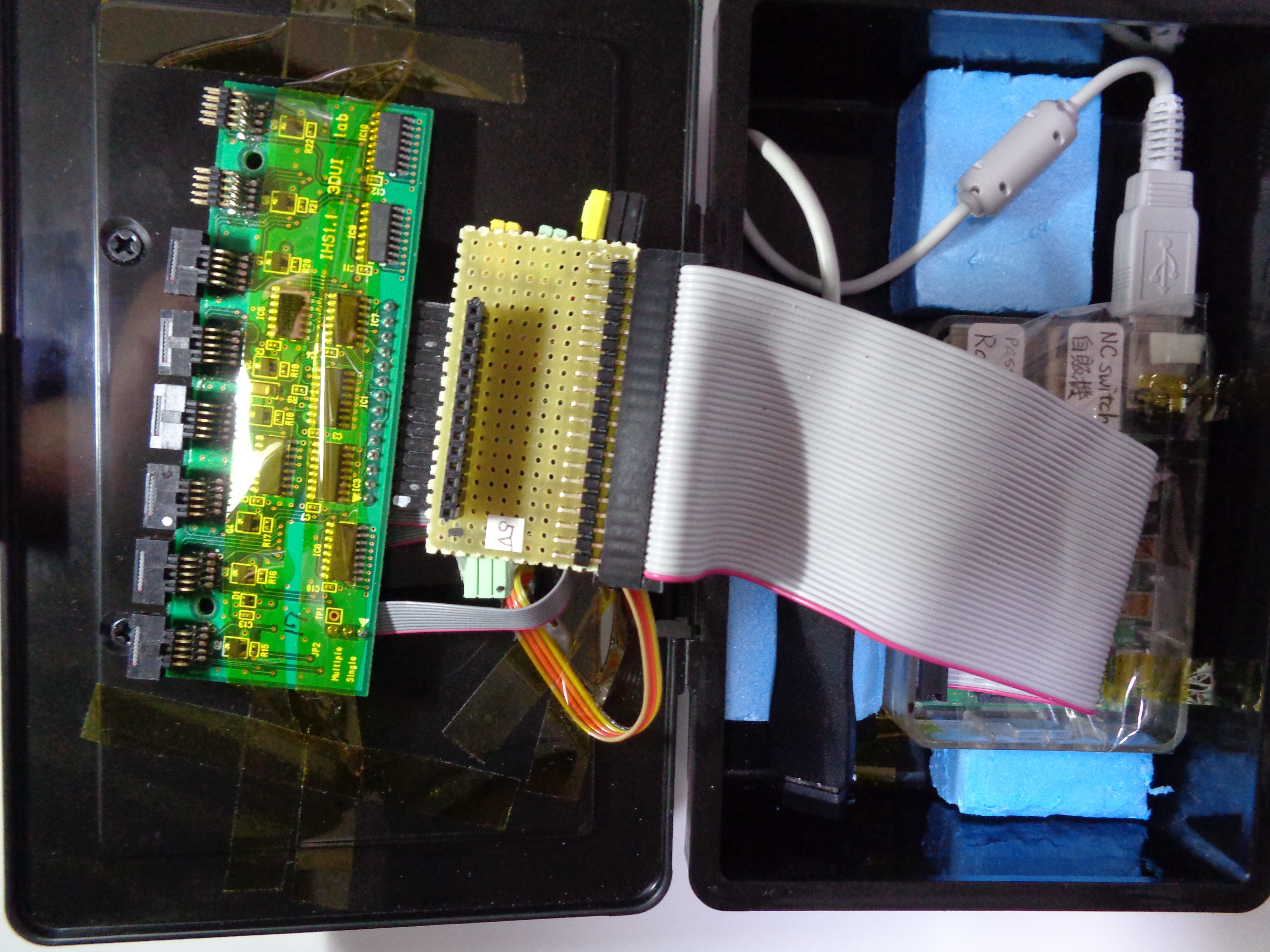
Software is Python on Raspberry pi 4, using the luma.core library
https://github.com/rm-hull/luma.core/blob/master/LICENSE.rst


 ElectroBoy
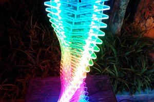
 Est
Est
 Blecky
 Minimum Effective Dose