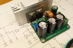
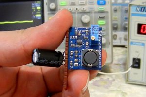
DC-to-DC buck converters are utilized ubiquitously in electronic devices. Three major types of non-isolated DC-to-DC converters are introduced: Buck, Boost, and Buck-Boost. The most frequently employed type is the Buck converter. In this article/video, I introduce a compact buck converter board, capable of accepting input voltages ranging from 8V to 95V and handling 5V-1A at the output.
The selected controlling chip is the MP9486. It is a high-frequency and somewhat sensitive controller chip as some users reported encountering instability issues. However, I have applied a few modifications to the circuit and as a result, you can utilize this circuit, PCB, or assembled board without any issues. The circuit offers consistent regulation within the defined input voltage range, effectively managing the maximum output current.
For the schematic and PCB design, I utilized Altium Designer 23. I shared the project with my colleague for feedback and edits through Altium 365's secure cloud space. The Octopart component search engine proved invaluable for obtaining component information and generating the Bill of Materials (BOM). To ensure the production of high-quality fabricated boards, I forwarded the Gerber files to PCBWay.
I tested the circuit's performance for a range of input voltage, output current, stability, and output noise. This comprehensive testing was conducted using the Siglent SDL1020X-E DC Load, the SDM3045M multimeter, and the SDS2102X Plus oscilloscope.
I am confident that this circuit fulfills your requirements for a compact high-voltage buck converter board.
 hesam.moshiri


 GreenPAK™