 Dominik Meffert

Over the last months, I did some testing with different printhead designs, self-mixed inks, and some new parts and features for improving the reliability of the printer, to prevent frustration while testing.
Great thanks again to @Paulo Campos for helping me with that.
There were two main problems I tried to solve with the improvements:
- Clogging of the nozzle
- Electrode output leaking to ground due to ink/dirt forming a conductive path to ground on the isolators.
Both errors prevent the printer from working, so it's best to prevent them or solve them quickly when they appear.
Maybe I will later add a feature to the printer to detect (and maybe even solve) them when they appear while the printer is printing.
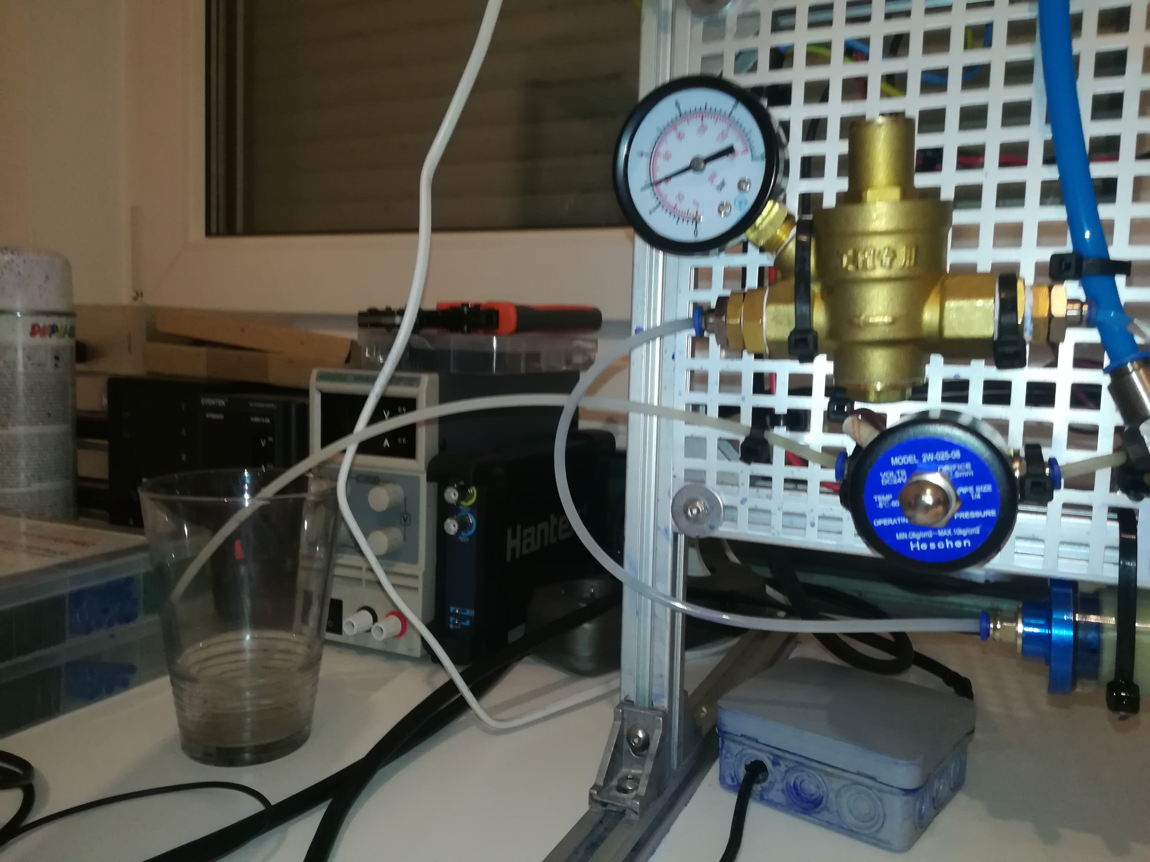
I also improved another problem that caused a rise in ink pressure while reloading the timer chamber by adding a water pressure regulator to the ink line.
This rise led to a shifting of the ink stream break-up point and could shift the break-up point out of the charge electrode which would prevent the printer from working.
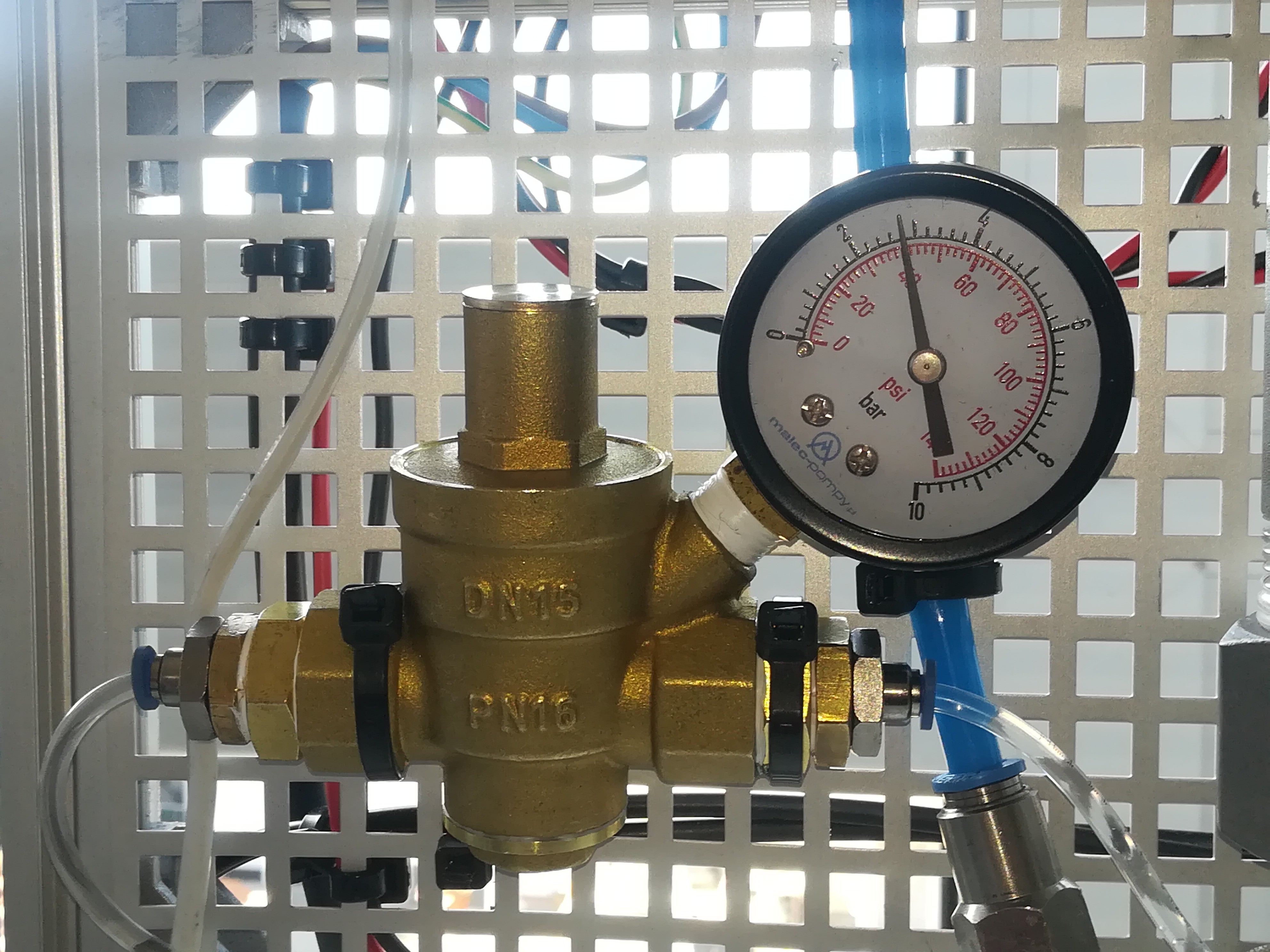
Adding a water pressure regulator reduced the reloading rise from about 10psi to 1psi which I think should be OK for now.
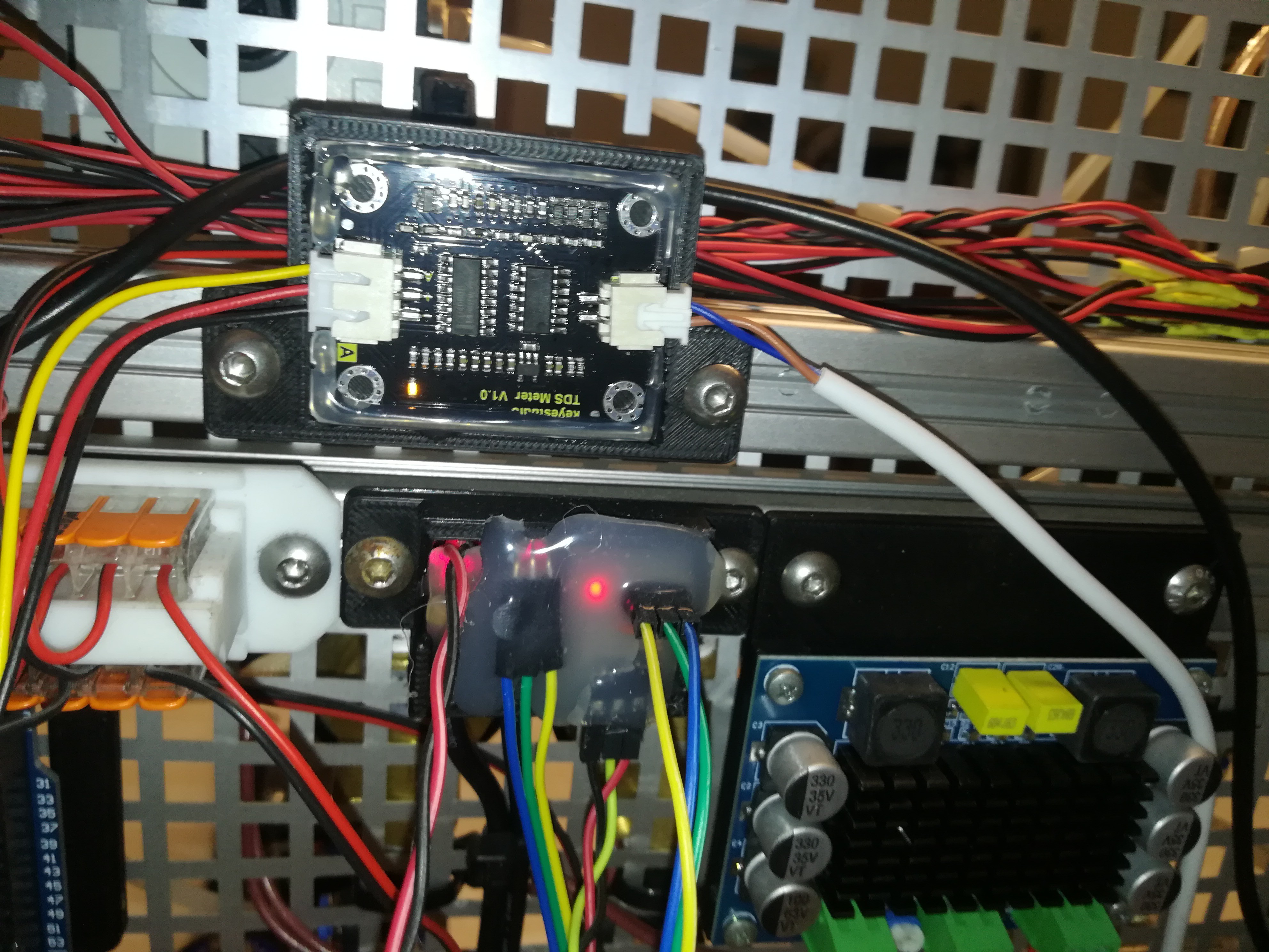
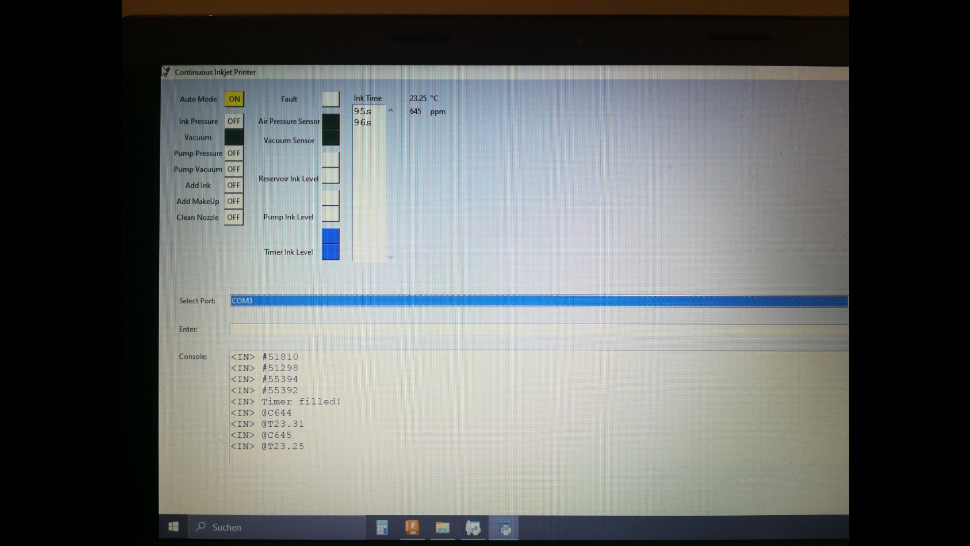
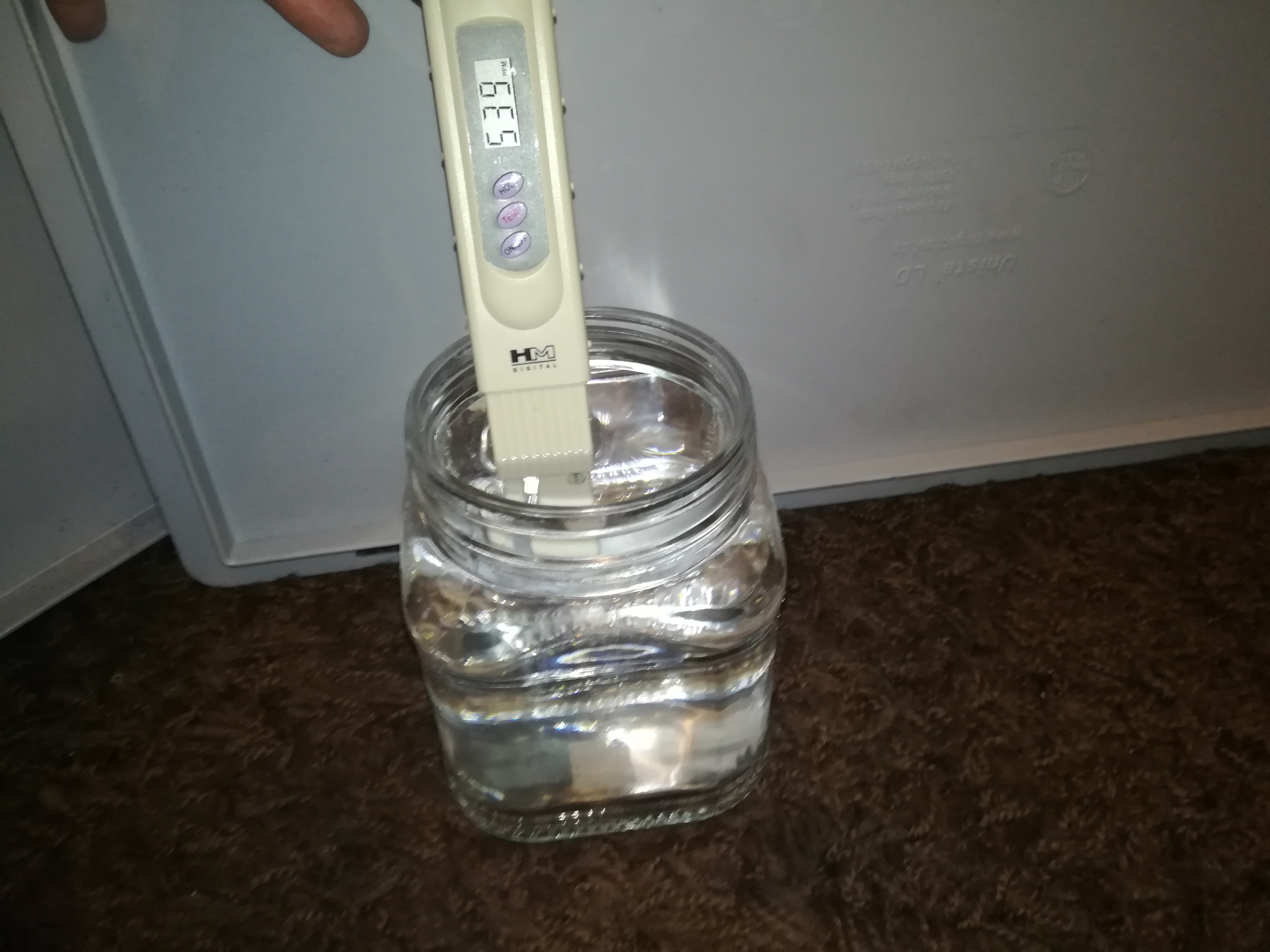
For getting more info about the ink in the system I added a temperature and a TDS sensor to the printer. It's important for the printer's operation to keep the ink at the right conductivity and viscosity.
With the TDS sensor and timer, it's possible to keep an eye on these values.
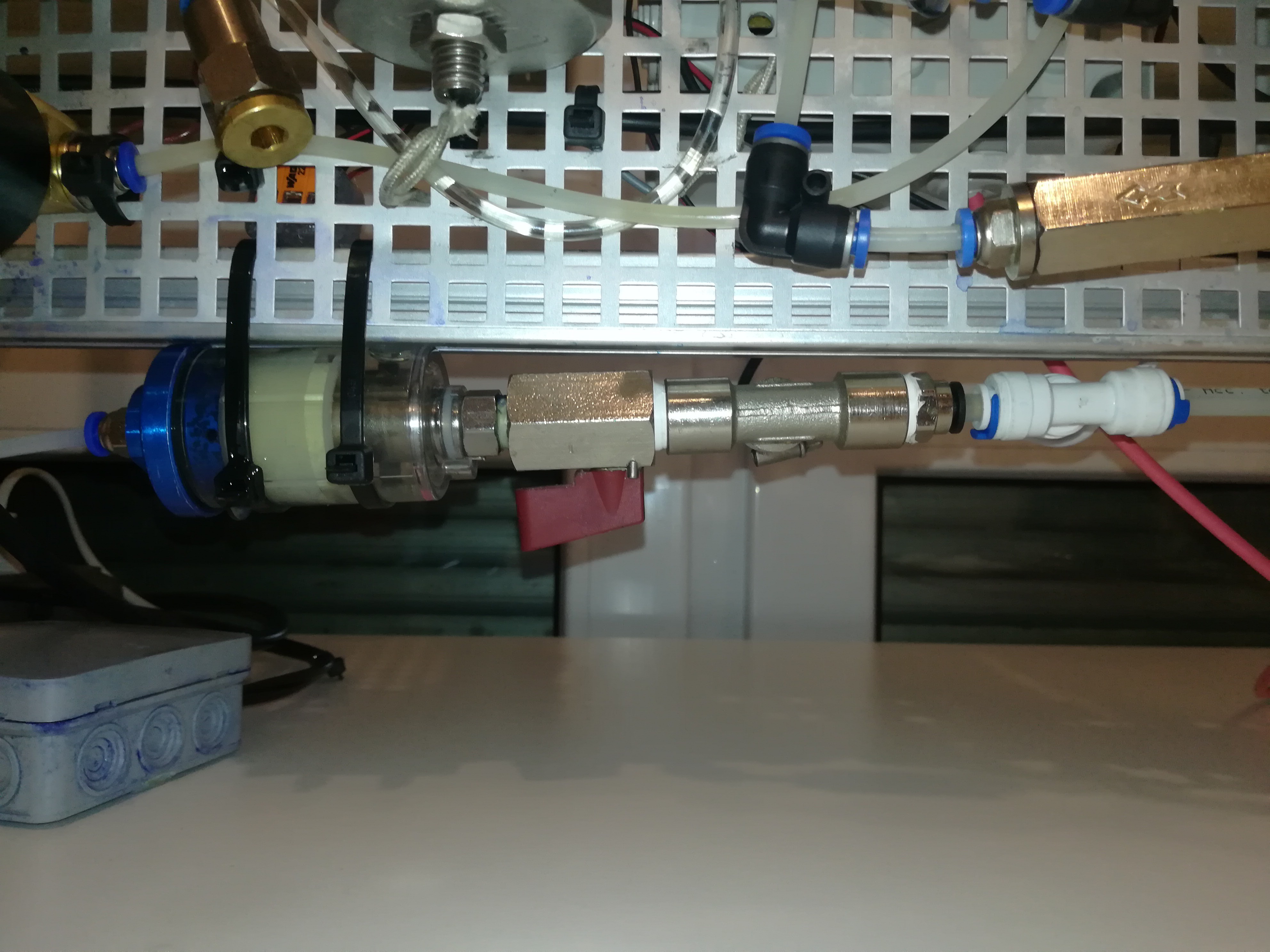
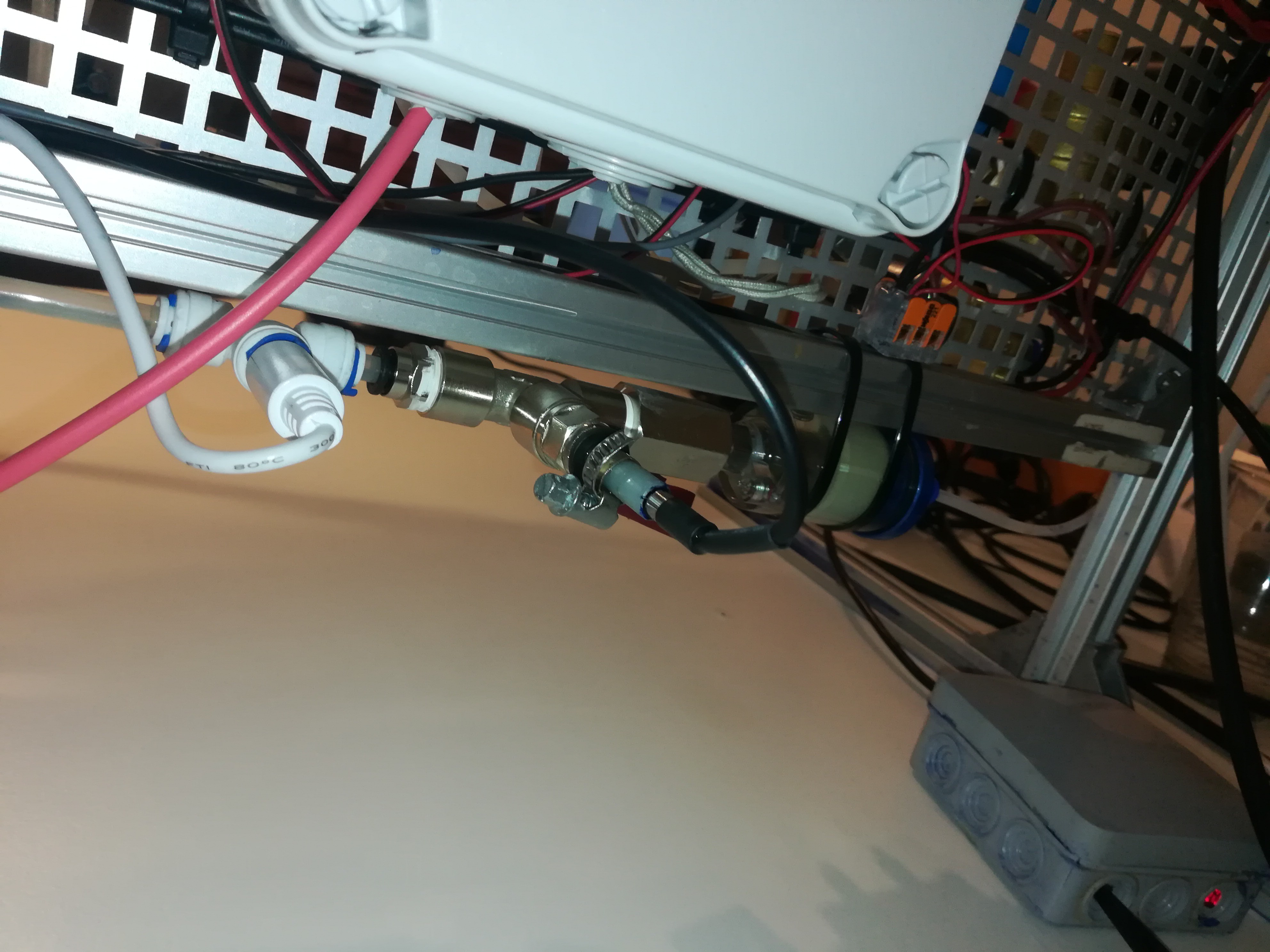
In the future, I want to mount the printhead on a moving carriage for labeling and 3D printing. While the printhead moves and the feed lines bend back and forth the ink pressure would float which could affect the operation and printing quality. To prevent this, I added a small spring-loaded puffer/damper to the ink line that should later act like a capacitor for keeping the ink pressure constant.
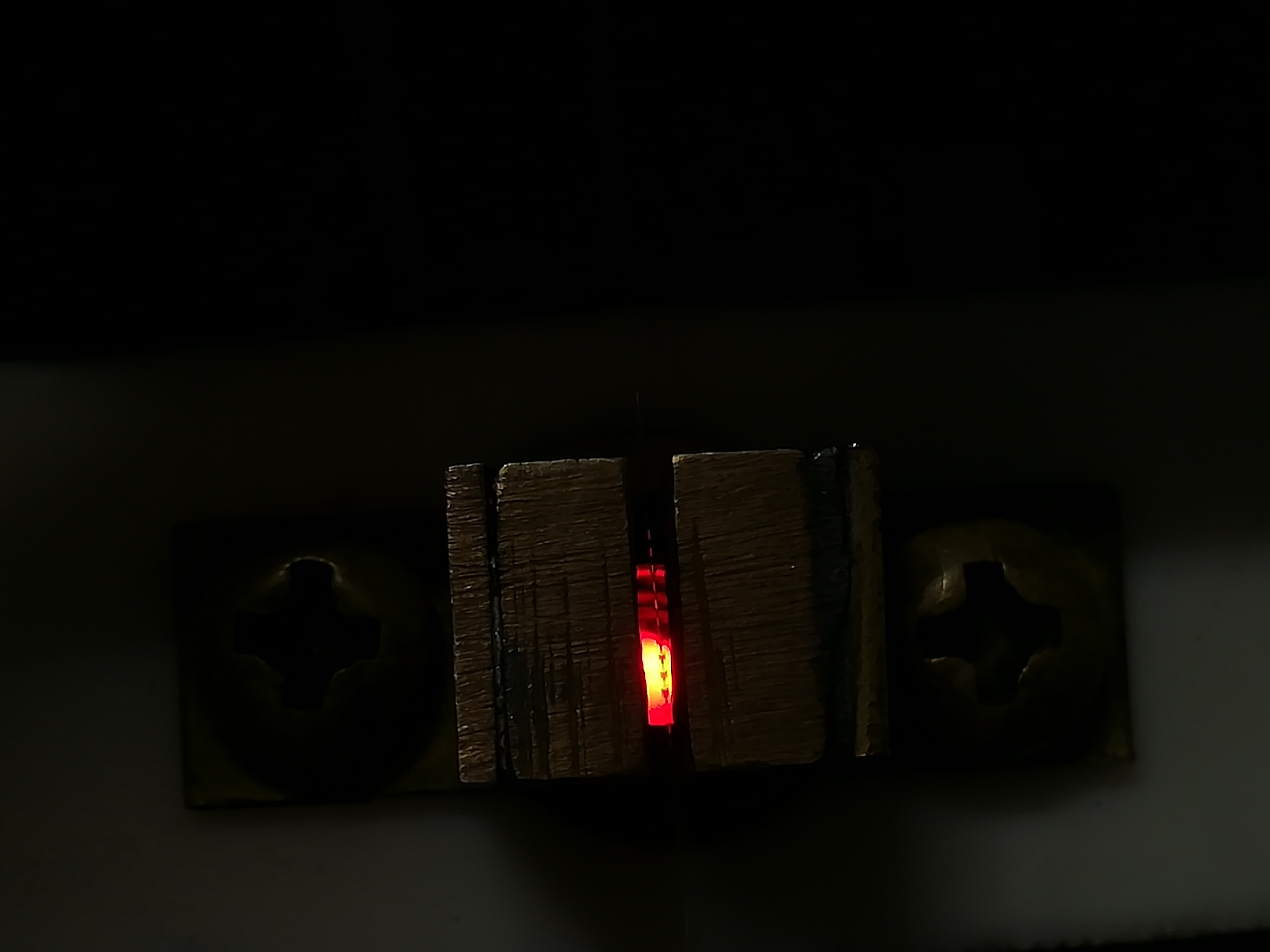
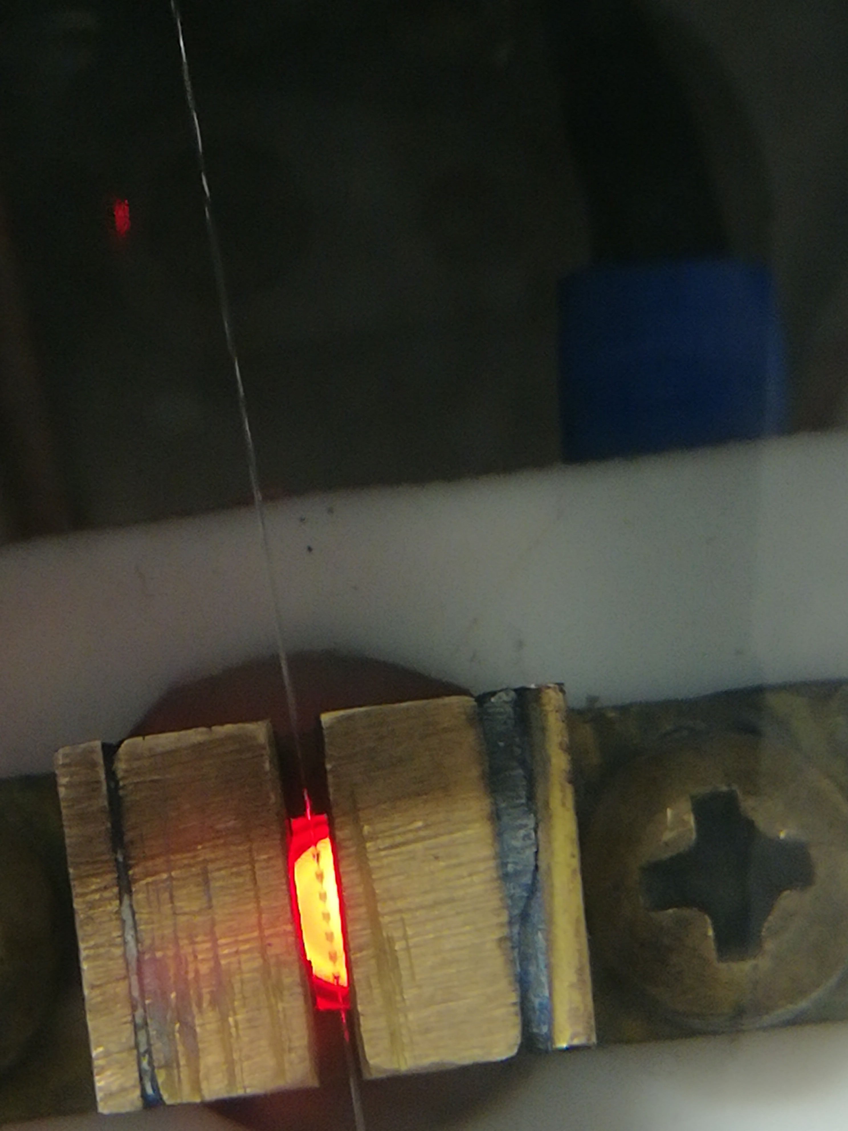
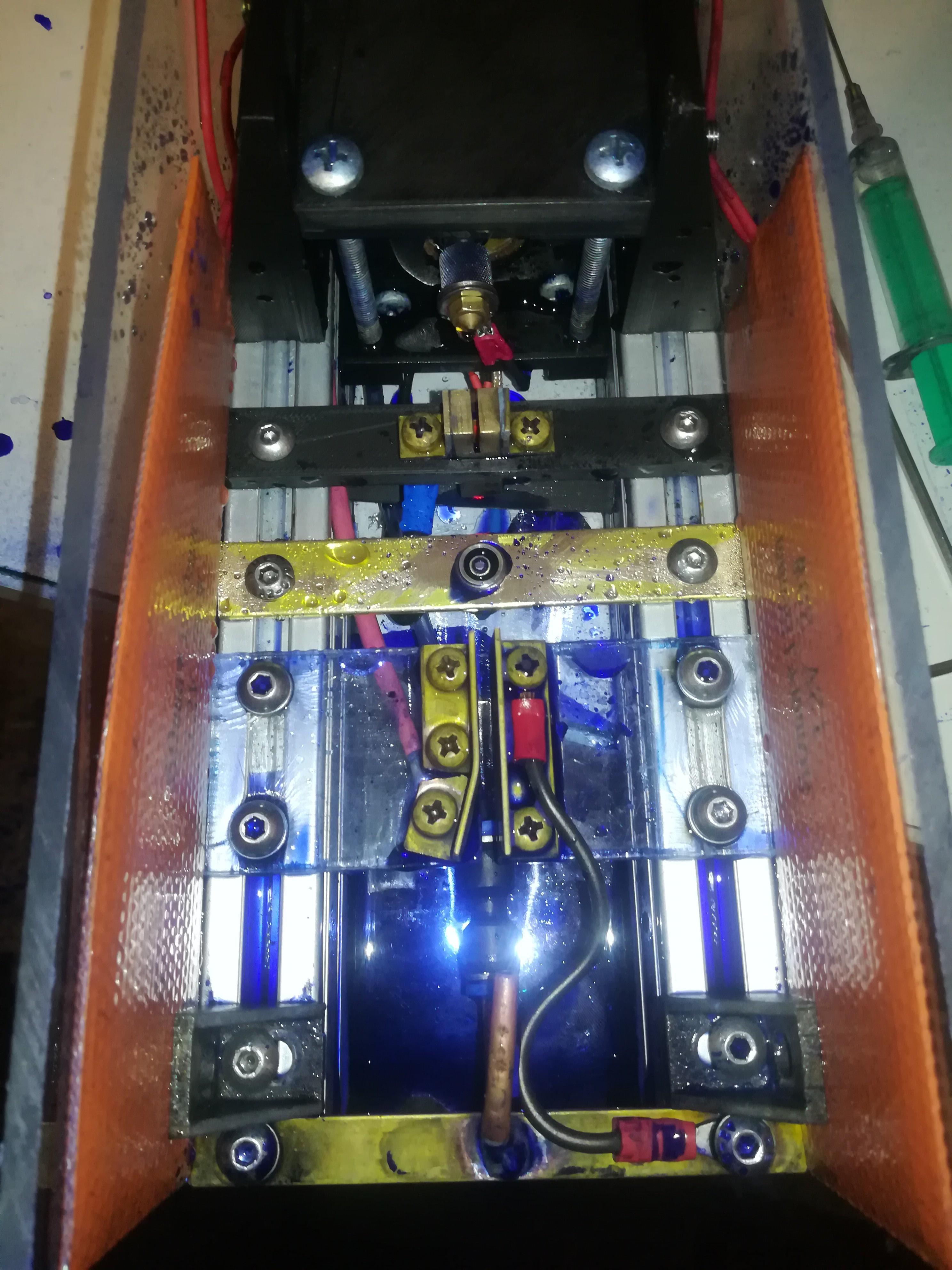
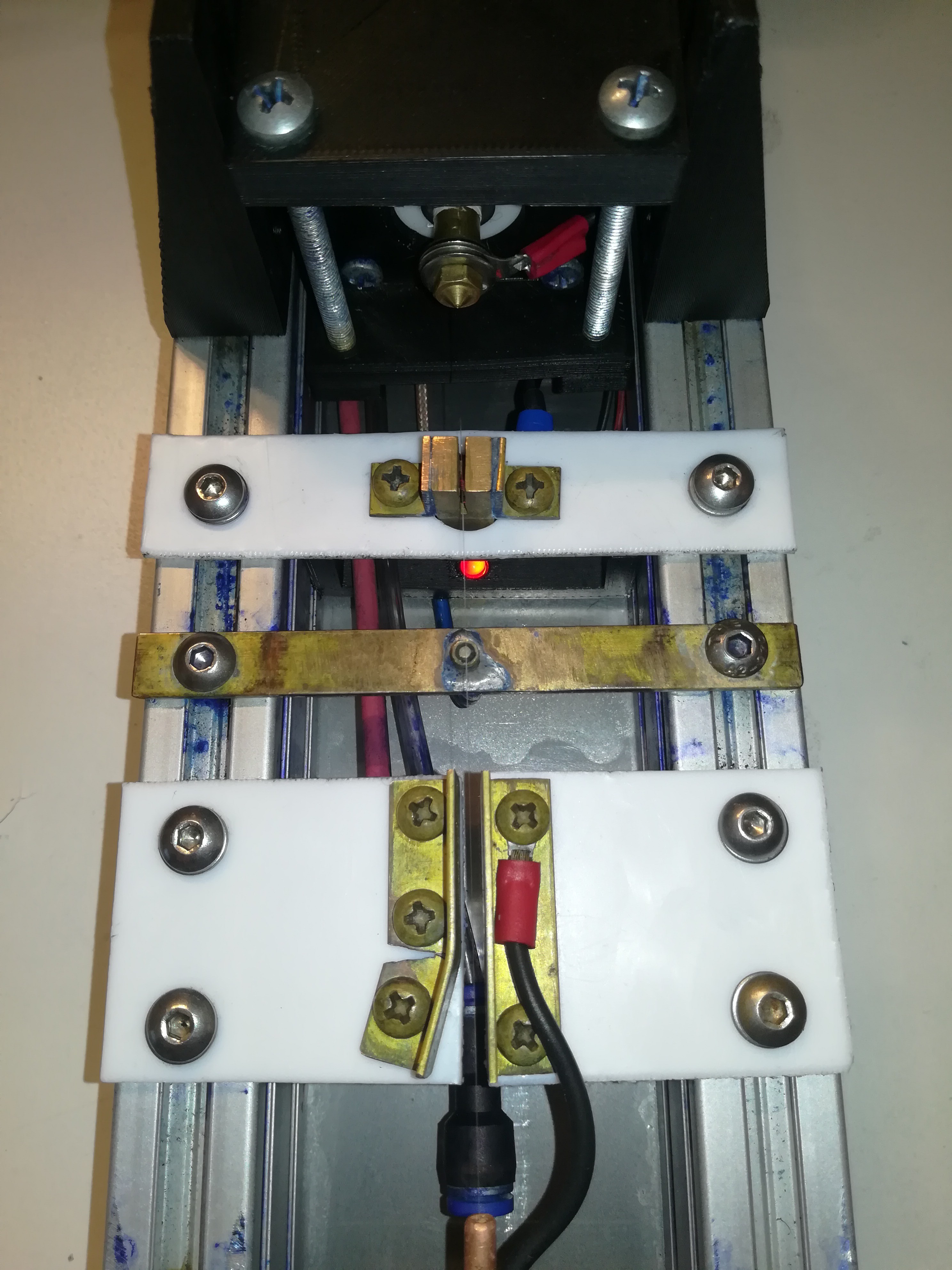
To make the observation of the ink stream break-up and droplet-formation easier, I replaced the white LED with a red LED.
The Output to Ground Leakage Problem:
In the past, I did a lot of testing with water-based inks, because water is safe to use and not flammable.
A major drawback of water is that it takes a long time to evaporate.
That leads to a lot of problems with it like:
- Corrosion on places where conductive water reaches in, but does not dry for a really long time like on the aluminum coated piezo ring or underside of aluminum profiles.
- Water puddles from ink stream alignment or dealing with a clogged nozzle. Because the water takes very long to dry, the ink can collect on the printhead, desktop, and floor even if only a small amount of ink misses the gutter or hits an electrode. With water, this leads really quickly to puddles that would otherwise just evaporate after a few seconds.
- Output to ground leakage caused by small amounts of conductive water settle in small scratches from cutting at the edges of the isolators, which renders the electrodes unusable for a long period of time after each splashing with test ink - what happens very often while testing.
This made testing in the past as good as impossible.
In the end, I came to the conclusion that the fire hazard of fast-drying liquids like ethanol is easier to handle with the right safety precautions than the problems caused by slow-drying water.
In the industry, most CIJ printers also use fast-drying ketone or alcohol-based inks.
And so I switched to ethanol-based ink.
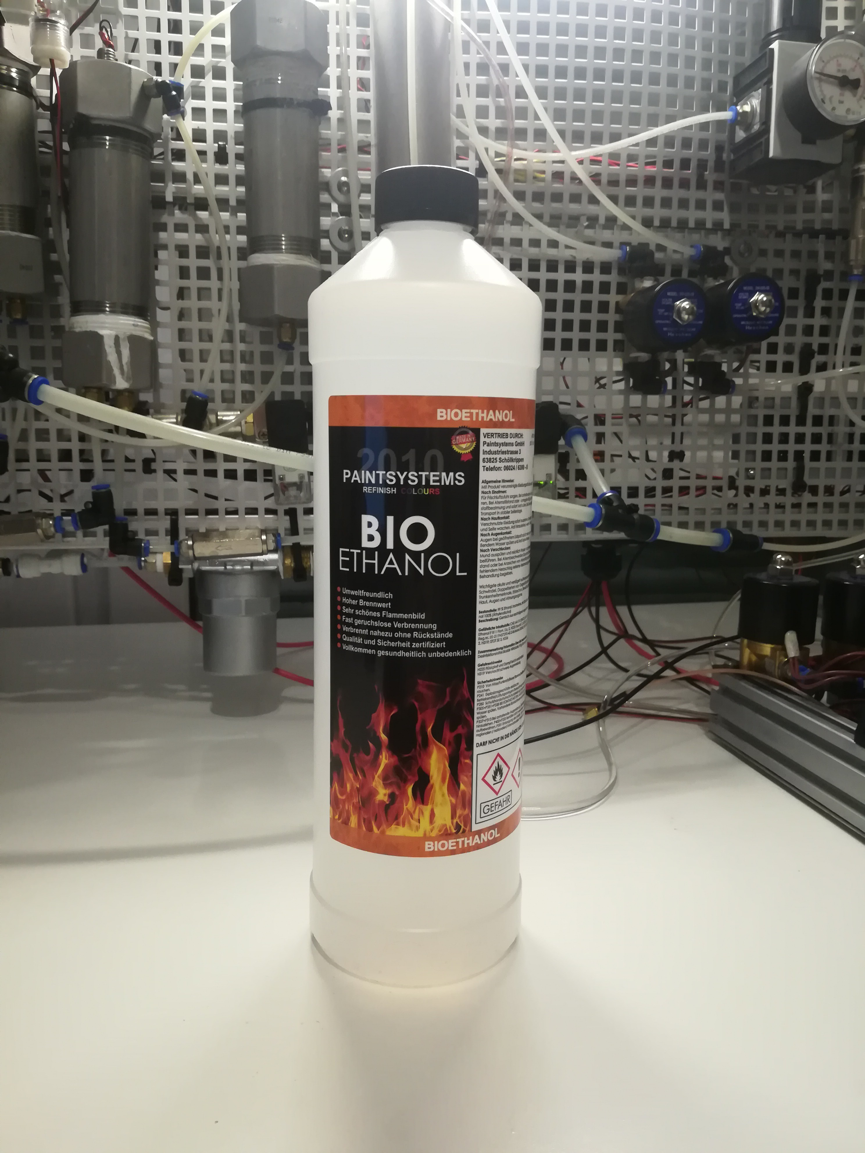
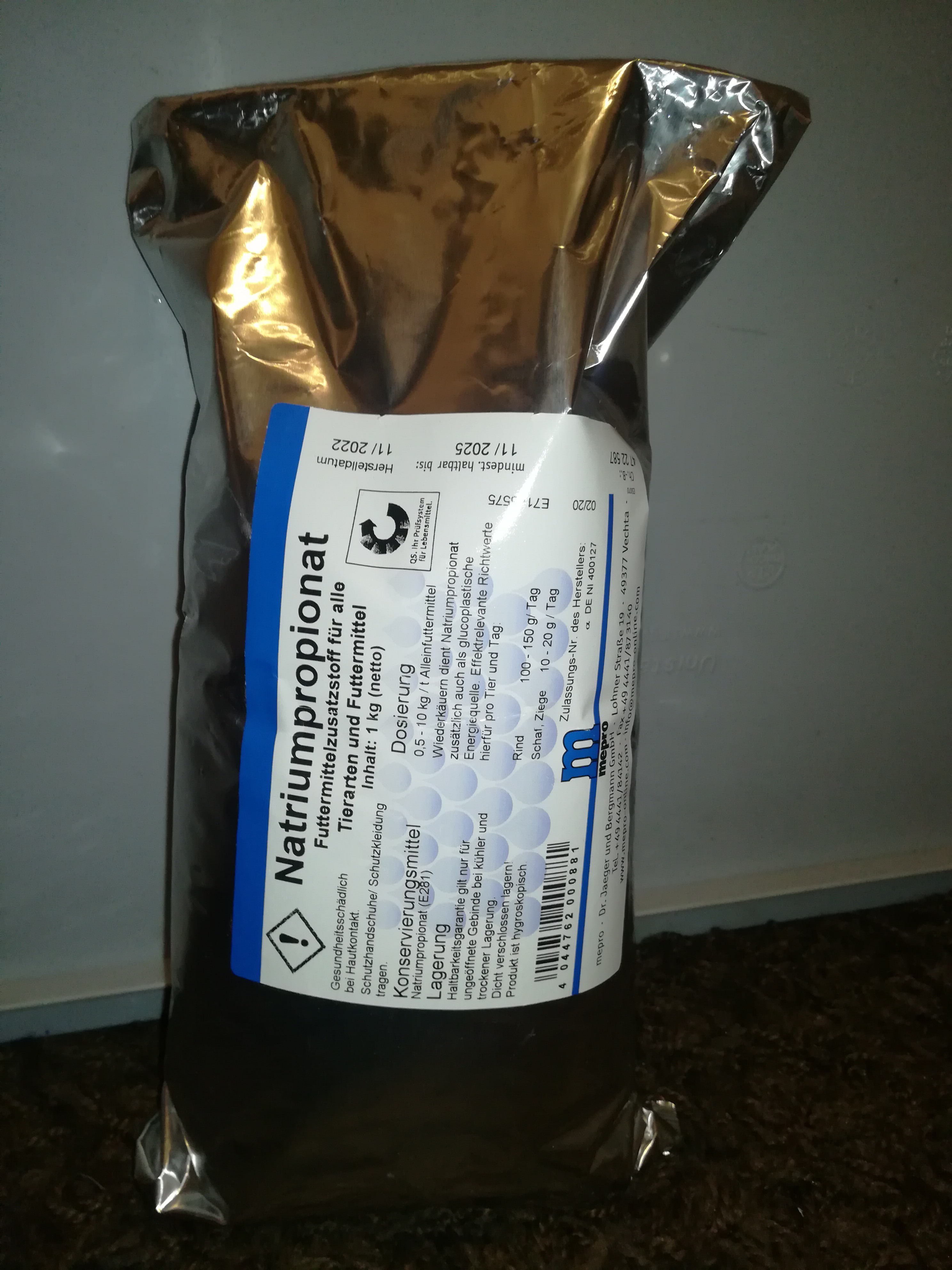
Today, I received a bag of sodium propionate which contrary to sodium chloride and sodium carbonate (which I used before with water) dissolves well enough in ethanol to increase the conductivity to the needed level without the need to add water to the mix.
With ethanol, the situation really improved. When some ethanol got spilled on the printhead, table, or floor it could be wiped off and the residue on the surface evaporated completely after just a few seconds.
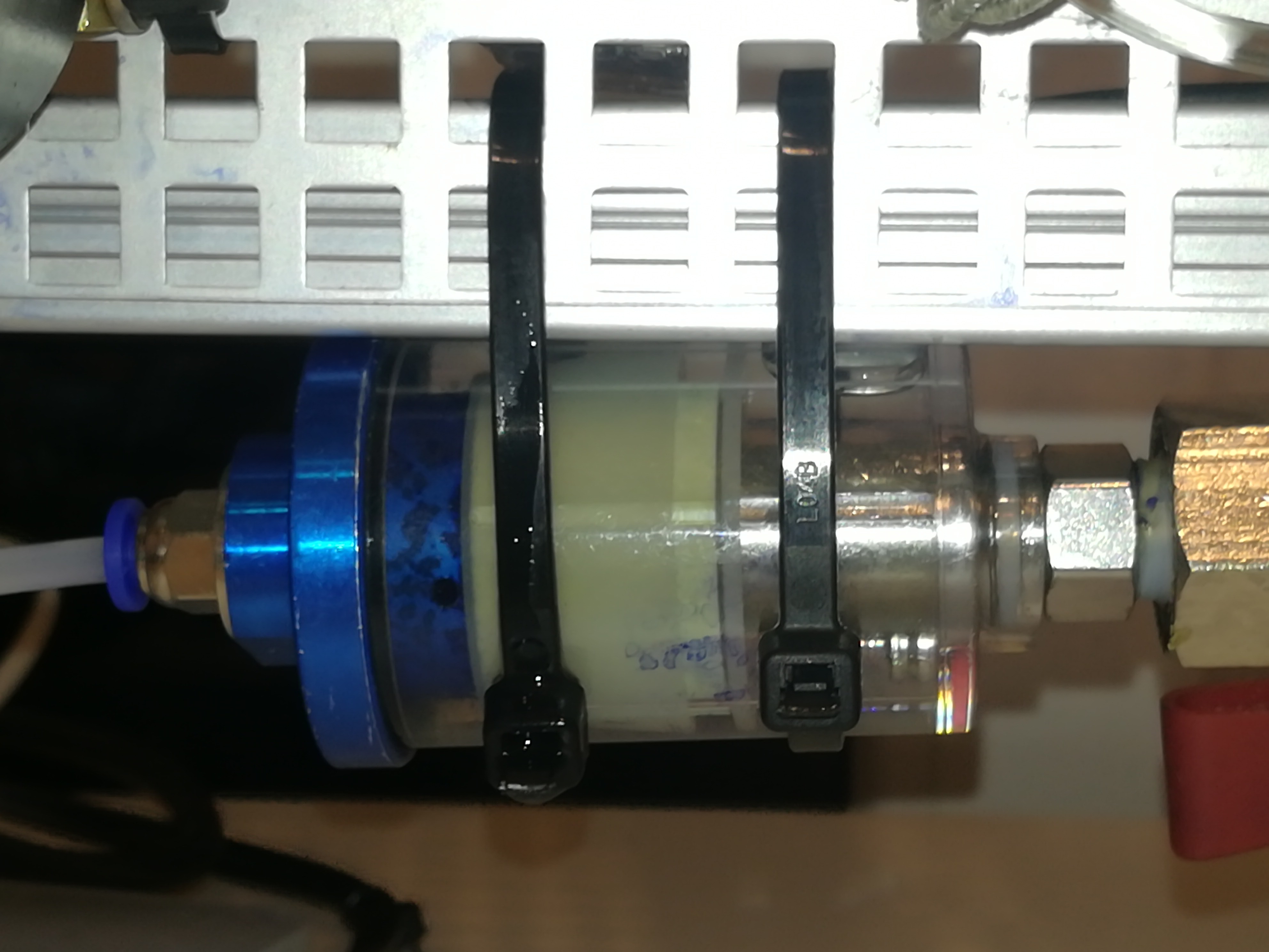
Some parts of the printer like the ink filter, piezo mount, and polystyrene parts were not compatible with ethanol, so I had to replace them.

On the printhead, I tried different materials for the isolators. While using the water ink I used polystyrene isolators and 3D printed isolators, but because the water settled in every small scratch and also soaked between the layers of 3D printed parts it did not work very well - the smooth polystyrene worked better for water than the 3D printed parts.
For ethanol, polystyrene is not suitable because it gets dissolved by it over time. 3D printed parts work better than with water but the ethanol also creeps between the layers and stays there longer.
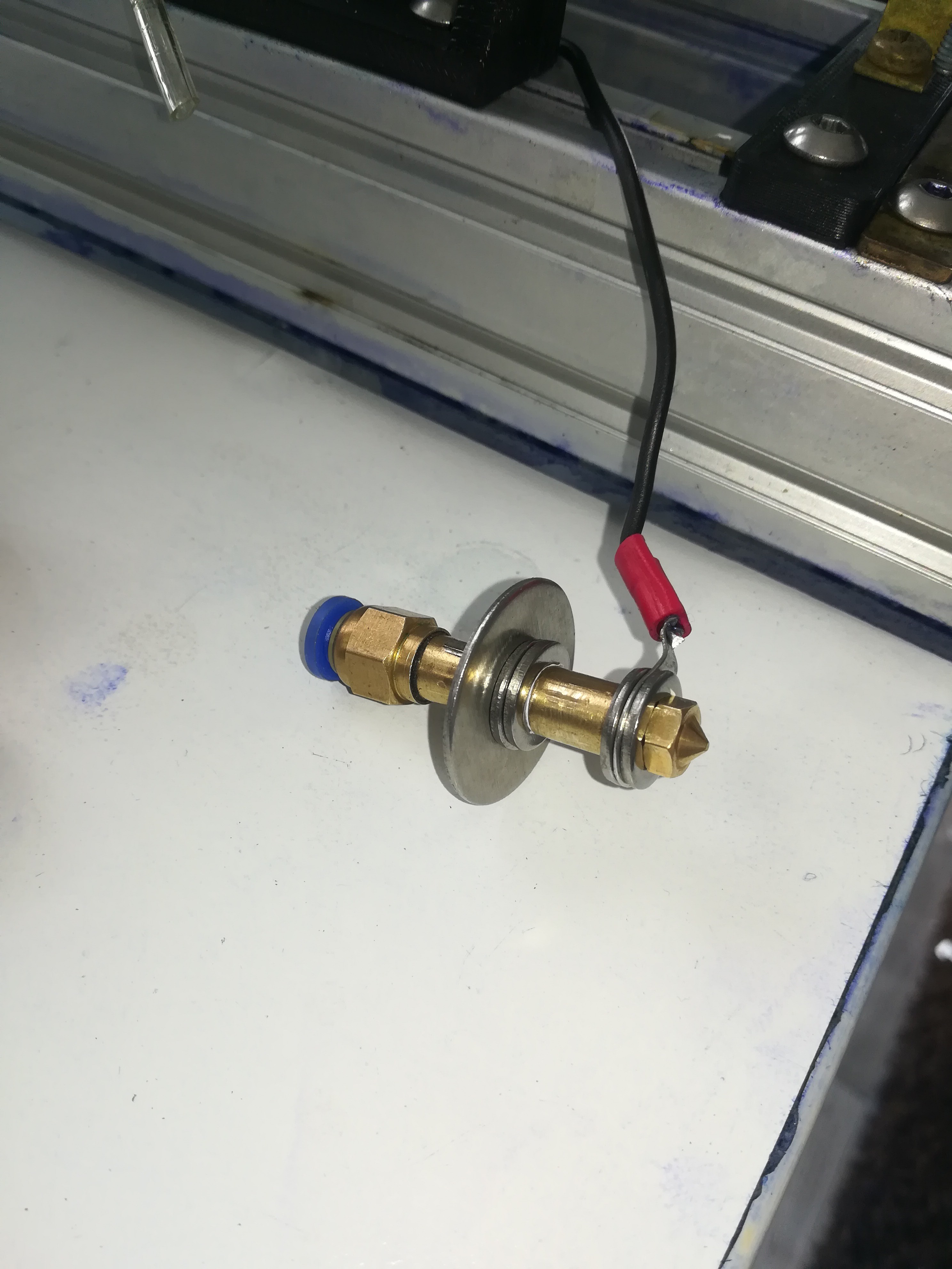
In the end, I had the idea to use PTFE for the isolators which has a high chemical resistance and also a liquid and dirt-repelling surface which is very nice for keeping the isolators dirt free to prevent forming of conductive paths to ground on the isolator's surface.
I did some testing of the high-voltage electrode:
I measured the high voltage which I set to 3,33kV. Then I sprayed the isolator with ethanol which led to the measured voltage dropping to around 100V. Then I wiped the top and bottom of the isolator with a paper towel and blew some air on the isolator to let the residue evaporate. I measured the voltage again and measured 2,95kV which over the next seconds rose back to 3,33kV.
It seems like, from all tested materials PTFE worked the best so far.
I think that the ground leakage problem is solved for now and I can finally start testing with the electrodes. And in case of an isolator gets splashed with ink, the ink will dry off pretty quickly so that the testing can be continued after just a few seconds.
The Nozzle Clogging Problem:
Before the last change nozzle clogging was a serious problem. When some dirt or PTFE flake from sealing PTFE tape reached the nozzle, it obscured the ink stream which prevented drop break-up from happening, changed the break-up point position, or led to a non-straight ink stream that hit an electrode, missed the gutter or shoot across the room.
Sometimes it helped to wipe the nozzle tip with a finger to unclog the nozzle, but often it was needed to disassemble the nozzle assembly and clean or replace the nozzle.
So I added a nozzle cleaning feature to the printer, that connects the nozzle to the primary vacuum line if activated.
This way the nozzle can be flushed and dirt can be disposed of into the vacuum puffer chamber. While doing so any flushing solution can be used because unlike the normal ink, the dirt and flushing solution doesn't get recycled in the system and so they can not contaminate the ink in the system.
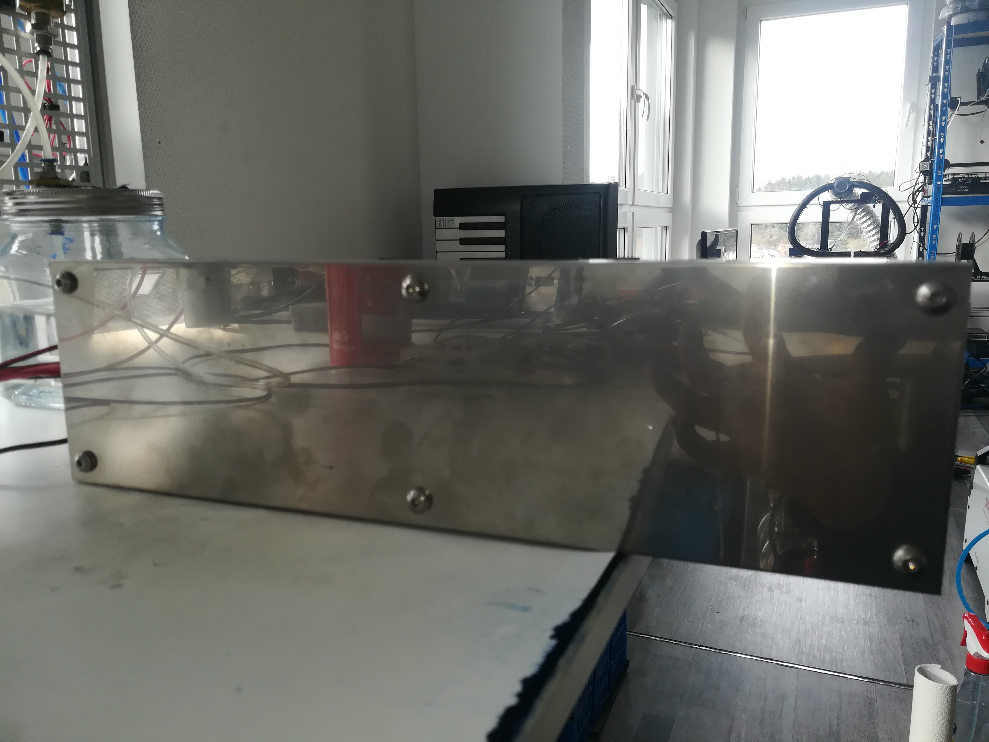
The cleaning function is turned on by the two valves on the back of the printer. The left one is used for the ink and the right one is used for the vacuum.
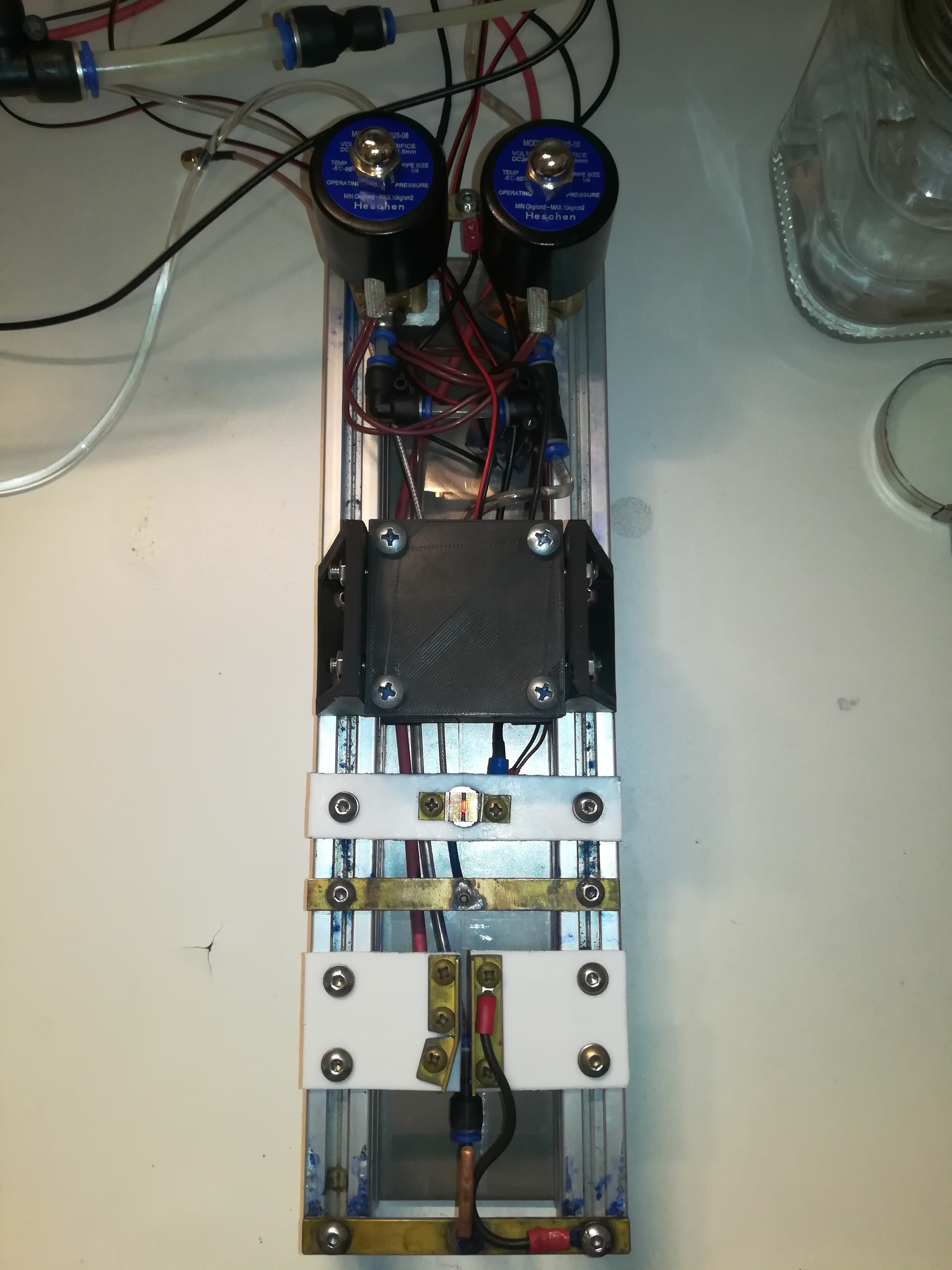
The "dirty ink" flows from the printhead through the main vacuum line to the vacuum puffer chamber and gets collected there. The vacuum puffer chamber has a float switch to shut the printer down or perform another action when it is full.
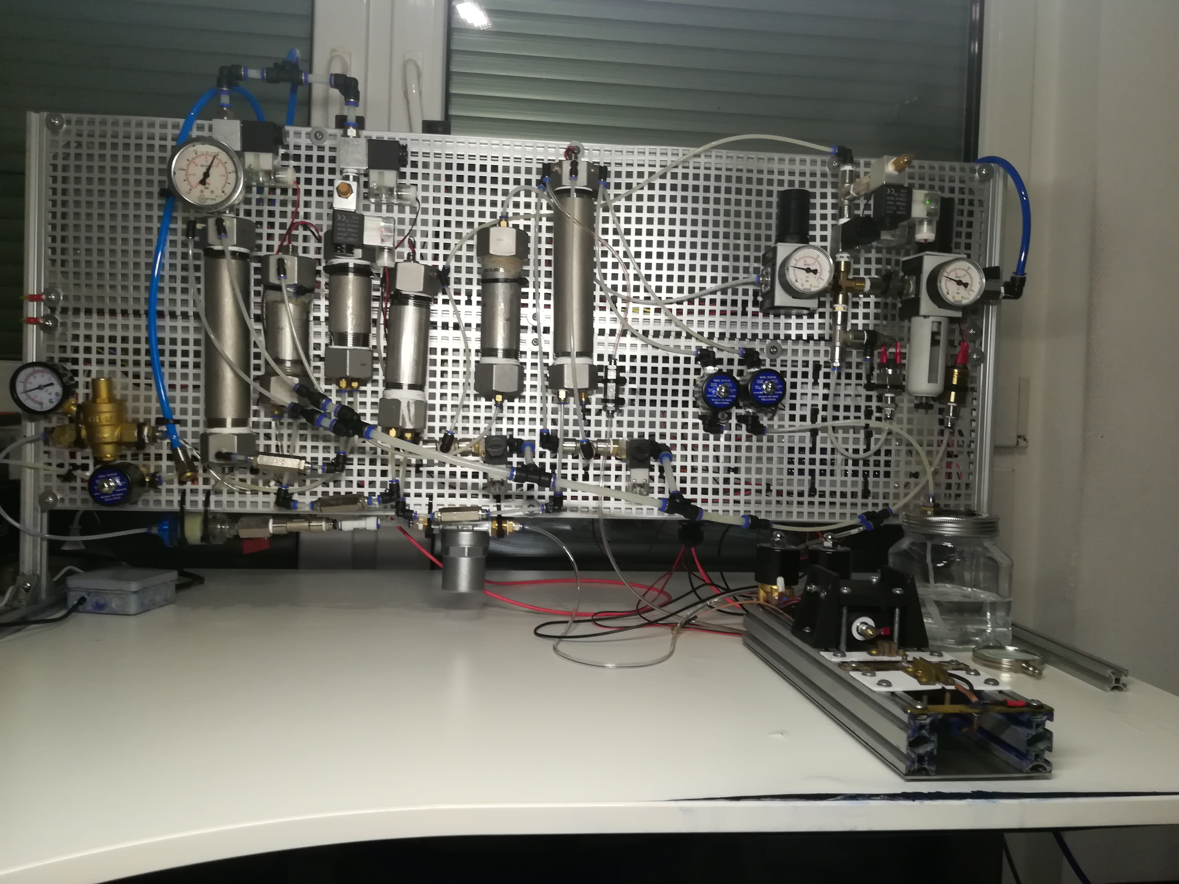
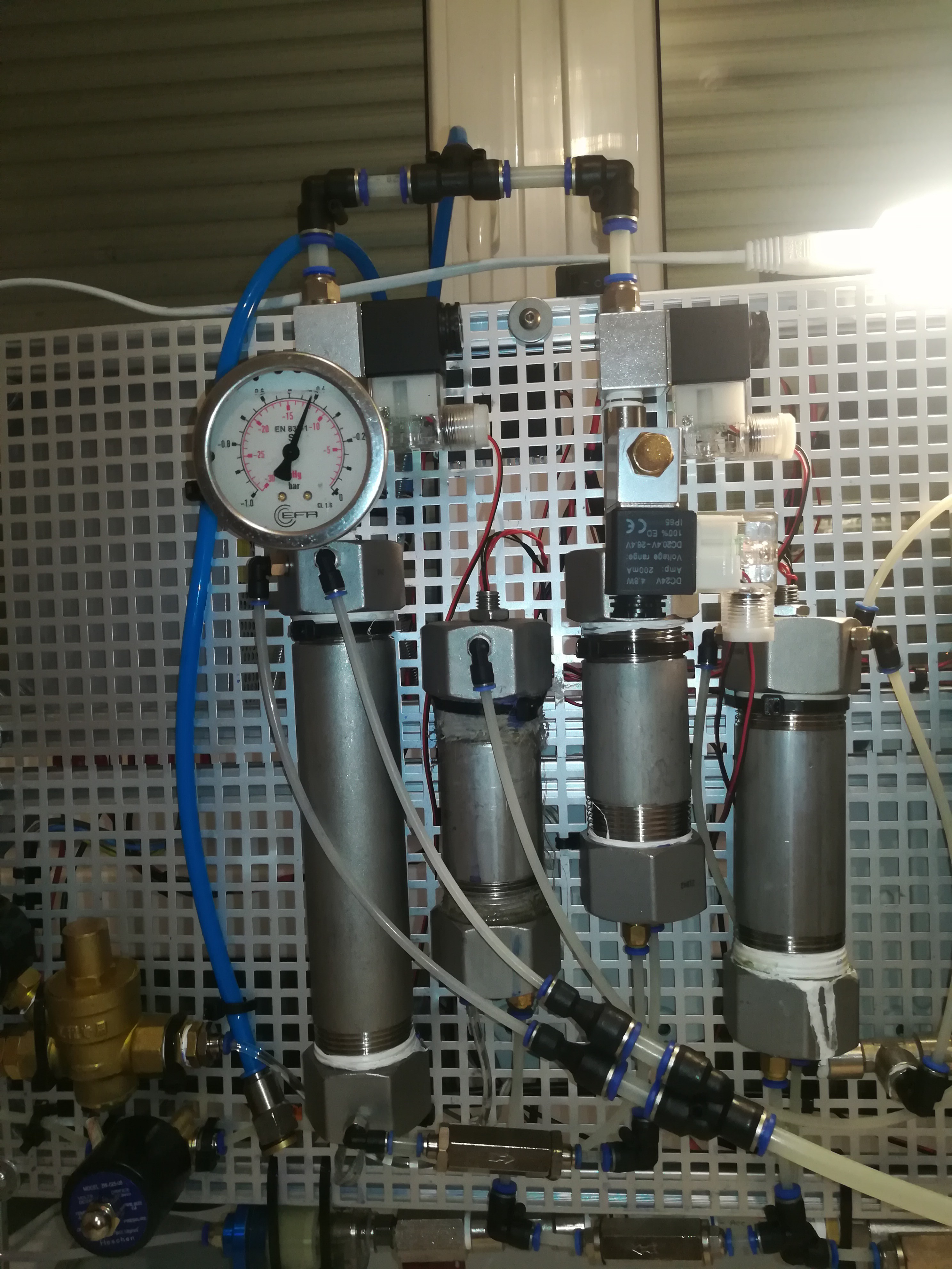
For draining the vacuum puffer chamber I added another chamber - a draining chamber to the printer.
The draining chamber has a valve for draining a valve for venting and a valve for vacuum.
For draining the vacuum puffer chamber, the vacuum of it is closed with the valve at the top. At the same time, the venting and drain valve of the draining chamber is closed and the vacuum valve of it is opened. By doing so the "dirty ink" is drawn through a check valve from the vacuum puffer chamber into the draining chamber.
When the vacuum puffer chamber is empty. The valve of it opens again while the vacuum valve of the draining chamber closes and the venting and drain valves of the draining chamber open.
The "dirty ink" that is now in the draining chamber can now exit the printer into a waste container.
With the newly added draining feature, it is possible to drain the vacuum puffer chamber which besides "dirty ink" also catches boiled-off ink and excess ink from the pump and reservoir chamber. The new feature makes it possible to drain the vacuum puffer chamber while the printer is printing. Otherwise, it would be required to shut off the vacuum first to drain the vacuum buffer chamber which would require a shutdown of the printer.
I think with the nozzle cleaning feature and draining feature nozzle clogging will be less of a problem.
Update:
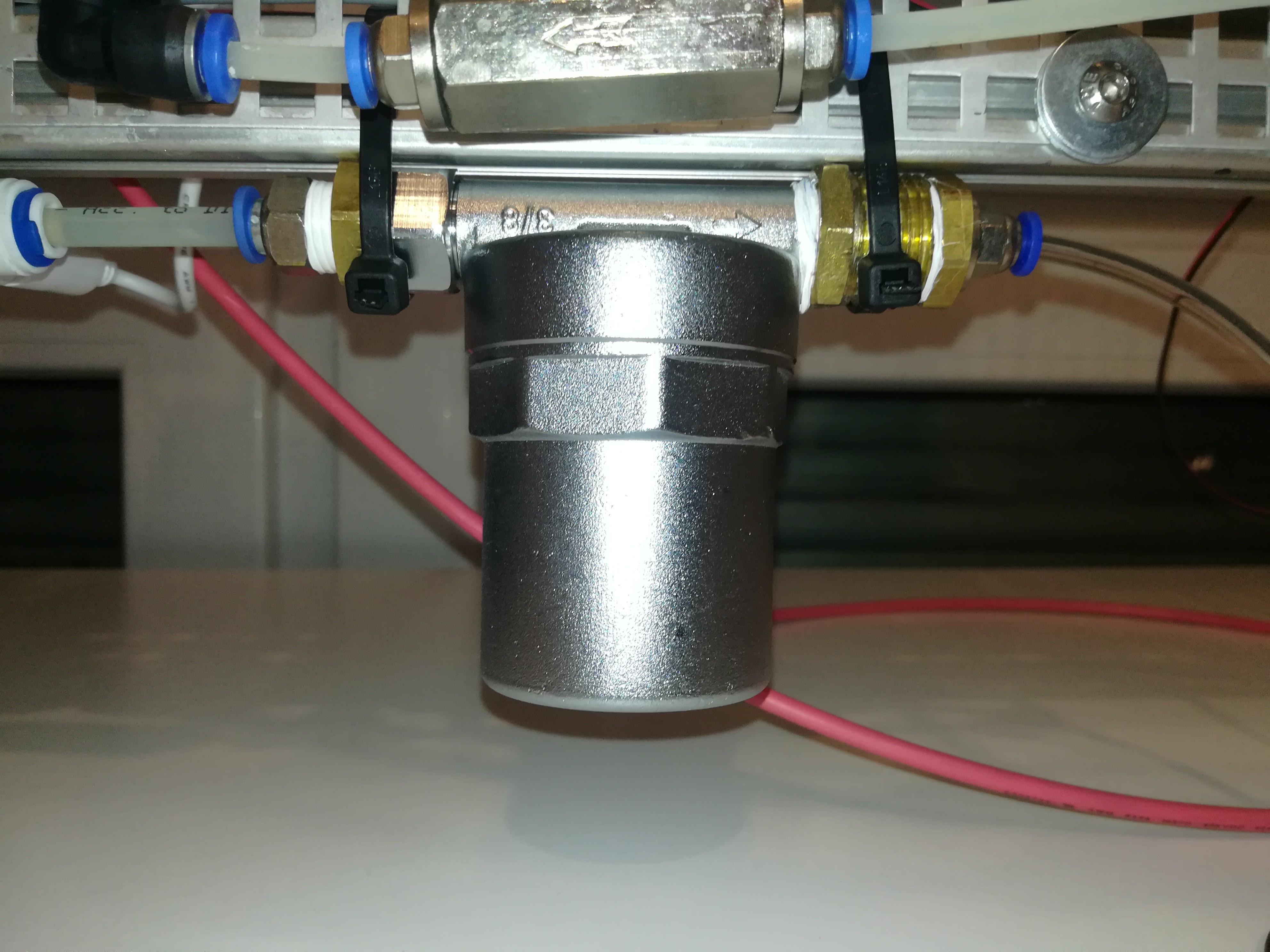
It turned out that the new filter was not corrosion resistant - what should be no surprise, given that it was made out of aluminum and galvanized steel, two materials which are not compatible with the ink....
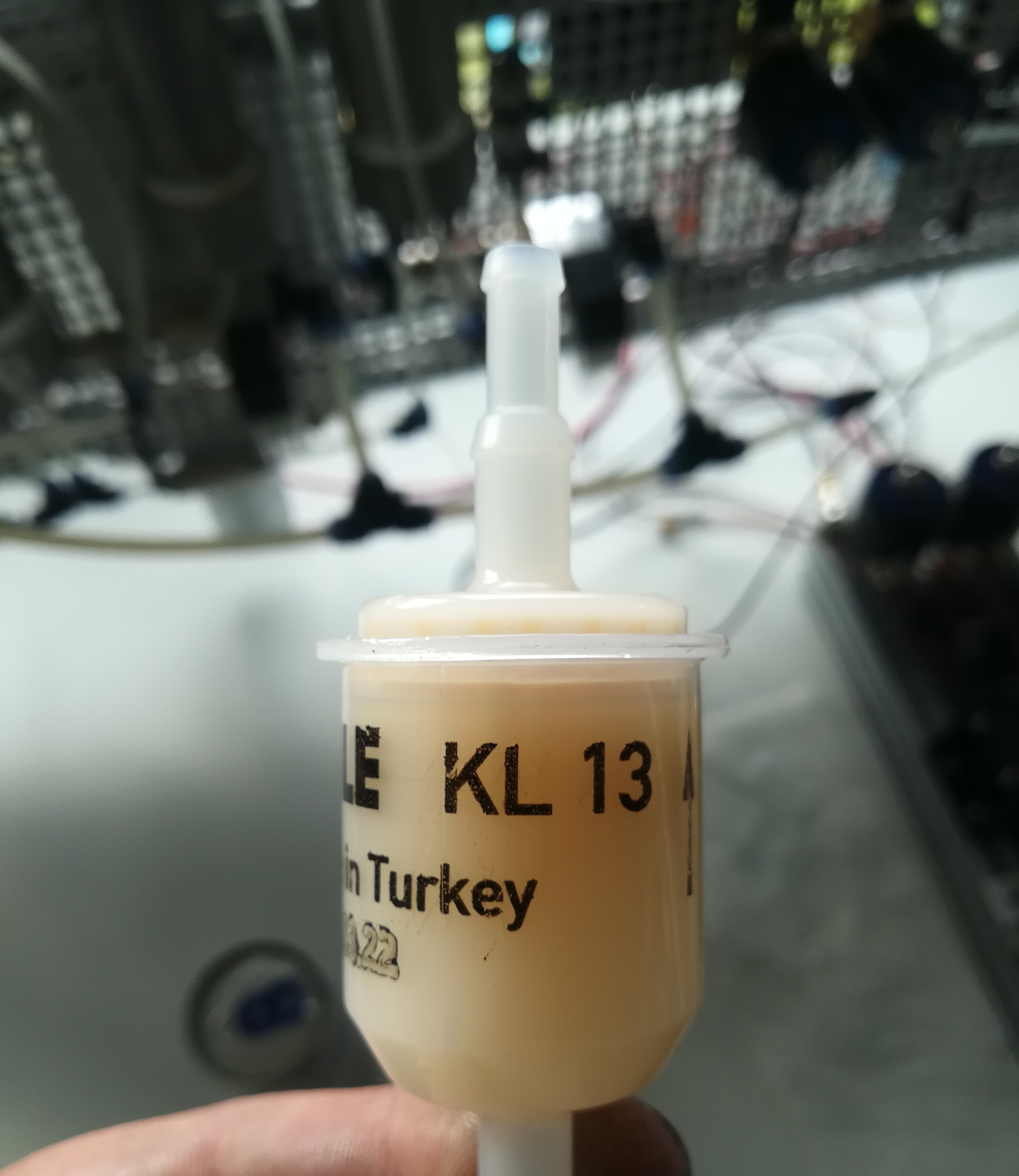
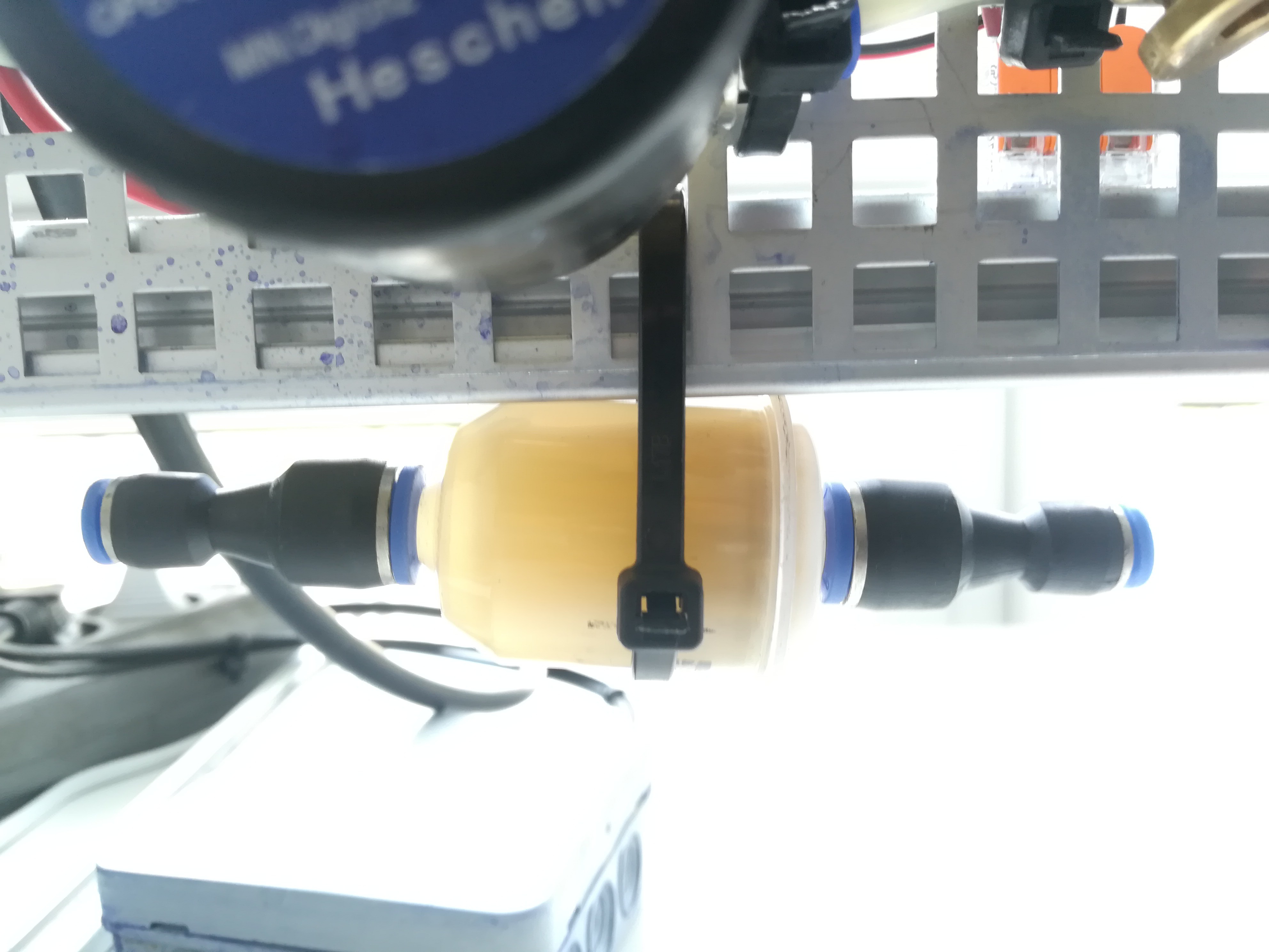
Because of that I'm now using a petrol filter again, like on the beginning of this project, but this time it is an steel free petrol filter.
There are many petrol filters out there which have galvanized steel parts in them which would start rusting and contaminating the ink. These are not suitable for the project and you have to use all plastic ones which are more corrosion resistant.
For now, this is the end of my report, and next up is the testing of the electrodes and trying to charge and deflect the ink stream.
I also want to test out mixing ink out of ethanol and PVB resin.
Discussions
Become a Hackaday.io Member
Create an account to leave a comment. Already have an account? Log In.