 Beko Pharm
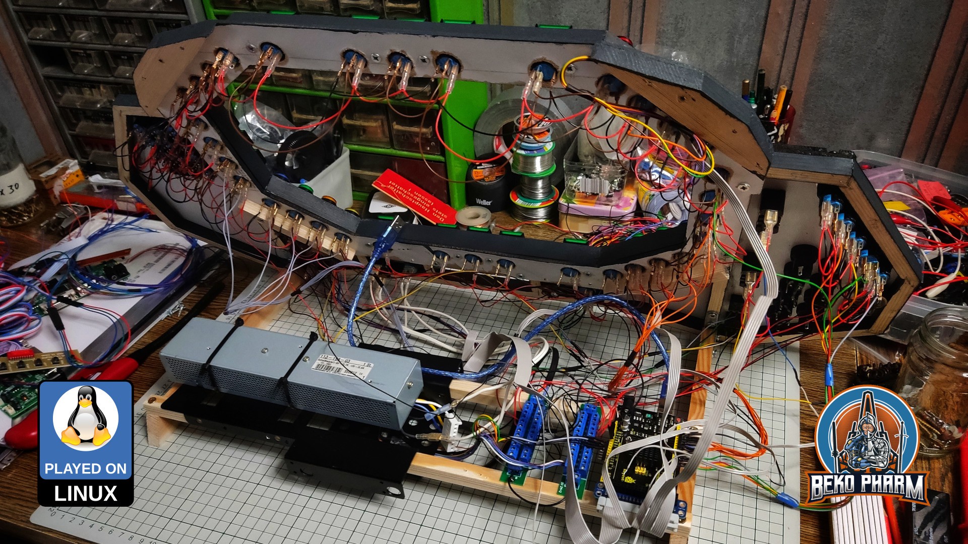
The last step in the construction was wiring everything up. That’s roughly ~250 connectors crimped and I usually remove the isolation with my thumbnail, which is a bad habit 🤪 I purchased crimping pliers just for this and I can totally recommend using such pliers. Used some leftovers from the frame construction to create two rails where everything else was screwed on. The black parts are 3.5" to 2.5" harddisk adapters I had laying around.
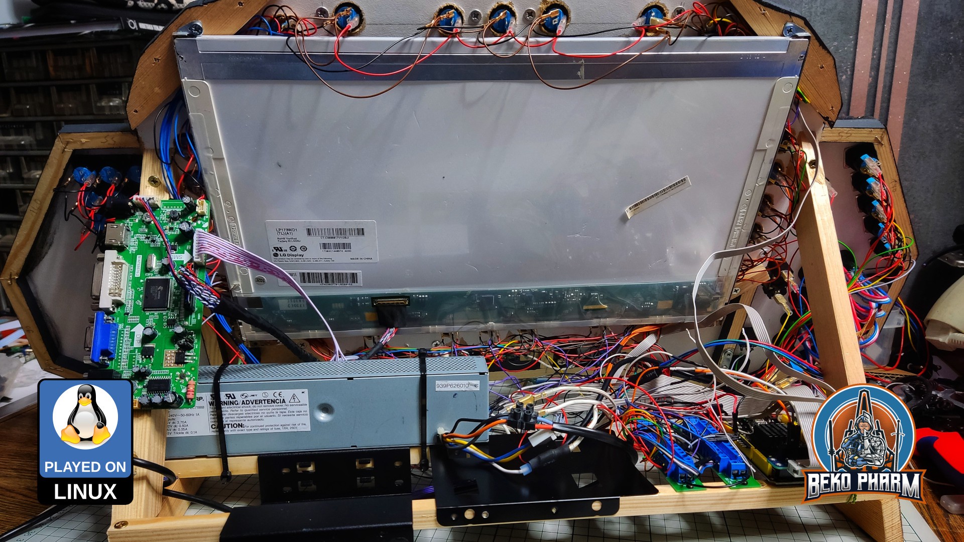
Next was connecting the LCD and see if everything survived the transplantation from version 1. The LCD is very bright on the backside, as you can see. The current version is still missing it’s planned glare shield that will also protect my other displays from the glare of the backside. That’s still to be done though.

After that came some rewriting of the custom joystick source code for the Arduino Mega. Many new buttons wanted to be read. I also removed the original buttons for the LCD controller and connected my own instead. Somewhere during connecting everything I noticed that I made an calculation error and a few buttons could not be connected because I was running out of free pins. So I’ll have to rewire some of the buttons into a button matrix (or use an IO expander - not yet sure what’s best for this).
The blinken lights were next. After that it was time to fix the wobbling. My “temporary” stand was no longer temporary and it was time to add some stabilizing bars. Convincingly this added exactly the space I was missing to fix the LCD controller board to the SimPit. Didn’t really plan this but with this I had all my connectors on the right side (my PC is also on my right).
Not too shabby considering I was winging it at this point.
Originally posted at https://simpit.dev/version-2/wiring/
Discussions
Become a Hackaday.io Member
Create an account to leave a comment. Already have an account? Log In.