After designing the Curilights, I wanted a way to easily control them without a computer attached. I came up with this controller, based on the mbed platform. The controller:
- Stores light patterns on an SD Card.
- Connects to a computer via USB for uploading patterns and animations.
- Has a menu driven UI with an LCD display for choosing color, brightness, patterns, and options.
- Optionally turns the lights off when the room is dark and no motion is detected.
- Turns the lights on if the room is dark and motion is sensed (night light mode).
The LCD user interface is based on a simple knob input. Turn the knob to change choices and push to make a selection. Using the knob is (like the iPod) immediately intuitive.
Controller Design
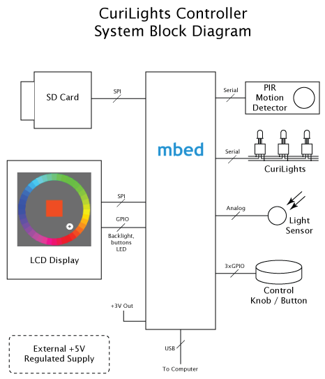
One of the benefits to using a MCU like the LPC 1768 is its ability to drive a full color raster display. This makes for a much cleaner and more intuitive user interface. For this system, a 1.5" Epson color LCD display is used for displaying menus and graphics. The primary interaction with the controller is a knob attached to a rotary encoder. Knobs make ideal controls, because it's easy to quickly turn past unwanted selections, yet easy to get fine control for desired ones. The knob also features a push-click momentary switch useful for confirming selections.
An SD Card is included for storing a catalog of patterns. This provides a straightforward way to update or add to the collection of patterns in cases where the controller is permanently mounted away from easy computer access. The USB port on the mbed module is also used for a couple purposes. First, the serial input connection is routed directly to the serial input on the string of lights, allowing the light string to be controlled directly by an attached PC. Second, new patterns may be downloaded via USB to the disk drive on the mbed. When the mbed is reset, any patterns downloaded on it's internal USB drive are moved over to the SD card for access by the controller.
Finally, two sensors on the controller monitor the lighting environment so the controller responds appropriately. A photocell connected to one of the mbed's analog inputs measures the ambient room light, so if the room is dark, the lights are shut off. A PIR (Pyroelectric InfraRed) motion sensor, however, “wakes up" the lights if motion is detected, making the system useful a night light.
Hardware
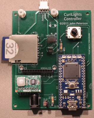
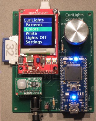 Figure 4 - a) System Board, b) With
Display Attached
The heart of the system, of course, is the mbed development board, based on the NXP LPC 1768 MCU. The rich set of on-board peripherals, timers, interfaces and memory all find use in this project.
The LCD display is an Epson LCD originally manufactured for Nokia 6100 series phones. Because of the tremendous volumes phones are manufactured in, these displays are now relatively inexpensive. This display comes mounted on a breakout board from SparkFun electronics. The breakout board simplifies the physical assembly and provides some additional circuitry for powering the display's backlight.
The display communicates with the MCU via an SPI interface using mbed pins 11 and 13, pin 14 is used to drive the display's CS (Chip Select) line (note the display is a “write only" device). The SparkFun breakout board has some additional peripherals including an RGB LED and two pushbutton switches. These are interfaced to the mbed, via GPIO lines. Although the current system doesn't use these, they may become useful as the software design evolves, so it made sense to wire them up.
Read more » J. Peterson

 Wenting Zhang
 RT-Thread IoT OS

For proper current control across connected LED's is I have to place resistor in series with each LED as mentioned in below article?
https://www.resistancecalculator.com/2020/02/resistor-for-led-calculator.html