Close
0%
0%

MORPH : Modular Open Robotics Platform for Hackers

An affordable modular platform for open robotics development for hackers. Provides a jump start to build your own robot.

Similar projects worth following
This project aims to build an affordable modular robot platform using open technology.

Features
- modular T-slot frame
- differential drive using two brushless DC hub motors
- driven by two open source speed controllers (VESC)
- uses Field Oriented Control mode to have near silent operation
- can carry a real load (~100KG)
- modular power supply built around a power distribution board with 3 in and 6 out connectors and separate DC-DC converters powered by one or more 10S2P battery pack(s)
- no central control board but separate USB controllers for each part, like ESC, gyro and bumpersensor
- targeting a 1000 euro budget for a mobile base robot which can navigate an environment

Why

The robot revolution is happening and it's in need of more open and modular technology! Providing an open source platform to build a robot will help anyone having a robot solution in mind to jump start development for that solution. Not only a small robot for learn or play, but a real close to human size robot which can carry a significant load in order to perform a real world task. Making a modular and open platform will allow anyone to build this and change this to their own needs. The platform should be affordable, targeting a 1000 euro budget for a mobile base robot which can navigate an environment. This project focuses on the mobile base first, but adding generic end effectors or complete robotic arms is definitely the next step.

Background

There aren't that many robot platforms out there that you can buy and start building your own robot. There are a *lot* toy-scale platforms, but somewhat larger, closer to human-size and able to carry a load, not so much. The ones that do exist either are targeting commercial use and are priced accordingly (~10K euro) or have other serious limitations. When I wanted to build my own robot a year ago and looked for a platform to build it on, there were basically two options which came close. The Turtlebot 2 which uses the Kobuki base and the Parallax Arlo platform. I had a budget in mind with of around 1000 euro. This already excluded the Arlo, which would take up the complete budget and then some, on the mobile base alone. I have some experience with the Kobuki in real life and was generally disappointed with the noise and small payload ability (~5KG) and the relative high price tag of 350 USD (without shipping). At the same time the 'hover'boards became popular, can carry a real load (~100KG), operate silently due to their brushless hub motors and are relatively inexpensive (~200 euro). I remembered seeing the VESC, an open source brushless electronic speed controller project (on Hackaday off-course) and the idea to combine them into a robot platform was born. I wanted to build a robot which I could use, but was also designed with some principles in mind, to allow the project to be open and reusable by others.

Applications

The applications are endless. The low price makes it feasible to have a fleet of robots doing specialized tasks. There are a lot of applications that are possible, which are built around a mobile base and do not require a robot arm yet. Here are some ideas:

  • camerabot or robotic tri-pod
  • smart trashcontainer which moves to a central location when it needs to be emptied
  • waiter bot serving drinks or snacks from a tray
  • smart storage container which picks up contents or brings its contents when needed
  • robotic furniture or walls to have a dynamic room layout
  • robotic (vacuum) cleaner
  • robotic lawn mower
  • endless surface CNC-bot
  • robotic (shopping) cart

MORPH:

Modular
To be truly modular there should be no limitations up front. The design should be extensible, but also allow parts of it to be replaced by something else. In the end building a robot should be as easy as building your PC, build a frame, add a power supply, wheels, sensors, computer and add or develop software.

  • Total physical modularity: it should be possible to change the appearance or design of the robot to meet a desired solution. This is accomplished with the use of T-slot profiles which allow you to rapid prototype the design of the robot to build the solution you need.
  • Total electronic modularity: instead of one big controller board which is designed up-front with the capabilities required the electronics is build around a modular power supply and modular electronics with separate USB controller boards for each input / output.
  • Total software modularity: the ROS driver is built around the ros_control library with a implementation of the wheel driver interface to allow controlling the wheels in different configurations. Currently the robot is designed as a differential drive mobile base, but with the wheel driver...
Read more »

  • 2 × 350W brushless DC hub wheel motor Can be harvested from a hoverboard
  • 2 × brushless electronic speed controllers (VESC)
  • 1 × 10S2P 36V battery Can be harvested from a hoverboard
  • 1 × T-slot profiles with mounting accessoires Various lengths depending on the design
  • 1 × USB hub I used a cheap 10 port USB hub to allow plenty of expansion possibilities

View all 9 components

  • MORPH base testdrive

    Roald Lemmens10/15/2017 at 20:33 0 comments
  • Panels

    Roald Lemmens07/28/2017 at 08:42 0 comments

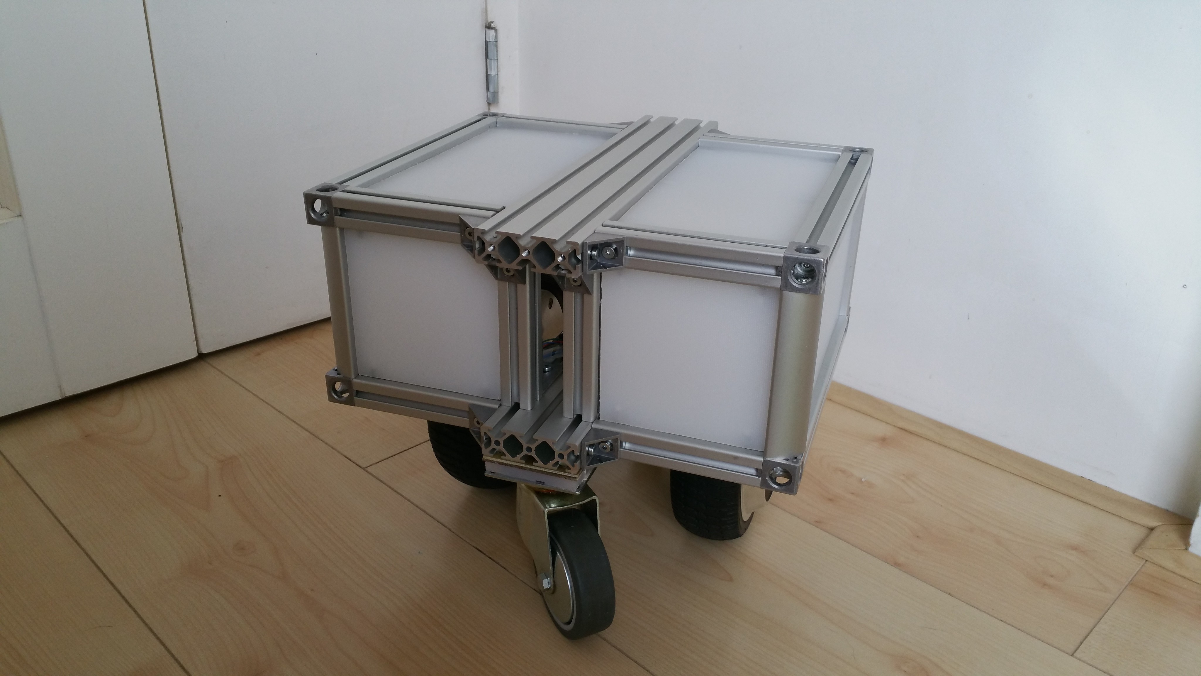
    This is just a short update to show the result of added panels. I removed the additional supporting beams which were used to mount the USB hub and Up board. Instead these will be mounted on the panels saving some space. Although the idea is to add a fleece skin to the robot, the panels provide protection for the electronics and make for a more generic base.


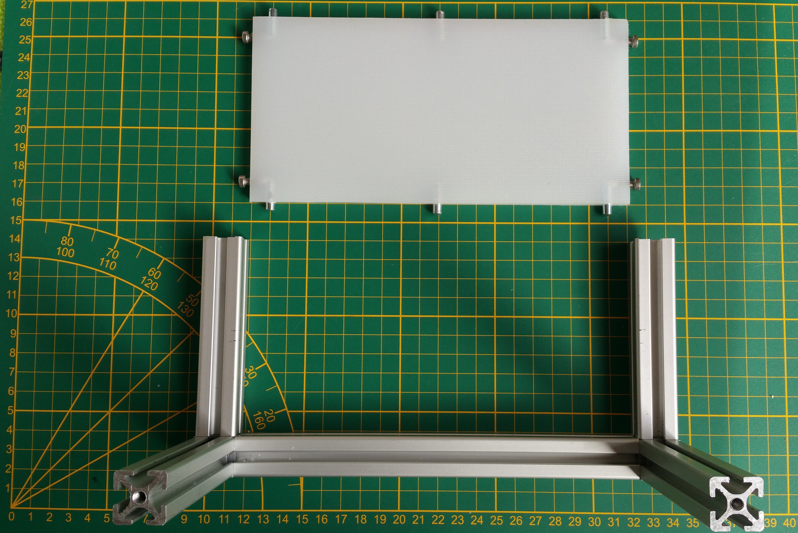
    The panels are made from the same 8mm polyethylene as used before (a.k.a. Ikea chopping board). The panels slide in the slots with M4 bolts. The other sides have 5mm rods which provide additional support.

  • Design #5: Stronger enclosed base

    Roald Lemmens07/24/2017 at 08:35 1 comment

    At this point I had a design that worked pretty well. But still there were things I wanted to improve:

    • change the frame to be able to carry a load
    • protect the electronics
    • change to a more generic mobile base
    • improve the caster wheels ground clearance

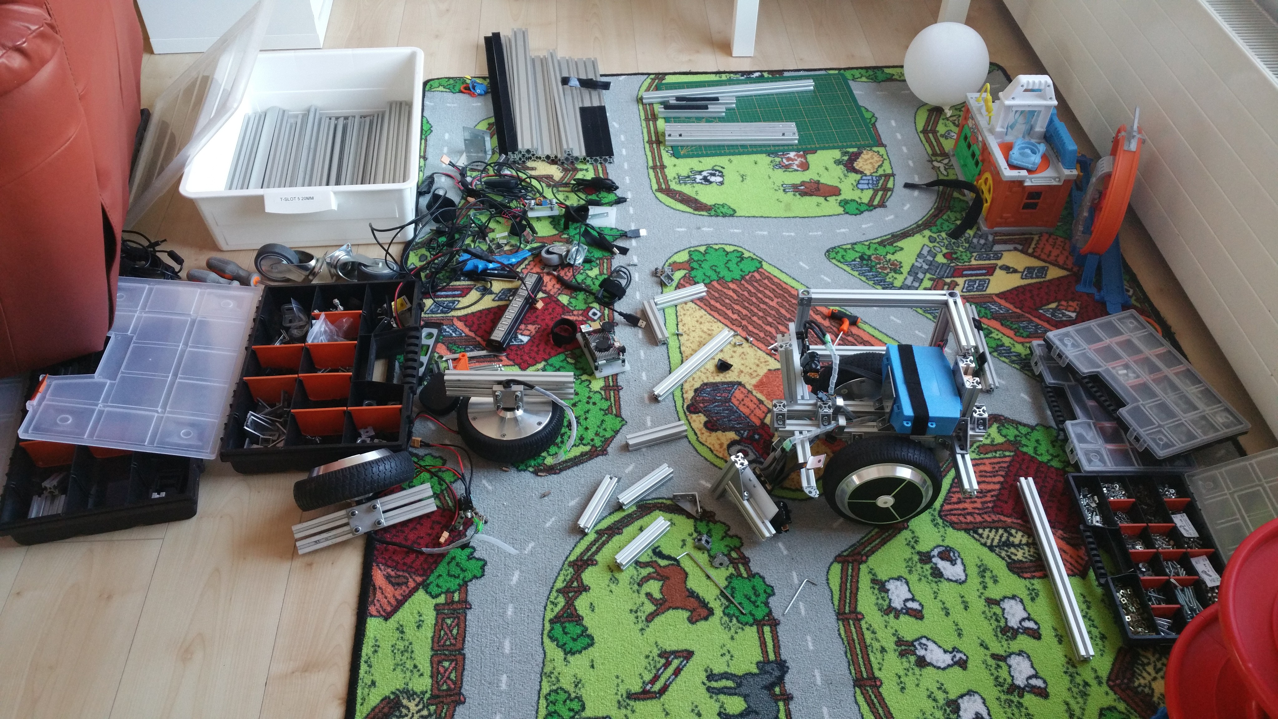
    So I started another redesign. Which is actually a fancy word for saying I took it apart and started playing. Often I was assisted by my two fellow designers, my 8 year old daughter and 6 year old son, sharing a workspace together.

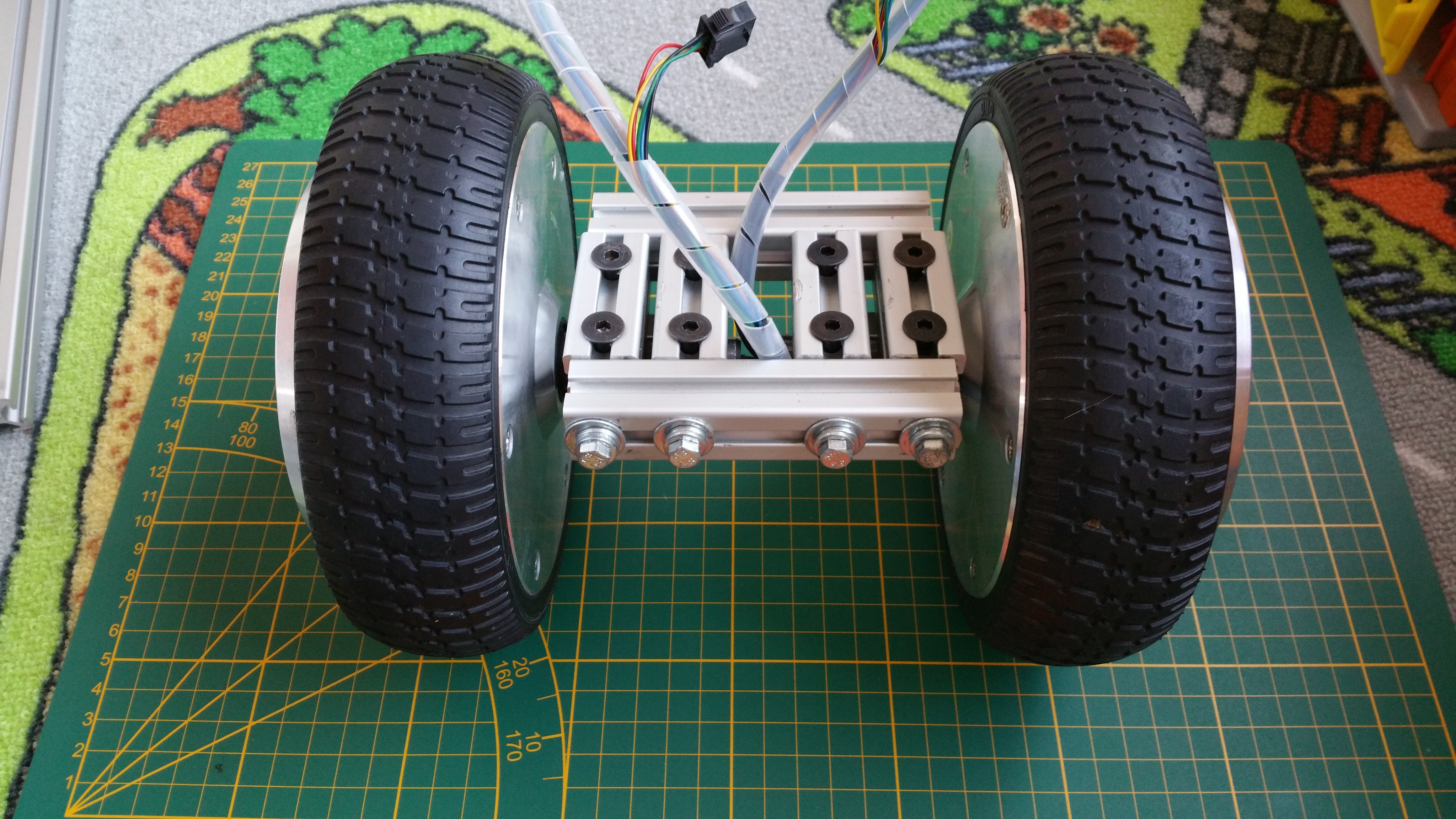
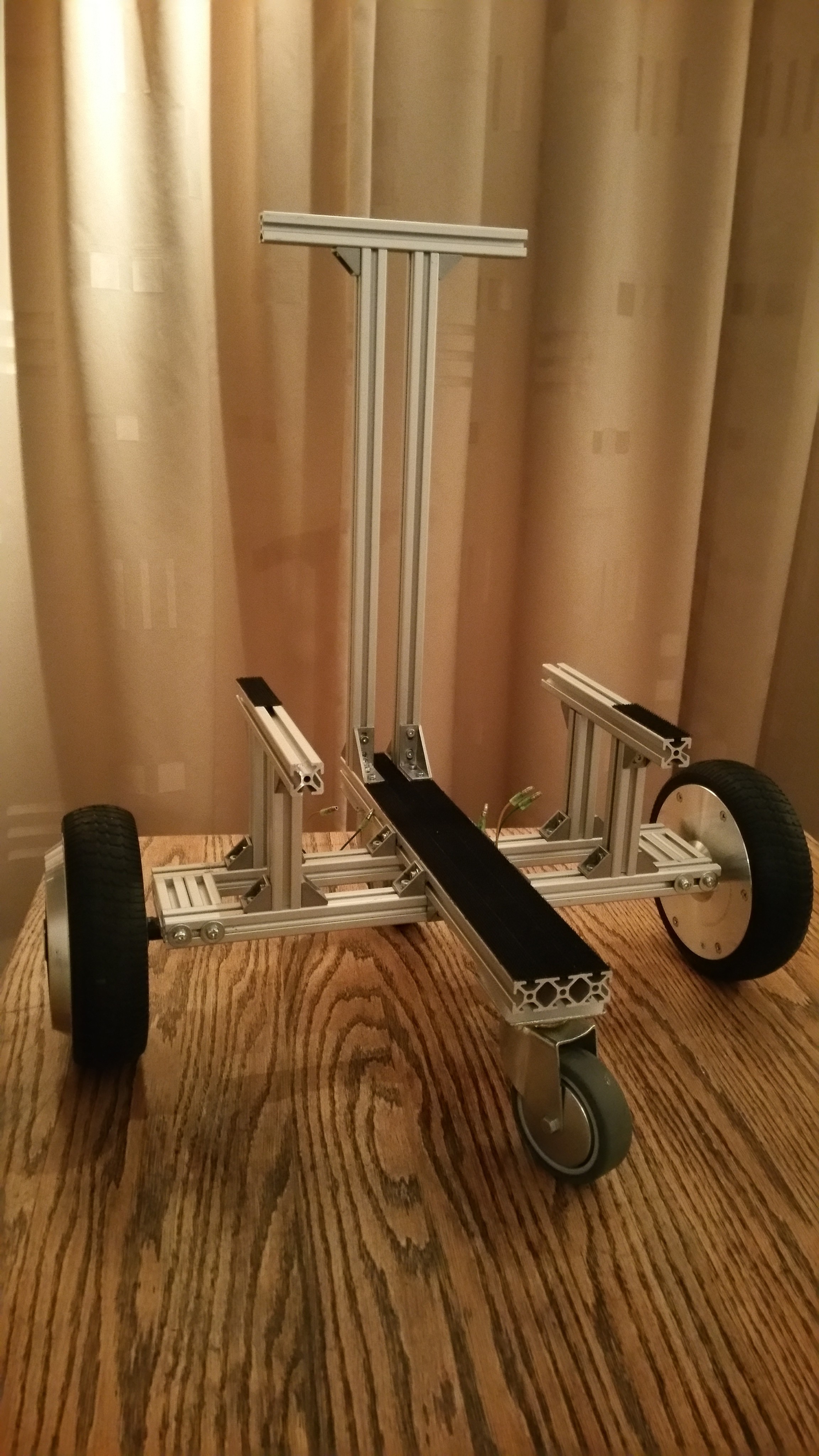
    I started changing the way the wheels were mounted. Before I focused on modularity having two separate wheel assemblies connected to the frame. But now I focused on creating a small frame which would distribute the load better.

    Read more »

  • Wheel encoder mount

    Roald Lemmens07/22/2017 at 08:26 0 comments

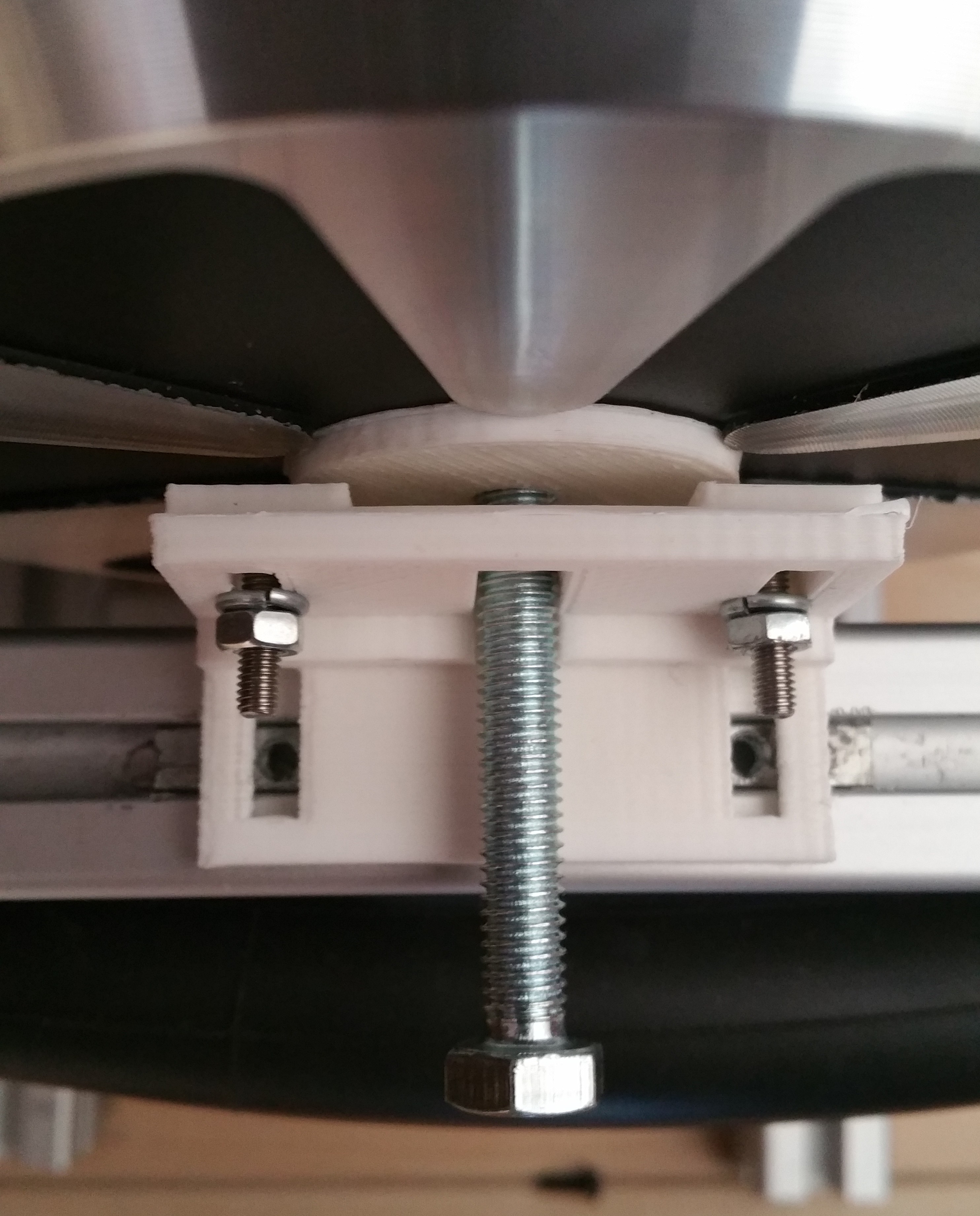
    For the wheel encoders I used the AS5047P development board. As a first attempt to mount the encoder on the new frame I used a piece of MakerBeam connected to two small angle brackets. While this somewhat worked, it relied on visual alignment. This was actually more guesswork since it's very hard to to see if the sensor was properly aligned. This needed some improvement, so I designed some brackets in OpenScad. Basic idea was to have an angle bracket with mounting slots to allow the positioning of the distance to the wheel and a sensorboard holder with mounting slots for further vertical alignment. At first I designed this as a 2 piece design, with the angle bracket as a single piece.

    Read more »

  • Source code morph stack

    Roald Lemmens07/21/2017 at 08:00 0 comments

    I've linked the main repository containing the source code for the morph stack for use in ROS. The stack consists of separate packages, each have their own repository but are linked as submodules from the main repository which is linked.

    • morph_bringup : contains launch files and parameters for bringing up the robot
    • morph_description : provides the robot model
    • morph_hw : provides the robot driver for creating a differential drive mobile base
    • morph_navigation : contains launch files and configuration parameters for using the navigation stack
    • morph_teleop : provides launch files for teleoperation of the robot using keyboard or X-box controller

    I've forked the VESC repository from the MIT-Racecar project in order to merge the commits of pull request 7 which contains changes to publish the rotor position. I've been testing this to get more detailed odometry.

    See the readme of the morph repository for installation instructions. This is very much a work-in-progress but at least it will show the current state of development.

  • Design #4: Improved concept

    Roald Lemmens07/18/2017 at 18:29 0 comments

    With good results from the encoder it was time to address some of the issues and do another (you guessed it) redesign. Let me start by showing the result first, for a change. I will go into the details after the break.

    Read more »

  • Encoder

    Roald Lemmens07/18/2017 at 07:57 0 comments

    In order to improve the odometry data I wanted to add an encoder. The downside of using a brushless DC outrunner hub motor is there is no shaft to mount an encoder to. The shaft fixed to the robot remains stationary and only the wheel turns. The VESC already had support for the AS5047 magnetic rotary sensor and I read a positive experience about that sensor. It seemed doable to mount a magnet to the side of the wheel, so I ordered some development boards. The development board contains the sensor mounted to a small PCB and a diametric magnet of 6mm diameter and 2.5mm depth.

    First step of testing the encoders was removing the RC filters on the hall sensor port as Benjamin describes very clearly in his video.

    Read more »

  • Design #3: Initial concept

    Roald Lemmens07/17/2017 at 08:30 0 comments

    At this stage I had a simple proof-of-concept, but with some flaws I wanted to address:

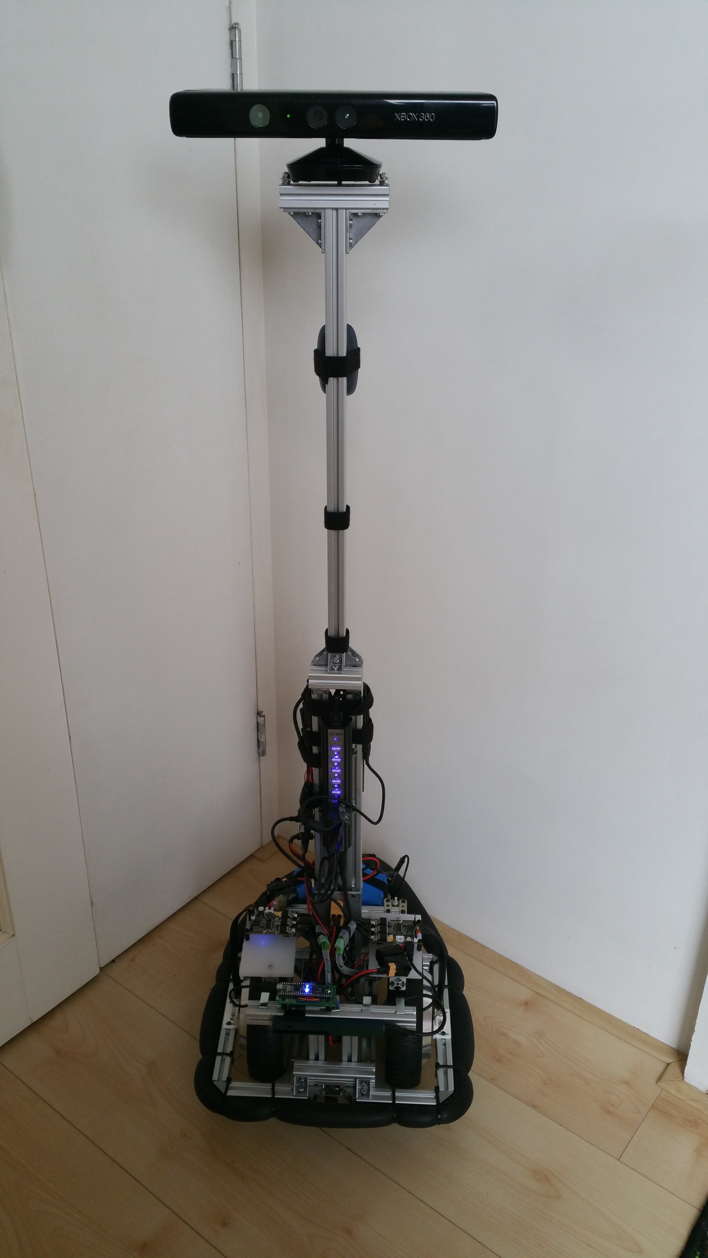
    • I didn't like the Turtlebot-shape of the robot, I wanted a more close to human size robot (around 1m50 / 1m60) which could carry a load.
    • The wheels mounting brackets were failing. The added weight of the old laptop caused the brackets to misform.
    • The old laptop I used was too slow to run gmapping in order to try to create a map and also had some Wifi reliability issues.
    • The VESC's were driving the motors in BLDC mode, causing a high-pitched noise while driving. I wanted to drive the motors in FOC (Field Oriented Control) mode, which should make them more quiet.
    • The large inrush current caused by the VESC's capacitor banks would trip the safety of the BMS integrated in the battery pack, which meant I couldn't use the switch to turn on the robot, but had to connect each VESC's power one by one.

    So it was time to start over and try a new design. Instead of just a test frame, I started building a first version of the concept I had in mind. Things were changing at a rapid pace and I should have documented better to have something more to show for it.

    Frame design
    I drilled 6mm holes in an 6x2cm T-slot profile beam and mounted the wheels with M6 bolts with the mounting blocks which were harvested from the hoverboard. The frame was made smaller and taller.

    Read more »

  • Design #2: Turtlebot-like test frame

    Roald Lemmens07/16/2017 at 17:48 0 comments

    For the next step, I wanted the robot to be controllable from ROS. I changed the initial design to be more Turtlebot-like to be able to hold a laptop running ROS.

    Changing the frame was the easy part, most of the work has gone into creating the ROS integration. Thanks to the MIT-Racecar project, there already was an open source VESC driver which I could use. This meant I didn't have to implement the serial communication which saved a lot of time. Because I wanted a modular solution I wanted to implement the driver using ros_control. In ros_control a robot driver exposes joints which can be controlled using a velocity, effort or position interface. For wheels this means we need to implement the velocity interface. The velocity interface accepts the desired target speed as a command (in rad/s) and reports the actual speed as feedback of the current state (also in rad/s off course). The joints are controlled using a controller implementation, for which ros_control already provides some, including a differential drive controller.

    Read more »

  • Design #1: Test setup

    Roald Lemmens07/15/2017 at 20:44 0 comments

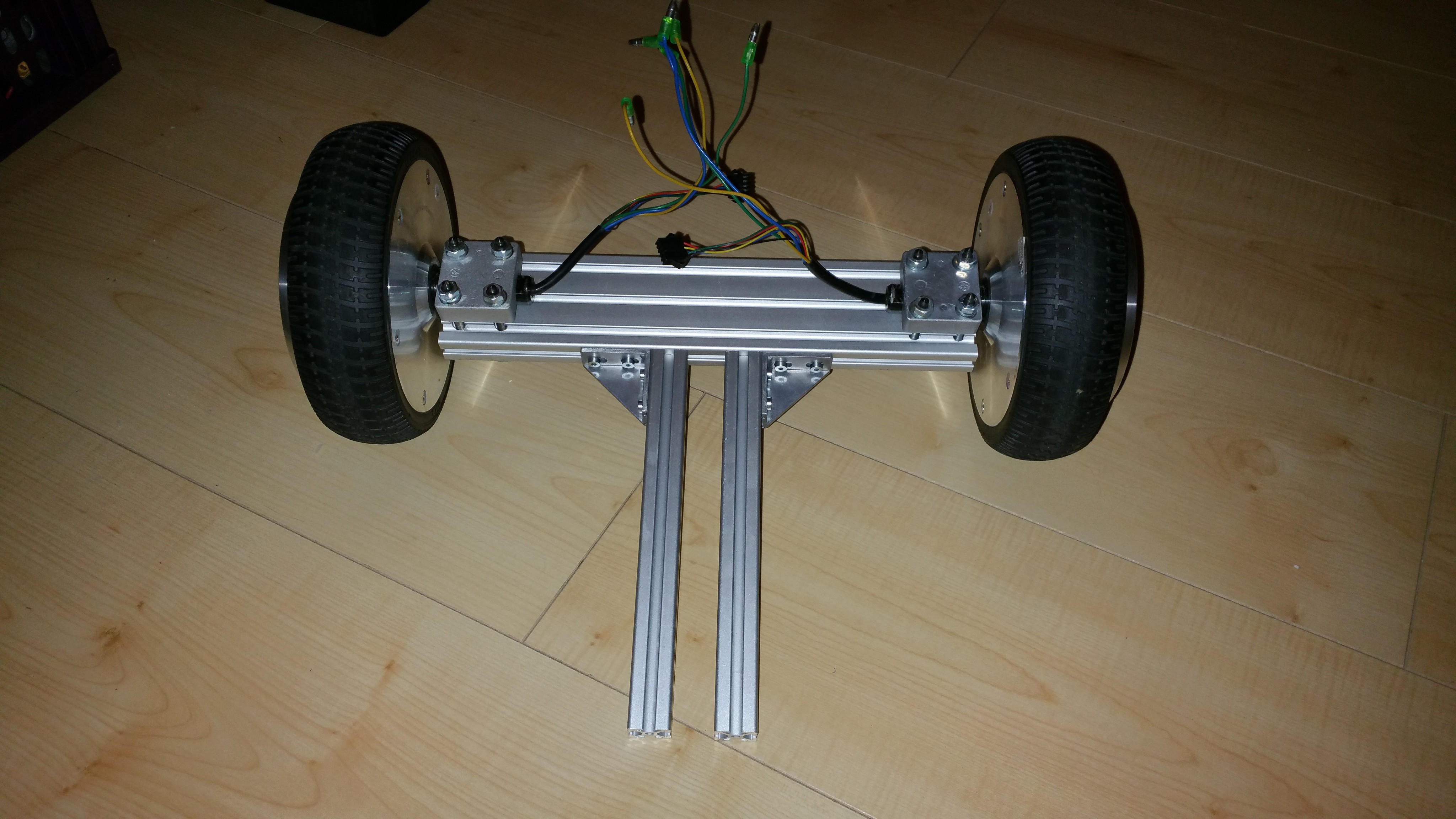
    This has been a pet project for about a year now, and I would like to start by giving a short summary of the past design iterations. While having a general idea in my head, I didn't start with a clear end-design. Instead I focused on rapid prototyping each step to test each assumption along the way and iterate the design.

    I started out by harvesting the parts from the hoverboard.

    Read more »

View all 10 project logs

Enjoy this project?

Share

Discussions

rajmeetsng wrote 10/12/2021 at 17:04 point
Which motor driver is used to control the hub motors.

  Are you sure? yes | no

Roald Lemmens wrote 10/14/2021 at 05:57 point

As mentioned in the text a VESC (hardware version 4.20). There are different manufacturers, like Flipsky and Maytech.

  Are you sure? yes | no

Jaime Andres Rincon wrote 05/25/2020 at 19:48 point

Hi, I have a question related to the AS5047, how do you know if the motor rotates clockwise or counterclockwise?. I use an Arduino to get the rotation angles of the motor, but I can't determine its direction of rotation.

Greeting

  Are you sure? yes | no

Starhawk wrote 09/21/2019 at 23:54 point

I live on less than your budget for one robot, for an entire month. 1000 EUR is not "affordable" unless you are a university or other similar research institution.

Divide by ten. At /least/ ten. I can afford 100 EUR or thereabouts. That's about a month's disposable income for me.

Use crap from eBay and Amazon. Use stuff you can get at Walmart and (dare I say) dollar stores. For example: why the big fancy custom chassis out of expensive aluminum channel and Ikea plastics? Angle brackets and Walmart cutting boards... or, you know, a big plastic tub and a bit of wood or cheap plastic or metal rods (heavy duty plant stakes, maybe?) for reinforcement. Lawnmower wheels from the Walmart garden center are another good idea. They're dirt cheap... and relatively sturdy. Certainly sturdy enough for this.

Electronics? Use sealed lead-acid batteries. The kind APC puts in those battery backups for home offices... 7.5AHr 12vDC. $22 a pop at Walmart. Yes they are heavy. But they have a huge capacity, and you can charge them literally with an unregulated wall-wart and a single resistor. (The caveat: charge time is ~18hrs because you have to do it at the 1C rate if you don't want to make a mess.) Motors should be 12v or 24v. Maybe look into Razor scooter motors and cheap Chinese knockoffs... ditto ESCs. Heck, a full-on homebrew ESC may be a savings here... although don't forget that Mouser charges a minimum of $5 for shipping, and chips from eBay generally just don't work.

If you can be creative enough, it's doable. I think. Go for it!

  Are you sure? yes | no

Starhawk wrote 11/09/2019 at 17:28 point

No response...? Shame, shame...

  Are you sure? yes | no

Jana Marie wrote 05/15/2019 at 17:49 point

Hey, nice project! :)

Any specific reason why you use the VESC? I would suggest using hoverboard mainboards. One costs ~17$ and covers both motors. The mainboard can be controlled via UART, I2C, PPM and analog input. https://github.com/NiklasFauth/hoverboard-firmware-hack

There are already some Open-Source Robotics platform projects using hoverboard hardware (one by me :3):

https://twitter.com/TheVale98/status/1109271786888355840

and

https://github.com/Jan--Henrik/transpOtterNG

  Are you sure? yes | no

Roald Lemmens wrote 05/16/2019 at 21:04 point

Hi,

Thank you! When I started this project there were some people trying to reuse the  Hoverboard mainboards, mainly by imitating the gyro boards.  For robotics it's helpful to have feedback in order to do odometry. The VESC is a very good ESC that provides that, but comes at a high price. It was quicker for me to use the VESC and got good results. But I'm very interested in reducing the price and see if the hoverboard mainboards are a viable option. So thanks for your links and input, I will take a look!

  Are you sure? yes | no

Humpelstilzchen wrote 05/19/2019 at 12:15 point

Does anyone have checked how well these hoverboard actuators handle lower speeds at 0.2 - 0.5 m/s? These are the speeds you usually want to drive your robot during indoor operation.

  Are you sure? yes | no

Apollo Timbers wrote 12/12/2018 at 21:11 point

I'm a sucker for any project based around T-Slot :)

  Are you sure? yes | no

Robin Fröjd wrote 05/06/2018 at 06:51 point

maybe this is the problem after updating the firmware https://github.com/mit-racecar/vesc/issues/11

After updating the FW I get very strange massages in sensor/core topic. Do you have any ide how to fix this? :-) 

  Are you sure? yes | no

Roald Lemmens wrote 05/07/2018 at 20:17 point

Hi, from reading the discussion I see you found and fixed the issue and that it's indeed related to the firmware. Great work :). 

  Are you sure? yes | no

Robin Fröjd wrote 05/07/2018 at 20:30 point

Hi Roald. Yes I fixed the problem :) It was related to the FW. I remapped the bytes in vest_packet.cpp. Here is the fix if somebody else reads this: https://github.com/raess1/vesc/blob/master/vesc_driver/src/vesc_packet.cpp

But thanks anyways :-)

  Are you sure? yes | no

Robin Fröjd wrote 05/05/2018 at 21:48 point

Hi, I have now everything setup. using encoders as5048a. when i try to control the vesc with morph.hw I now get Dutycycle out-of-range left_wheel and same on right wheel.  Any suggestions on how to fix this?

  Are you sure? yes | no

Robin Fröjd wrote 03/30/2018 at 14:32 point

I read you also had some encoder problem at the beginning. Did it look like this? https://www.youtube.com/watch?v=R189nbmtxeU

Would I need to get shielded cables or what do you think?

thanks 

Robin

  Are you sure? yes | no

Roald Lemmens wrote 03/30/2018 at 18:10 point

Looks more like an alignment issue with the magnet. At least similar to what I had when the magnet/sensorboard position was not perfectly aligned. When I had issues with the cable the values went all over the place. But some shielding is required, I'm currently using a flatcable in which each odd wire is connected to ground.

  Are you sure? yes | no

Robin Fröjd wrote 03/31/2018 at 17:45 point

Thanks. I actually ordered a bunch of different encoders to try out. Which include AS5047P, AS5047D,  AS5048A and amt102v. I will test them all and see how or if they work. I am printing a new test rig now that will be better aligned for testing. I also made a shielded 8 lead twisted in pairs cable now with a S-GND for testing. Let’s see how this works out. :-) happy easter 🐣 

  Are you sure? yes | no

Roald Lemmens wrote 04/01/2018 at 06:51 point

I'm very curious to see how the different encoders compare. Happy easter!

  Are you sure? yes | no

Robin Fröjd wrote 04/03/2018 at 08:30 point

Thanks for the reply! I made an homemade shielded cable from an old network cable with 8 leads twisted in pairs and with S-GND to the Foil and the noise is gone. 

It also took some time to remove the hall sensor filter on the VESC (flier) model, since they moved all the mosfets to one side on the PCB, Making the Layout different from the original. After some investigation I managed to locate and remove it.

But I have problem reading the degrees 0-180. It works perfect for 180-360. I tested the AS5047D and the AS5048A. 

I also tested to use ABI Interface for the AS5047D and that works perfectly 0-360 degrees. Did you have any problem with 0-180 degrees over SPI?

I will try the AS5047P later today and see how that works over SPI and maybe ABI if SPI doest work :)

here is a small video on the AS5047D: https://www.youtube.com/watch?v=VoYjUqWflZY

  Are you sure? yes | no

Roald Lemmens wrote 04/04/2018 at 18:12 point

That's weird... I only have experience using the AS5047P over SPI. But it seems others have this issue as well with that type and using ABI does work (as you already discovered :) ). Check out http://vedder.se/forums/viewtopic.php?t=72

  Are you sure? yes | no

Robin Fröjd wrote 04/05/2018 at 12:45 point

Thanks for link. I'm actually active in that thread. :)

Anyways, I got some tips from Benjamin to ignore the MSB and use 13 bits instead of 14 with the following code in encoder.c

void encoder_tim_isr(void) {

uint16_t pos;

spi_begin();

spi_transfer(&pos, 0, 1);

spi_end();

pos &= 0x1FFF;

last_enc_angle = ((float)pos * 360.0) / 8192.0;

}

With this hack the AS5048A was able to read positions from 0-360 degrees. (Did a fast test on the launch brake ) and I was having some minor problems with noise/alignment. So I will do more tests tonight to confirm.

One would try to avoid using ABI mode since that only gives a valid angle after detecting the index pulse , so SPI is to prefer. 

I also found out the modifications on the VESC is not absolutely necessary. One can Define the VESC  to use HW SPI pins instead (that would saved me a bunch of time) :-)

#define AS5047_USE_HW_SPI_PINS 1

  Are you sure? yes | no

Robin Fröjd wrote 03/26/2018 at 22:17 point

Any success recovering the hall sensor coding?  :-)

Anyways I also ordered some encoders now. the AS5048A and also the AS5047P.  May I ask if you are running a self build VESC´s or did you buy it? in that case from which brand? Did you remove the R11-R13  and jumpered R8-R10 to get the encoders to work on the VESC´s?

Thanks!

  Are you sure? yes | no

Roald Lemmens wrote 03/27/2018 at 06:05 point

Sorry for the late reply, reality caught up and didn't have time to look into the code this weekend. I'm using the AS5047P, if I remember correctly the difference between some models are related to the speed it can handle and also if a magnet is supplied. I think the VESC should be able to work with the different types. I got my VESC from Enertion Boards and had to remove the 3 RC-filters which are there for the hall sensors, so removed 3 resisters and 3 capacitors and added 3 bridges. Benjamin Vedder (the guy that created the VESC) describes this very well in this video about encoder support for the VESC: https://www.youtube.com/watch?v=8CcqD5sw90U. I think you should be able to mount the encoder in the drive train, as long as it has a 1:1 ratio to the output you would like to position. At least that's done for servo's, but then again I'm not 100% sure if the VESC's firmware would support this scenario. Only one way to find out ;).

I'll send you a PM with the code I had, maybe that helps.

  Are you sure? yes | no

Robin Fröjd wrote 03/27/2018 at 08:44 point

Thanks Roald. The ratio between motor and shaft is not 1:1, so I guess mounting them on the drive shaft is not an option. I designed a new mount for the encoders making it possible to mount the magnets on the back of the motor (the motor also have holes on the back, so I can make a small bracket for the mangnet) 

Here is the design : http://a360.co/2IpzNX0

What do you think? 

I have two VESC´s made from R-snake flier model. So i guess I need to do the same mode as you did. 

Looking forward to test the code with hall sensors also, But in the end the encoders may be the way for better absolute position. 

Here is a quick and dirty test of the drive system

https://www.youtube.com/watch?v=rY8JqbOhSeQ

Still doing final adjustments before CNC milling the motor brackets. The noise is cooming from the 3D printed brackets (unstable). But for a first test they suffice. :)

All the best

  Are you sure? yes | no

Roald Lemmens wrote 03/28/2018 at 18:53 point

Nicely designed frame! Good to have the flexibility to add brackets like for the sensors. Only thing I would be worried about is the alignment of the sensor relative to the motors. Since you're using a single bracket for both wheels and the bracket is fixed, you can only align it by changing the position of the motors. But it looks like you can only move the motors in 1 direction and perhaps change the depth with some spacers or washers. Since the alignment is critical for the sensor and greatly influences the smoothness of control I would make the bracket and sensor mount adjustable. Maybe designing a calibration tool to mount on the motor which determines where the sensor board holder should be placed. Again very cool project and lots of progress in a short time!

  Are you sure? yes | no

Roald Lemmens wrote 03/27/2018 at 08:25 point

I looked at the changes I did to implement the encoder and it seems it should be possible to use hall sensors with the current code. Although the encoder position is calculated and logged, the displacement values from the VESC are still used and these are calculated by the VESC also for hall sensors. So I think you should be able to run the differential drive without code changes and simply disabling the encoder in the launch file. This is still something I would like to test as soon as I have some time for this.

  Are you sure? yes | no

Robin Fröjd wrote 03/21/2018 at 21:46 point

Got the VECS´s and motor running over ROS with your morph stack. :-) 

some questions you maybe can help me answer?

1. With hall sensors what Parameter for enabling rotor position publishing should I use? I saw that you use default="encoder"


2. When I try to echo the rostopic /right_wheel/sensors/core and rotor_position I get no values. Is this because of the default="encoder"?


3. Where Can I calculate this values

<param name="left_wheel_ikv" value="8.543328017" />
<param name="right_wheel_ikv" value="8.821034775" />
<param name="tacho_pulses_per_revolution" value="90" />

here is a video of the test: 

https://www.youtube.com/watch?v=f4ZobjZOBfo

many thanks for the ROS drivers! :-)

  Are you sure? yes | no

Roald Lemmens wrote 03/22/2018 at 17:39 point

Very nice progress! And cool project, by the way :).
Rotor position publishing is only possible with an encoder which provide an absolute rotor position, so it makes sense you get no values with the hall sensors. I should have kept support for using hall sensors in the code. I still want to do another test with hall-sensors instead of the encoders to see how it performs. I'll lookup the code I had and add support for both type of sensors. Hopefully I will get to this in the weekend.
I determined the 'ikv'-values by calculating the KV for the maximum dutycycle (I used 95%) for the input voltage. I used the values provided by the VESC for the voltage, ran the motor at 95% dutycycle (without load), noted the ERPM, converted the ERPM to RPM (dividing by the motor poles) and divided the RPM by the input voltage. So in short:

((ERPM @ 95%)/motor poles)/input voltage

The value is used to calculate the duty cycle based on the voltage. But there are probably better ways to do this :).  Feedback is always welcome!

- right motor:
    - @ voltage 41.6V => ERPM 0.95 duty cycle: 9814 => 344,35 RPM => 8,277665317 KV
- left motor
        - @ voltage 41.9V => ERPM 0.95 duty cycle: 9830 => 344,91 RPM => 8,231796675 KV


  Are you sure? yes | no

Robin Fröjd wrote 03/22/2018 at 18:12 point

thanks! :-) And thanks for answers. Let me calculate this values too see what I get. I tried changing the (encoder) to pid_pos and are receiving some values now when echoing the sensor/core. Haven’t looked into it more. My motors use internal pcb with 120 degrees hall sensors. 

So I’f I where to mount enconders where can I get the AS5047P? I found the AS5047D https://www.mouser.se/ProductDetail/ams/AS5047D-TS_EK_AB?qs=sGAEpiMZZMsSgQ5oX0A7uvuLN6qMB2aDFPMW%2fVFC97KeWVyQMYHC9A%3d%3d

And also some other AS5047 with different letters. Will VESC striclty only work with the P type?

I will not be able to mount the enconders on the wheels or the motor.  But I have place for them on the drive shaft that’s uses belt drive from motor (gearing the RPM down) do you think I can mount the enconders on the drive shaft?

Also did you modify the VESC in order to get the enconders to work? I looking for the best possible solution to get exact position.

Thanks

Robin 

  Are you sure? yes | no

Robin Fröjd wrote 03/20/2018 at 12:26 point

Got my new motors up and running now. https://www.youtube.com/watch?v=ha5ucyqyUr0

Any tips & suggestions to make them more silent and handle lower speeds better?  I am running FOC and Hall sensors.

  Are you sure? yes | no

Roald Lemmens wrote 03/20/2018 at 18:53 point

Looking at the VESC BLDC-Tool it seems you have measured the hall-sensors but the values are not applied, since the table for the hall sensors values show 255 only, but the table for the detected values show different values. Maybe applying (and for safety saving and restarting the VESC) will help. When I setup a new motor I always perform:

- 'Measure R and L', followed by 'Apply' in the same row

- 'Measure lambda' (I use 3A, 0.05 dutycycle for the hub motors I have)

- 'Calc CC'  followed by 'Apply'

Then detect encoder (at 3A) for the AS5047 I use, or in your case the Detect hall sensors. Finish with 'Apply' and 'Write configuration' . Then you should be able to test the settings.

  Are you sure? yes | no

Robin Fröjd wrote 03/21/2018 at 10:19 point

Thanks. The motor works fine now :) https://www.youtube.com/watch?v=FVqr6PI0G7I

The hall sensors is working and feeding me data. I will try out your ROS driver tonight and see how it works out :) 

Thanks!

  Are you sure? yes | no

Robin Fröjd wrote 03/12/2018 at 08:39 point

Love this project! What ROS driver did you use too control the VESC simultaneously? 

  Are you sure? yes | no

Roald Lemmens wrote 03/12/2018 at 11:20 point

I created a ros_control driver which controls the differential drive and uses the vesc_driver package from the mit-racecar project to control the individual wheels. You can check the github link https://github.com/roaldlemmens/morph and specifically the morph_hw package. There's still room for improvement to get the wheels to run at exactly the same speed and allow the robot to move in a perfect straight line.

  Are you sure? yes | no

Robin Fröjd wrote 03/12/2018 at 11:23 point

Thanks for the fast reply Roald, Let me have a look at the link. I am going to use two BLDC motor running VESC on my project. I will receive them on friday. Then I can test your package. :)

  Are you sure? yes | no

malvasio.christophe wrote 02/12/2018 at 07:37 point

with 2 motors omnidirectionnal any numbers of wheels chassis are possible

  Are you sure? yes | no

Similar Projects

Does this project spark your interest?

Become a member to follow this project and never miss any updates