Close
0%
0%

Game-o-Tron Mini

A roughly credit card sized gaming handheld

Similar projects worth following
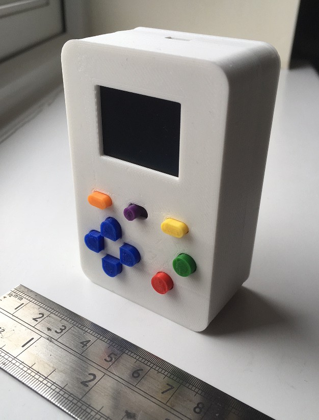
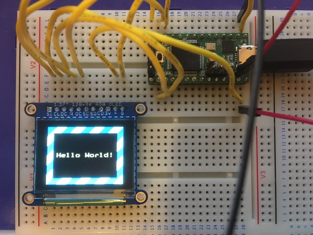
The Game-o-Tron Mini follows on from my previous Game-o-Tron consoles (See "things I've built") and will be a small gaming handheld (roughly the size of a credit card) powered by a Teensy 3.2 with a 128x96 pixel OLED screen and sound. As well putting the hardware together I'll also be developing some games for it.

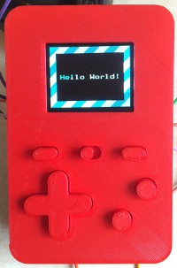
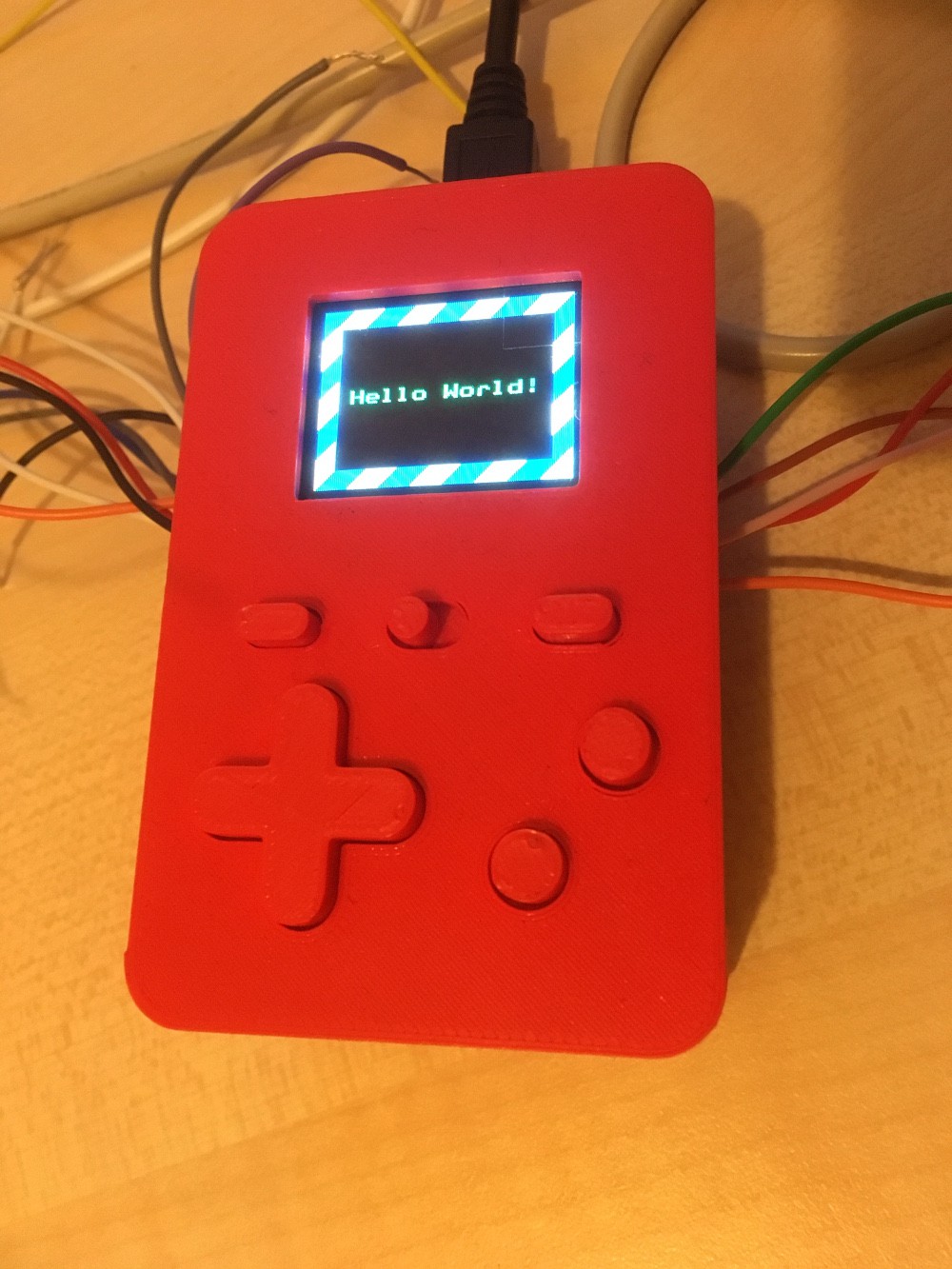
The project photo shows the completed hardware. It is powered by three AAA batteries. The AA battery is there just to give you an idea of the size.

Full details will be added here eventually but for now, here is my plan for the main components:

  • #19 - DPad fail

    David Boucher02/05/2018 at 19:59 0 comments

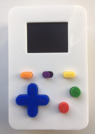
    As you can see, I've replaced the dpad with four direction buttons:

    Now I've started developing games, I've found that the dpad just doesn't work as well as I would like. The four direction buttons are better; the operation is smoother and it's easier to get the direction that you want.

    So what was wrong with the dpad? I've used dpads similar to this one in other devices which worked well so what went wrong here? I think there are a few things:

    • Rounding off the corners of each direction was a mistake. It looks nice, but it means that there is less surface area to press, meaning that your thumb has to be positioned more accurately.
    • This device is much smaller than previous ones that I've built and although the dpad itself is about the same size as earlier ones, there is very little space below it. This means that you can't rest the ball of your thumb on the case and operate the dpad by moving the tip of your thumb up, down left or right. Instead you are forced into a bent thumb posture, where you lift and press on each individual direction. This requires more accuracy.
    • Finally, in earlier designs I have used switches with a very short travel, the same ones that I have used for the pause and option buttons here in fact. These are rectangular and where I have used them in dpads, they were arranged with their short side facing the centre of the dpad. There was a small gap between the bottom of the dpad and the switches and a piece of foam rubber was used in the centre to stop the dpad rattling about. This time, I used rubber capped switches as I thought this would give the dpad a better feel. It did, but the function was much worse. As the dpad was now constantly in contact with the switches, pressing in one direction would apply pressure to the switches in the adjacent directions. This meant that if you weren't quite centred when pressing, for example, up, you would get up and left or up and right. I made a few changes to the dpad and was able to improve this somewhat but never got it to work as well as I wanted.

    The result of these things is that you have a dpad that demands precise presses to behave correctly and anything else can result in it registering the wrong direction, which translates into a frustration playing experience. Splitting the dpad into four direction buttons was a quick fix that dramatically improved things. I think that there are for two reasons for this:

    • There is no longer a mechanical connection between the directions, so pressing one direction cannot register spurious readings in the adjacent directions.
    • Having four individual buttons provides better tactile feedback. There are more edges and so it is easier to register where your thumb is by touch.

    Of course, the downside is that you can do things like press up and down or left and right together, but as hardware designers say: "we'll just fix that in software".

  • #18 - 3D printed part files

    David Boucher12/27/2017 at 16:18 0 comments

    I've uploaded the 3D printed part files. The download contains the original .scad files and also .stl files generated from those in case anyone wants to print them without installing OpenSCAD. They are licensed under CC BY-SA 4.0.

    The link can also be found under the external links section on the project page.

  • #17 - Hardware Done!

    David Boucher12/02/2017 at 12:29 3 comments

    Finally, the hardware is complete:

    I will be making the .scad and .stl files available for download soon. The software is still far from complete, so that's the next job.

  • #16 - That took a lot longer than I thought it would

    David Boucher11/18/2017 at 11:49 0 comments

    I've finally got a 3D print of the case parts that I'm happy with, which actually looks better IRL than it does in the picture below:

    This took a few attempts to get right as I was having problems with poor bed and layer adhesion and I had to adjust the printer settings for the new filament, but I've finally got there and I just need to print the buttons now.

  • #15 - Dpad fine tuning

    David Boucher10/28/2017 at 14:14 0 comments

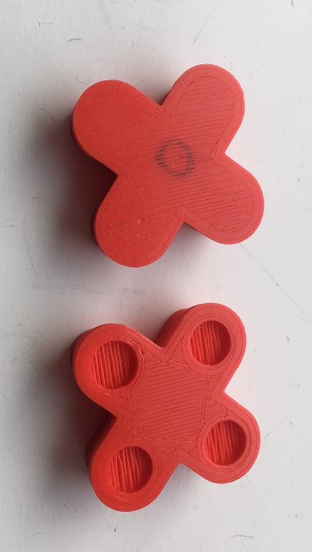
    As mentioned in the last log, I had a problem with the Dpad, where pressing one of the directions would in some cases trigger one of the adjacent directions, so pressing up might unintentionally get you left or right too. To fix this, I've added recesses to the bottom of the Dpad so that there is not enough pressure applied to the adjacent directions to trigger them, unless you deliberately press a diagonal.

    I've also fixed the other issue that I mentioned regarding the size and positioning of the hole for the screen, so what should be the final, final, case front prototype is printing as I speak.

  • #14 - Wiring done, what's next?

    David Boucher10/16/2017 at 19:30 1 comment

    I've now finished wiring everything up and the screen, buttons and sound all work, so what's next?

    1. The aperture for the screen is slightly too large, exposing a little too much of the non-displaying part of the screen at the bottom. A small adjustment to the case front will fix this.
    2. It's too easy to unintentionally press a diagonal on the dpad. I think that this is because it is a little too small and moves around too much in its hole. Hopefully making it slightly bigger should fix this.
    3. Complete the case front and design a back for it.
    4. Re-print the external parts in their final colours. 
    5. Programming. Lots of Programming.

  • #13 - The Hunt for (a bug in something that is) Red (in) October

    David Boucher10/08/2017 at 10:31 2 comments

    And with the contrived title out of the way, I'll explain.


    After connecting up the screen (as above) I noticed an annoying problem: roughly a couple of times a minute I would get display corruption. It would only last for one frame, so roughly 1/40th of a second, but it was noticeable. Arrgh!

    As I'd not seen this on my breadboard prototype, my first thought was that it was either a bad connection or having all the wires wedged in close together was causing interference. Checking for a bad connection was the simplest thing to start with, so I tried shaking it and prodding the various wires (with something non-conductive or course) with it switched on. Neither of these things triggered the problem, so maybe it was something else?

    To check if interference was the problem, I disassembled the electronics from the case so that the wiring could be spread out a little. I thinking was that if interference was the problem, this would reduce or eliminate it but when I powered everything up there was no change and I still saw the occasional corrupted frame.

    After checking the supply voltage and trying a few different power supplies to no effect, I decided to look at the software. The first thing that I did was lower the SPI frequency. This eliminated the problem but at a cost of reducing the frame rate. Maybe there was a better way?

    I looked at the code that sends the display data over SPI as this is where the bulk of the time is spent. For each line of the display, SPI.beginTransaction() is called, a line data is sent using SPI.transfer() and SPI.endTransaction() is called. Would moving the SPI.beginTransaction() and SPI.endTransaction() calls outside the loop work and would it improve performance?

    I tried it and it did work and the bug did not return however it was not significantly faster. For some reason, I decided to try it with the SPI frequency increased back to its original setting.

    The bug did not return. I got a rock solid display at 40 FPS. I tried increasing the frequency further. The bug still did not return. I was able to increase the SPI frequency to its maximum value and get a whopping 80 FPS, more than enough for my purposes.

    I can't say exactly what the problem was here, or even if the problem was with the Teensy or the screen, but it seems that performing an SPI transaction for each line was causing some sort of stability problem and doing one transaction for the entire screen instead fixed it. I would be interested to hear you theories in the comments. 

    In any case, the end result is one squashed bug and a performance improvement!

    AN UPDATE AND CORRECTION (11th December 2017):

    I've discovered today that there is an odd problem with this in that it is only stable at this speed with certain colours. bright primary and secondary colours are fine, but other colours occasionally get corrupted part way down the screen.

    I first noticed this on a test screen with orange text on a black background. Sometimes the bottom part of the screen would render as red text instead of orange. As far as I can tell, a single bit is being lost somewhere, changing the colour of each subsequent pixel. Depending on the original colour, this may or may not be noticeable.

    The only way I've found to fix this is to lower the SPI frequency. This has brought the frame rate of my current test program (which is doing a bit more than the one I was using in the original post) from 63FPS to 36FPS. :(

  • #12 - I really need to learn how to design PCBs

    David Boucher10/02/2017 at 19:29 1 comment

    This log is just a quick progress update. I've printed a cut down version of the case front as an assembly aid and started connecting things up. There is still plenty to do but the screen works now:


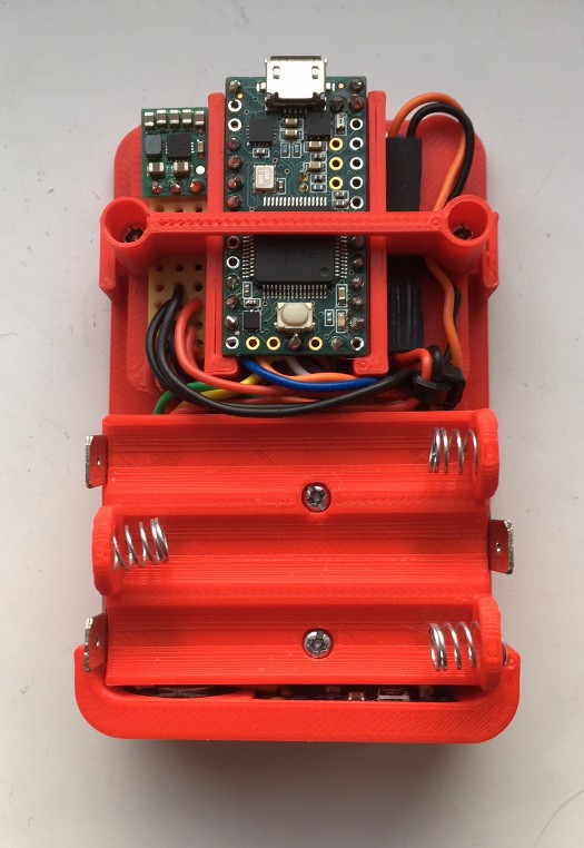
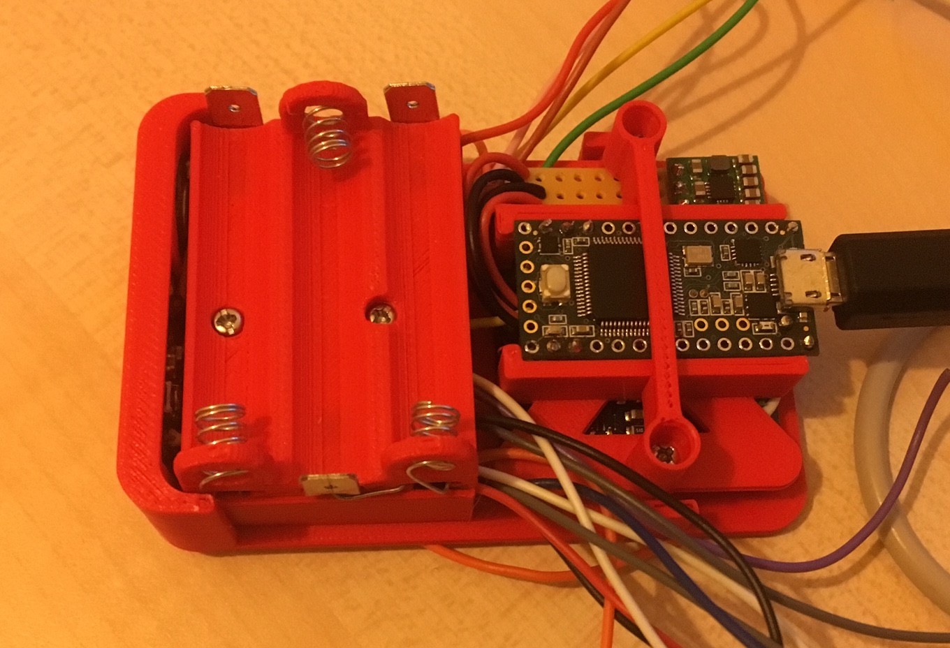
    Here is what it looks like from the back:

    The buttons and amp are still to be connected but it's getting there. You might be thinking that designing a custom PCB for this instead of using all those wires would have made things easier and you are probably correct. It is a skill that I need to learn. Maybe if there is a version 2 it will have a custom PCB.

  • #11 - Power

    David Boucher09/18/2017 at 18:41 0 comments

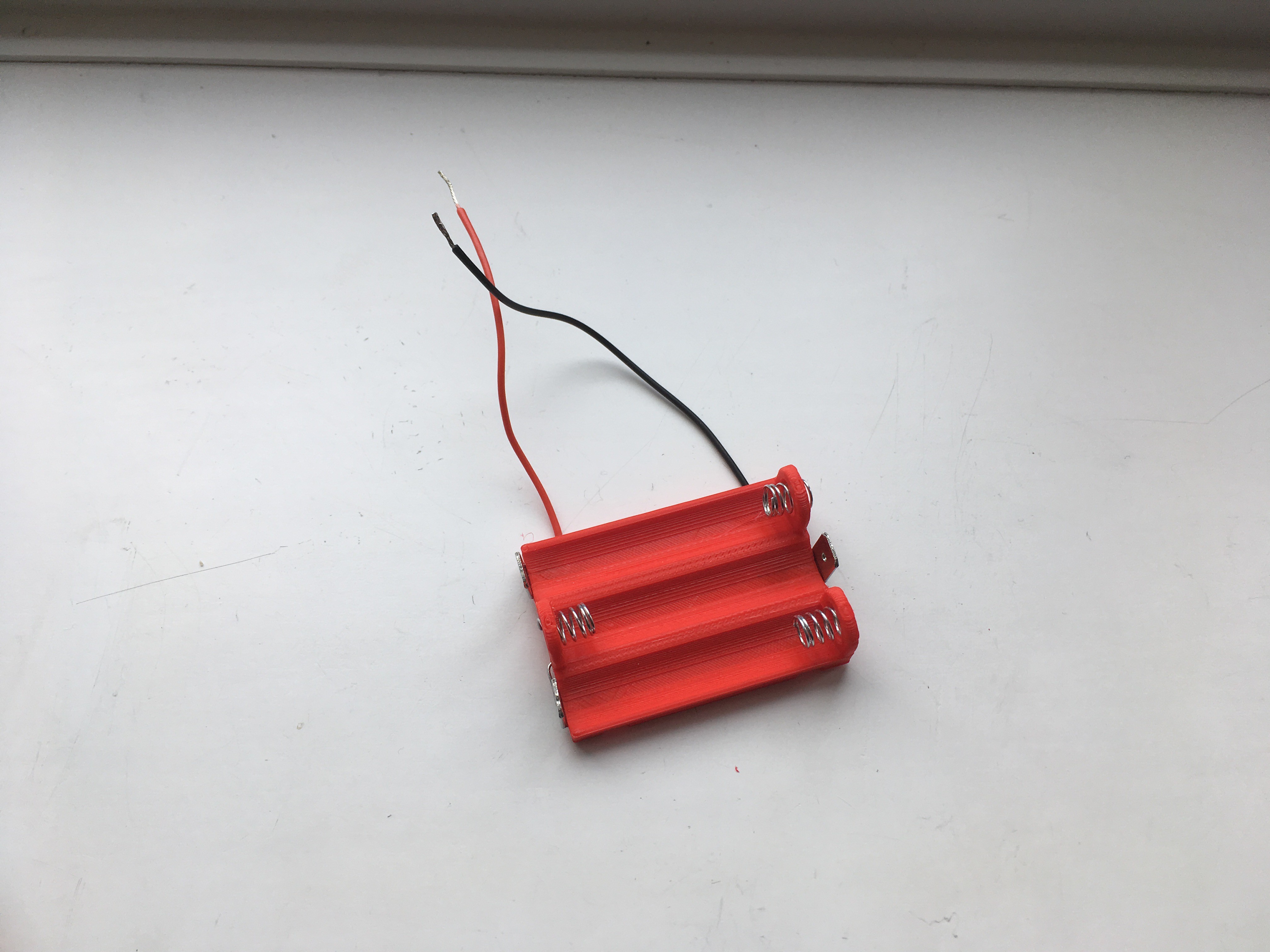
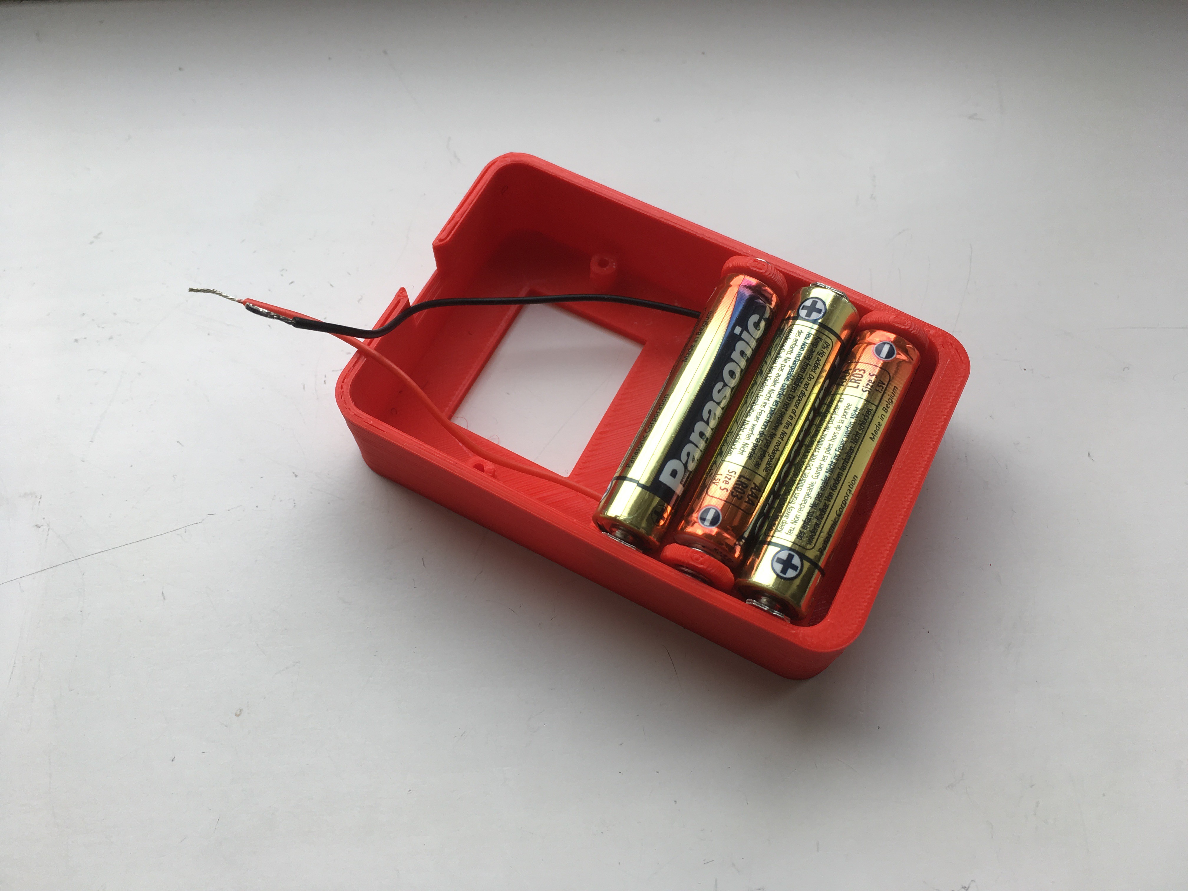
    Over the last week or so I've been working on how I'm going to power this project. The two options that I could have chosen are standard alkaline batteries or a LiPo and charger and for the sake of simplicity and cost I've decided to go for alkaline batteries. My tests have shown that three AAA cells should give a few hours of run time so I've been working on a battery holder. Here it is:

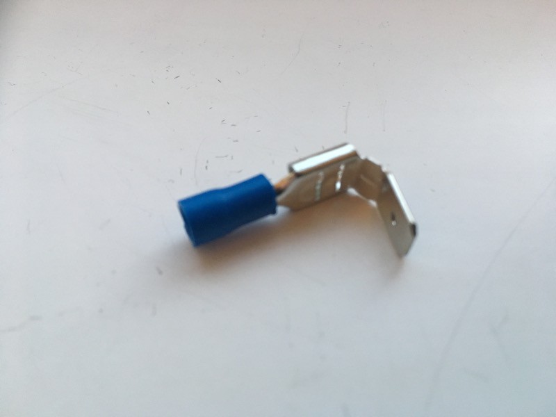
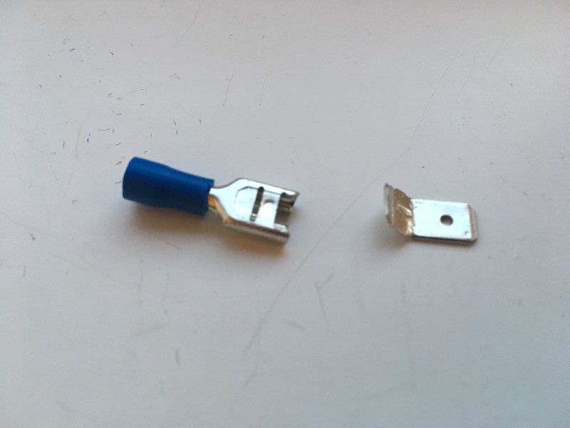
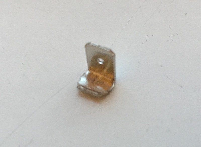
    The positive terminals are made out of the end of a stackable spade connector:


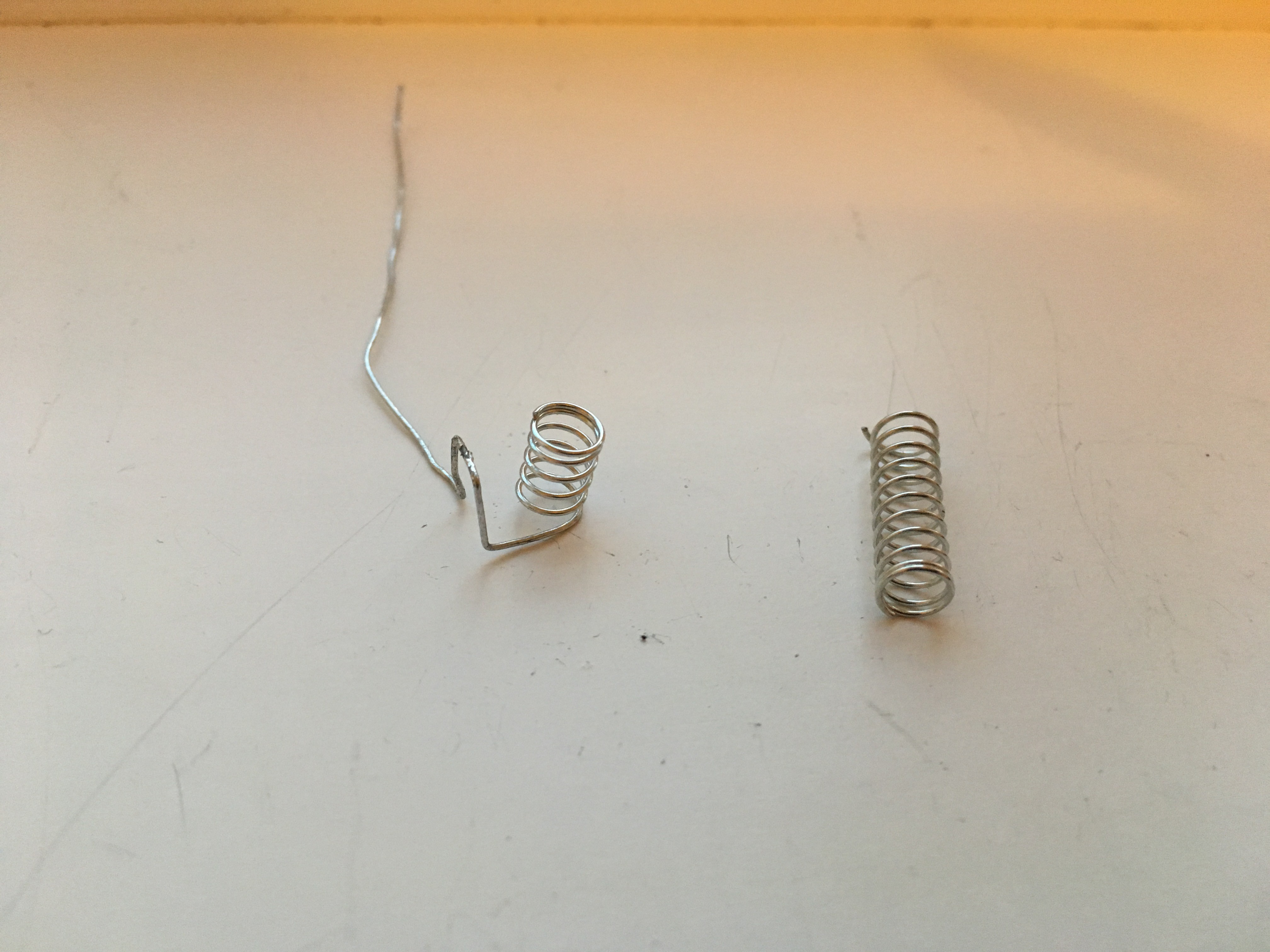
    The negative terminals are simply cut down springs:

    Both types of terminal slot into recesses in the base of the printed part after being soldered together. The outer case stops the terminals from moving outwards. This is roughly what it will look line in the case:

    I've had to make the case slightly wider to accommodate the holder but I'm still within my credit card sized footprint with 1mm to spare on the width.

  • #10 - First Light

    David Boucher09/06/2017 at 18:58 0 comments

    I now have the graphics library working:

    Currently supported graphics primitives are individual pixels, lines, and filled and unfilled rectangles, circles and triangles. I will probably add a few more primitives and also sprite handling.

    Back to hardware next: moving things from breadboard to finished article!

View all 19 project logs

Enjoy this project?

Share

Discussions

Michael Finley wrote 02/17/2021 at 12:28 point

We got this for one of our clinics and our waiting patients enjoy using it while they wait for their turn. Our services can be found here: https://albanychirocare.com

  Are you sure? yes | no

Vishnu Mohanan wrote 05/01/2018 at 08:15 point

I like the minimalist enclosure design :)

  Are you sure? yes | no

Similar Projects

Does this project spark your interest?

Become a member to follow this project and never miss any updates