Close
0%
0%

Desktop CNC Mill

A small CNC mill using a Dremel and as much stuff as possible from the local hardware store.

Similar projects worth following

Introduction

This was my starting point: Easy to Build Desk Top 3 Axis CNC Milling Machine by Tom McGuire. However polycarbonate seemed expensive for a project that I might never finish and I couldn't find steel pipe for the stand so I decided to use MDF for the support structure and platforms. Once I starting putting bits together I quickly realised that self-tapping screws don't work in MDF so lots of things had to change.

The machine is built and working but isn't finished yet. There are many enhancements and improvements I'd like to make. Now that I have a milling machine I can make better bits for my milling machine.

The overall dimensions are 350mm x 450mm x 400mm high. The table is 150mm x 150mm.

Control Software

  • Universal-G-Code-Sender on a PC as the human interface for Grbl (see below). It lets me jog the machine in any direction, send Gcode files, etc.
  • Grbl is software loaded onto an Arduino Uno which accepts Gcode and controls 3 Big Easy Driver boards each connected to a stepper motor on the milling machine.

Control Electronics

Here is a picture of the control electronics as they currently stand:
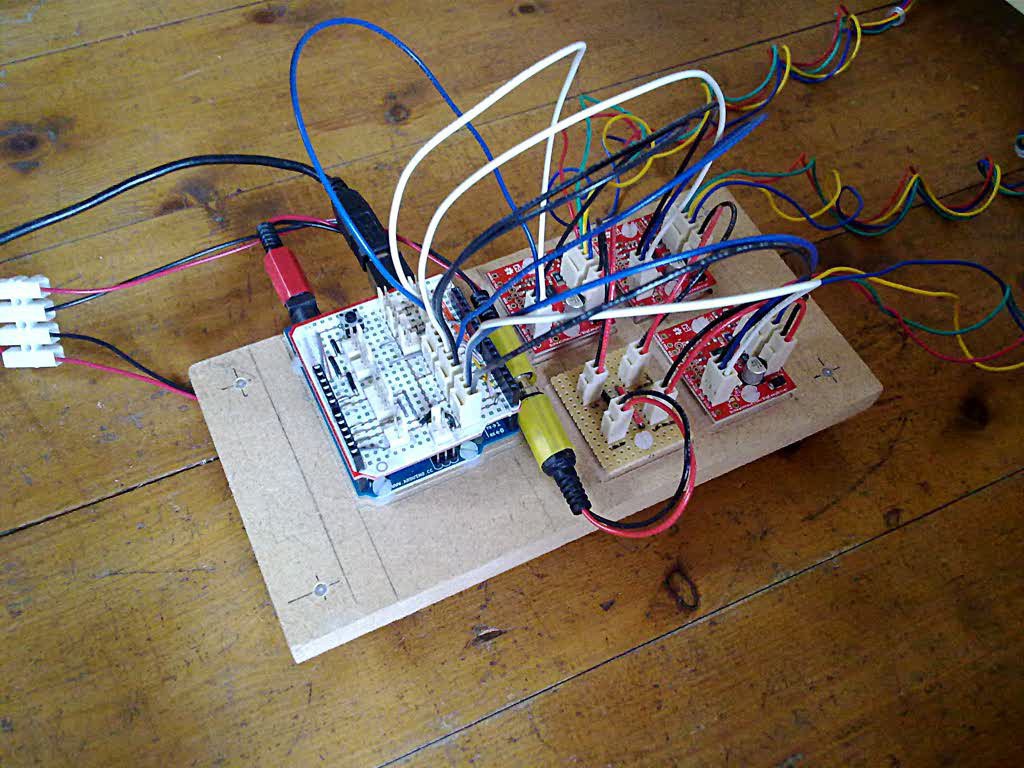
On top of the Arduino Uno is a Proto-Pic Breadboard Shield which breaks out most of the useful Grbl control signals. I'm only using the 3 stepper driver outputs at the moment but limit switches, start, hold, abort, spindle and coolant controls are there for the future.

The 3 red boards are the Big Easy Driver boards and the square strip-board simply distributes power to each of them.

The I/O cables are probably obvious:

  • USB cable from the PC transmits Gcode statements from the Universal-G-code-Sender software.
  • The barrel connector with the red tape supplies 5V to the Arduino.
  • The barrel connector with the yellow tape supplies 12V to the driver boards.
  • The 3 sets of 4 multi-coloured wires go directly to the 3 stepper motors.
Grbl_Shield.tar.gz

Eagle files for the Arduino Uno shield that breaks out various Grbl connections.

x-gzip - 39.05 kB - 09/28/2016 at 09:48

Download

  • 1 × Dremel 300
  • 1 × Sheet 12mm thick MDF Used for everything except the base and support structure.
  • 1 × Sheet 18mm thick MDF Used for the base and the support structure.
  • 1 × Aluminium channel bar 20mm x 20mm x 1.5mm x 2m The X, Y and Z platforms are supported by and slide on this stuff.
  • 1 × Aluminium channel bar 13mm x 10mm x 1.5mm x 2m The X, Y and Z platforms use this for guides.

View all 9 components

  • Project on Hold

    deadpangold04/04/2018 at 11:05 0 comments

    All work on this is on hold at the moment. I recently moved home and I'll be separated from the project by about 200 miles for a while. Necessary but frustrating.

  • A Better Clothes-Peg

    deadpangold04/16/2017 at 13:22 0 comments

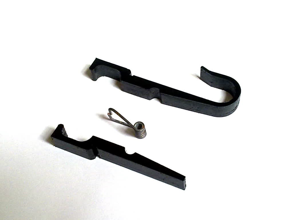
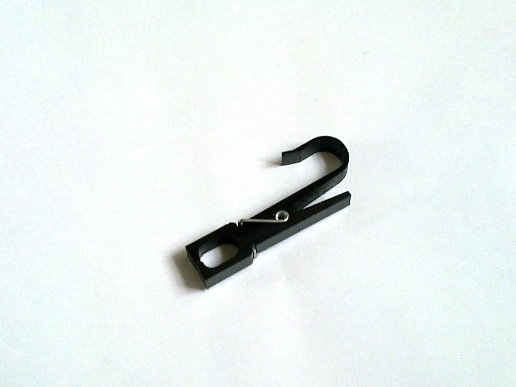
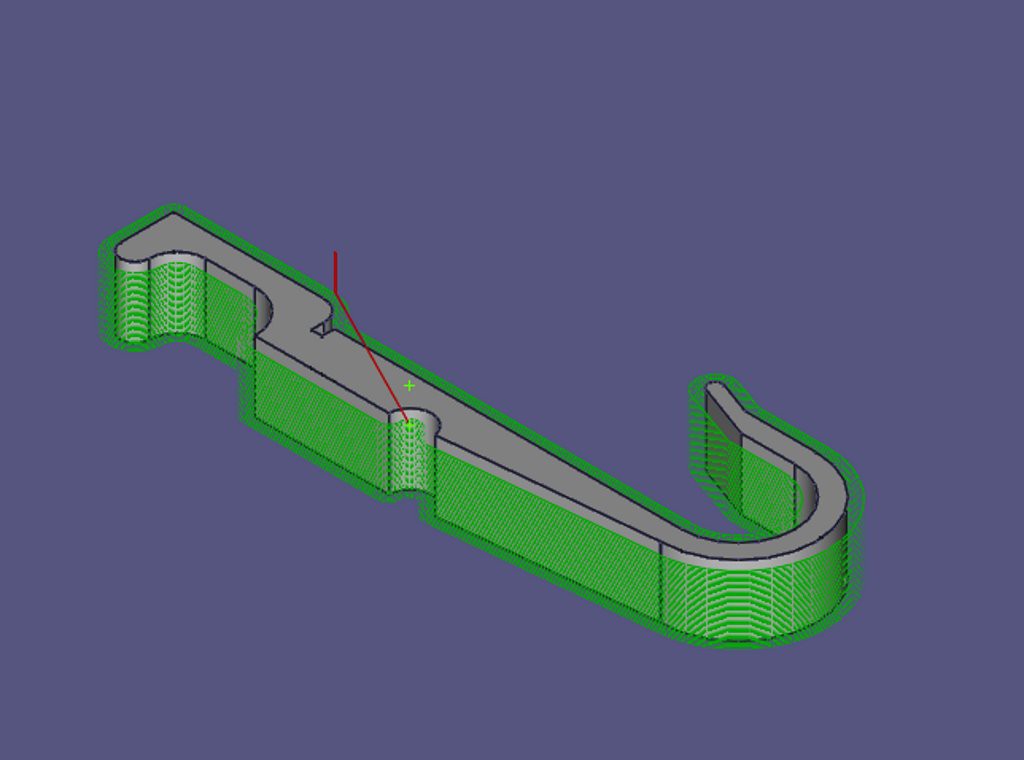
    I use clothes-pegs for lots of things other than for drying clothes. I've been making a few of these enhanced versions from HDPE. The design and toolpath generation was done with FreeCAD v0.16.

    I modified the jaws partly to increase the clamping pressure and partly because I could. The 20mm diameter hook was originally for hanging on a specific pipe but it has turned out to be a fairly useful generic size.

  • A Trackball Instead of a Mouse

    deadpangold12/04/2016 at 00:08 0 comments

    I've replaced my mouse with a Logitech Trackman Marble. I can now keep my eye on the cutter when I'm nudging it close to the work piece. I don't have to worry any more about the pointer drifting across the computer screen when I'm clicking the mouse. The mouse-pointer used to drift away from on-screen buttons and I had to be careful that a completely wrong button didn't get pressed. The trackball works a treat.

  • Improved Bearing-Holder

    deadpangold09/29/2016 at 21:31 0 comments

    Now that I have a milling machine I can improve my milling machine.

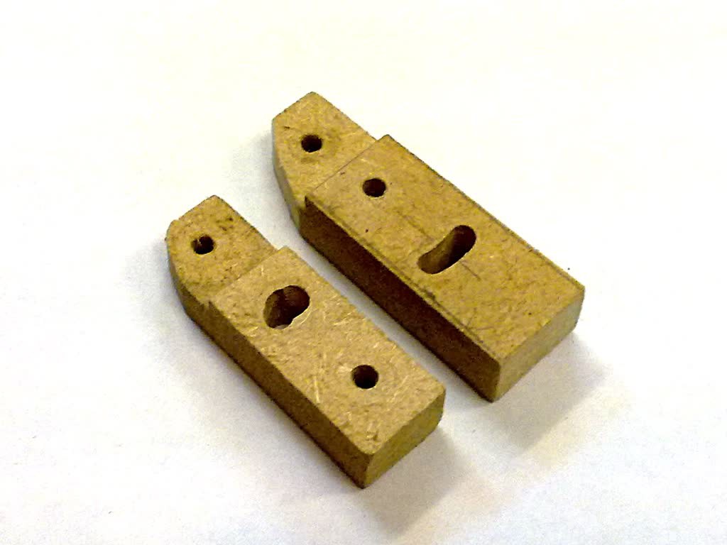
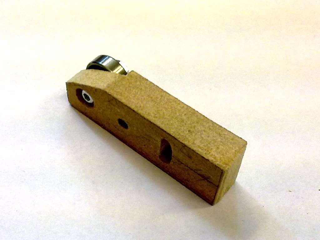
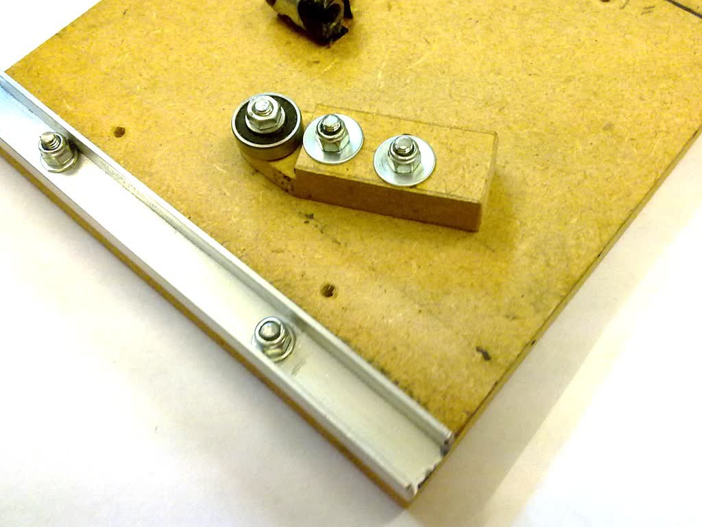
    From the start I've called this component "the bearing-holder". I couldn't think of a better name. It's a sort of lever-arm with a roller on the end that keeps two sliding channel sections together. There is one on each axis.

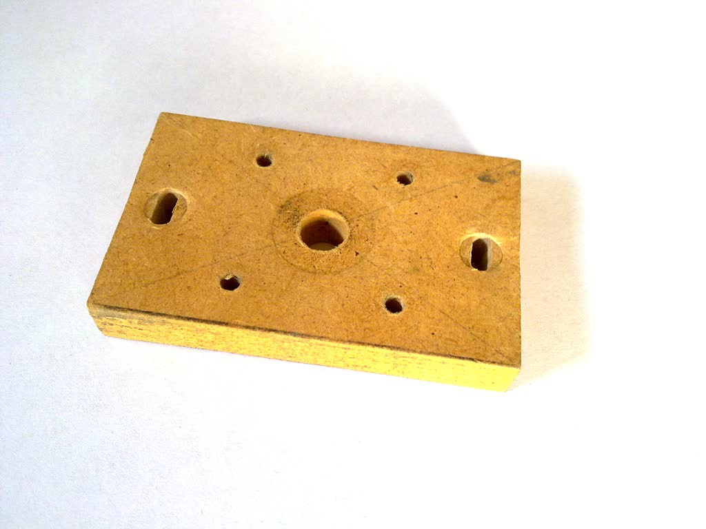
    The first picture below compares the old and the new. The old one is pretty bad. (It was the first and worst, I think.) It "features" a crude, curved slot that has been hand-cut in the least effective of the two positions. The new one is slightly wider, slightly longer and the curved slot is pretty good.

    Like much of this machine, this component is made from MDF (12mm thick in this case) but I don't think I'd use MDF for anything smaller. It just gets a little bit crumbly at that scale.

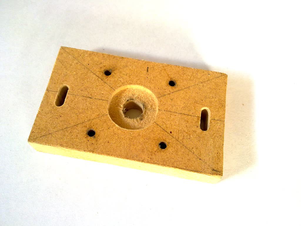
    The following photo shows the other side where the head of the screw that goes through the bearing needs to be recessed.

    And finally, here one in place on the underside of the Y-Platform. The 20mm aluminium channel section that I'm using determines the gap that this component has to fit into. There is not much left after 12mm of MDF, a washer and a nyloc nut.

  • Reducing the Cutter Speed

    deadpangold09/25/2016 at 23:15 2 comments

    I bought various thicknesses of HDPE recently and have been milling that. It looked to me that I was on the verge of melting the plastic instead of cutting it and I wanted to reduce the speed of the Dremel, but I was already on the slowest setting. I'm using a Dremel 300 which gives speeds from 10,000 to 33,000 rpm. To get some slower speeds I bought a Fan Speed Controller for less than £10. At very slow speeds the Dremel's speed gets a bit unsteady but away from that bottom end it all works just fine.

    I'm now wondering what cutting speed I am actually getting from the Dremel and how could I measure it. Some optical sensor connected to an Arduino with a 7-segment display perhaps. A home-made stroboscope perhaps.

  • Improved Motor Brackets

    deadpangold09/09/2016 at 16:16 0 comments

    Now that I have a milling machine I can improve my milling machine.

    The original MDF motor brackets that I made were pretty crude. The slots that I cut with a Dremel by hand took ages to do and I couldn't think of a reasonable way to cut the 2mm deep circular pocket to take the step on the mounting face of the motor. The slots ended up shorter than planned and the pocket got omitted altogether. Here is a photo of one I just removed.

    Note also the compression damage to the MDF, especially where the M4 bolts have gone through the slots. I'm in the process now of changing every washer that lies against MDF to a penny washer. That would have been a good idea from the start.

    I have now made and fitted new brackets with longer slots and a recessed pocket to better fit the motor.

  • More Hold-Down Points

    deadpangold09/09/2016 at 11:38 0 comments

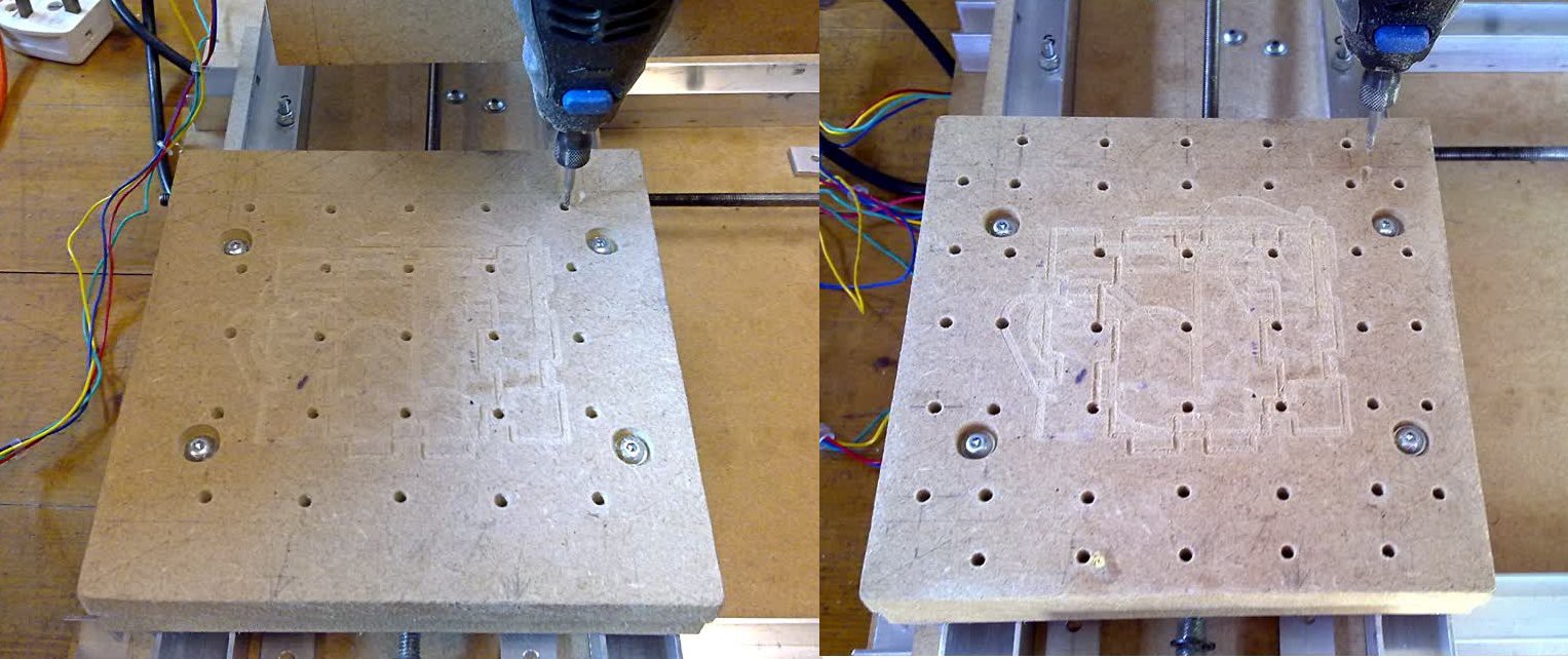
    It has been a while since I put anything here. Some time back I drilled and tapped some more hold-down points into the spoil-plate (M4). These have made it easier to clamp larger bits of material. The holes nearer the edge are much more useful than those in the middle.

  • Tabbed Enclosure

    deadpangold03/17/2016 at 23:04 0 comments

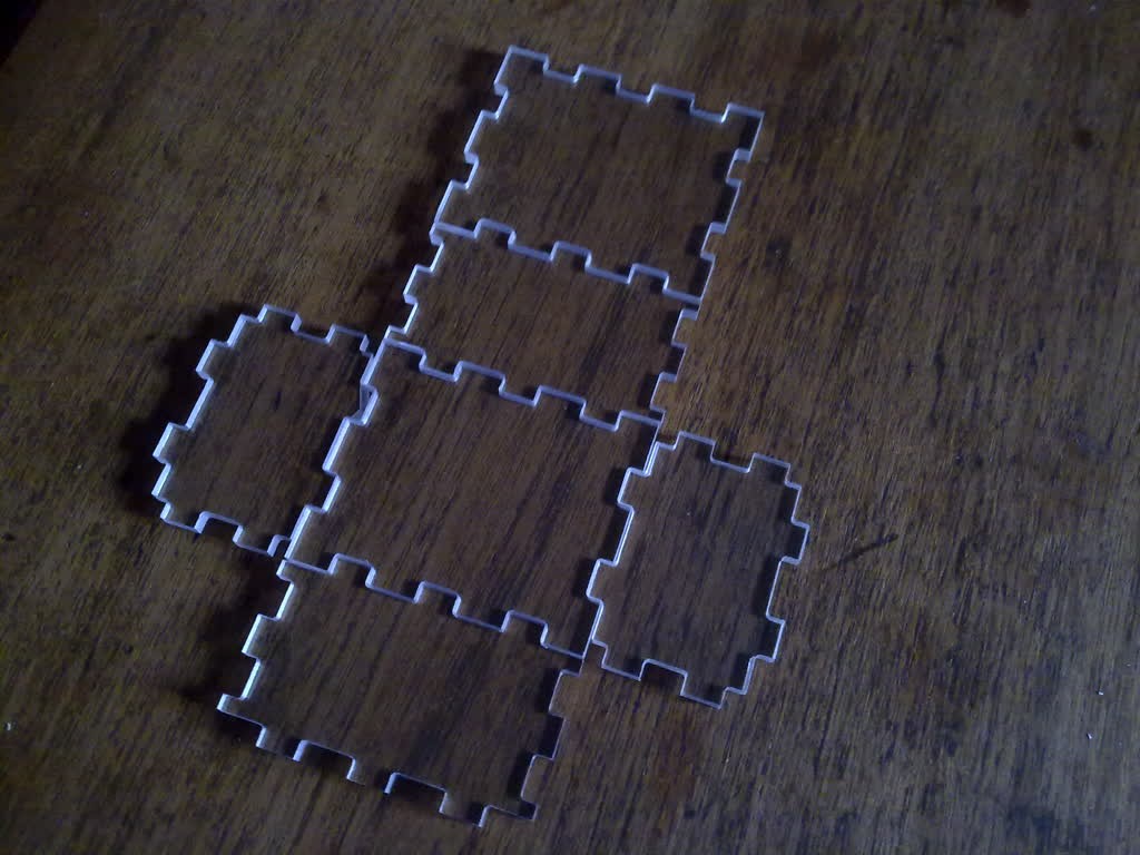
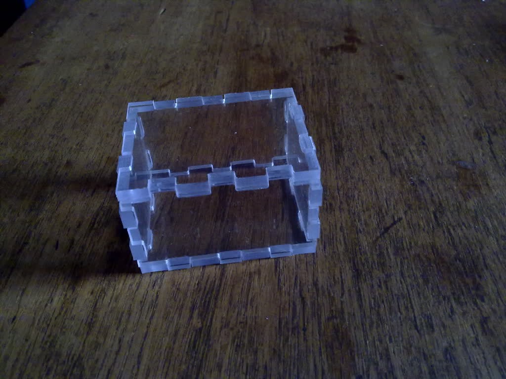
    I'd like the ability to make bespoke enclosures for my circuits, etc. Using the Tabbed Box Maker extension for Inkscape, I've milled this box for an Arduino Uno and shield. I haven't glued it yet though. It is all just balancing there and looks slacker than it really is. I need to cut some holes for I/O, power, etc. while it is still a flat-pack.

    Cutting these joints with the material flat on the bed produces inside corners that can be no sharper than the diameter of the cutter. I was interested to see how much of a problem that was in practice. I'm pleasantly surprised. I might sharpen the corners with a file or I might not bother. There might be a better way here: Perfect Box Joints - on a Small CNC

    It took ages to mill the 6 sides so I'm not sure if this is a realistic way to make bespoke enclosures. I'm very pleased with the first prototype though.

    Hackaday Article: http://hackaday.com/2012/07/26/box-maker-extension-for-inkscape/

  • Letter A

    deadpangold11/26/2015 at 10:16 0 comments

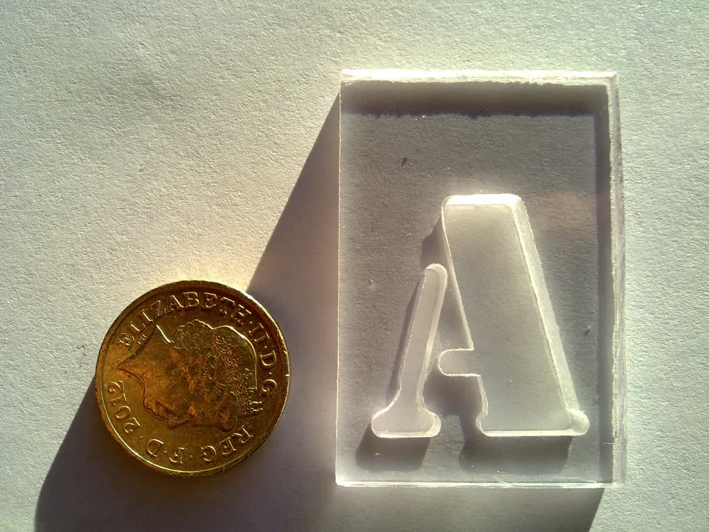
    I thought I'd try letter-cutting on a bit of scrap polycarbonate. In case it isn't clear, this is a full-depth cut.

  • Made a Shower-Screen Hook

    deadpangold11/25/2015 at 23:02 0 comments

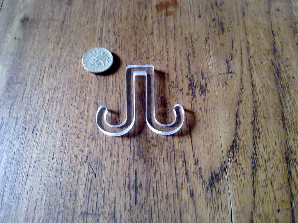
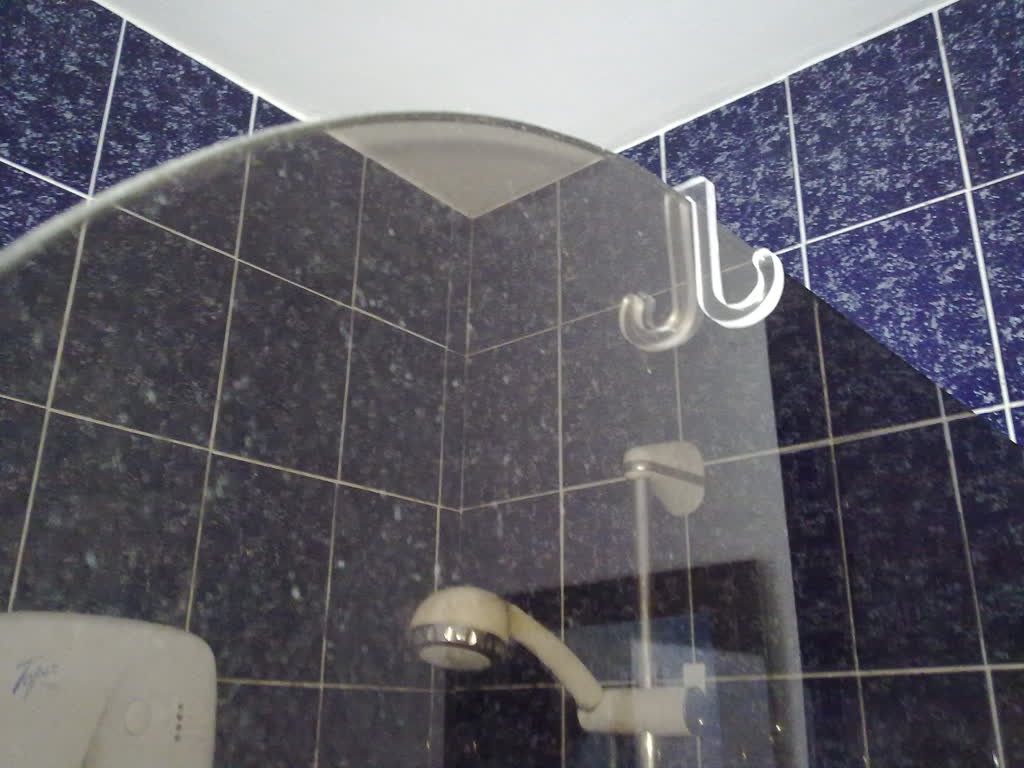
    I made this hook a while back too. (There is a theme developing here.) This one is for hanging wet gear on the shower-screen to drip dry.

View all 14 project logs

  • 1
    Step 1

    This machine was built, although not finished, before I started writing this. The following instructions are details of the build in no particular order - just when I think of them.


    Couplings


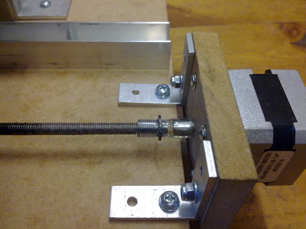
    One of my design goals was to use as much as possible from the local hardware shop. The couplings between the stepper motors and the drive screws are just short lengths of plastic tubing.


    The stepper motor shafts are 5mm diameter and the drives screws are 6mm diameter. Initially I used just a single length of tubing that I pushed on to each after first heating in boiling water. This seemed fine at first and the flexible connection meant I didn't have to worry too much about aligning the motor and drive screw. I only had the X and Y platforms built at this stage.

    Some time later when I had the Z platform completed and the machine actually working I found the motors getting quite hot, softening the plastic tubing and allowing the Z platform to slip downwards on the motor shaft. To solve this I found some smaller diameter tubing and pushed this (with some difficulty) onto just the motor shafts. The motor shafts were now effectively 6.5mm diameter. I then pushed the original coupling over the top of that (again with some difficulty).


    The next problem that arose was one of the drive screws would occasionally start to screw itself out of the tubing. This seemed to be a problem with just the X platform drive. Perhaps a little grease had got into that bit of tubing. To cure this I cut a small groove near the end of the drive screw, roughly the depth of the thread. Then, after pushing the tubing back on, I used a small e-clip as a retainer. I did this on all three couplings.


    Here is a photo of the current set up:

    X-axis coupling

    I've since found that the next size of e-clip fits snugly over the tubing on the now slightly larger motor shaft and I have one installed on the Z axis motor. It is still there, not because I needed it, but once I had pushed it on there didn't seem any point in removing it.

    These couplings haven't been as straightforward as I had imagined. I am quite pleased with what I have now though. I'm sure they will come apart if I push the cutting forces too high but actually that might be a good thing – a mechanical fuse.

View all instructions

Enjoy this project?

Share

Discussions

adam wrote 07/21/2021 at 07:12 point

Amazing! I love the idea, I will try this one. http://waterrestorationnashvilletn.com/

  Are you sure? yes | no

biały wygrywa wrote 07/03/2020 at 13:27 point

How creating a gcode for miling in cnc? 

for exampkle clamping but creating from wood, similar 3080 but on linux

  Are you sure? yes | no

lnxpeng wrote 09/27/2016 at 17:26 point

I think I might build one of these. What software are you using? And what CNC controller? I'm still stuck between an old computer with LinuxCNC or a hardware controller like tinyg.

  Are you sure? yes | no

deadpangold wrote 09/27/2016 at 20:21 point

Thanks for your interest and apologies for not having much about the build process here. If you want to build something like this I'm happy to help by posting more information as and when. Just ask.

I've just entered something under the "Details" section of this project about control software. Thanks for the stimulus. I'm using Grbl on an Arduino Uno as the CNC controller and Universal-G-Code-Sender on a Linux PC as the human interface. They were dead easy to set up. I have a photo of the electronics somewhere. I'll upload it when I find it.

I'm not sure if you are asking about other software too. When I started thinking seriously about building this milling machine I began using OpenSCAD to visualise it. I wanted the ability to document my thoughts in the same way as adding comments to a program. Eventually the physical build got ahead of the visualisation. I could upload a few OpenSCAD files if they might be useful.


  Are you sure? yes | no

Adam Fabio wrote 09/26/2016 at 04:20 point

Hey [deadpangold] You're a featured project on the Hackaday front page! Congrats!

  Are you sure? yes | no

joekutz wrote 11/27/2015 at 12:14 point

Your test cuts into acrylic look good - what cutting tool did you use? I tried a wood-cutting endmill for acrylic with my machine and ended up with blobs of molten plastic ;)

Looking as well forward to see your machine in action (for the case you plan to show it on YT)

  Are you sure? yes | no

deadpangold wrote 11/27/2015 at 15:20 point

I seem to be settling on the following cutters for cutting out shapes in plastic and MDF.

Dremel High Speed Cutter No193. Cutter dia=2.0mm, Cutting depth=6mm, Shank dia=3.2mm.

Dremel High Speed Cutter No194. Cutter dia=3.2mm Cutting depth=6mm, Shank dia=3.2mm.

I'll use a No193 if I am not going deeper than 6mm and the No194 if I am.

The first bit of plastic I tried to cut was an old red chopping board from the kitchen and it machined really well. So I bought a white chopping board from the supermarket. It was rubbish! As you describe, molten plastic would build up on the cutter and it would progress by melting, not cutting. I found that reducing the spindle rotation speed and increasing the feed rate helped but it was never reliable. What remains of the white chopping board now hangs in the kitchen. Choice of material is more difficult than it first seemed.

Specifically, the polycarbonate I am using now is labelled "Lexan 9030" (http://sfs.sabic.eu/product/lexan-solid-sheet/general-purpose/). I need to find alternatives that will give a choice of colours and stiffness.

  Are you sure? yes | no

deadpangold wrote 11/28/2015 at 22:18 point

I should also mention that I'm milling this Lexan with an incremental cutting depth of 0.25mm and a feed rate of 70mm/min (A bit less for the bigger cutter). I suspect these figures will seem fairly conservative.

  Are you sure? yes | no

joekutz wrote 11/29/2015 at 10:57 point

Ah I see, yea, tried something similar. I was cutting acrylic'ish plastic with my selfmade 1mm cutter (made from a sewing needle) and also found that using small steps (I used 0.5mm) make things more save. 70mm/min is very low, I think you could easily get up to 120-150mm / sec, especially when you just cut 0.25mm in a go.

  Are you sure? yes | no

deadpangold wrote 12/18/2015 at 21:42 point

"I think you could easily get up to 120-150mm / sec, especially when you just cut 0.25mm in a go. " 

I'm doing things carefully as I don't have bearings on my machine to take the cutting forces.

  Are you sure? yes | no

Michael Vowles wrote 11/26/2015 at 00:57 point

looks good mate would love to see a video of it in action. What kind of accuracy are you getting out of it? 

  Are you sure? yes | no

deadpangold wrote 11/26/2015 at 09:54 point

"What kind of accuracy are you getting...". Good question. I keep telling myself to stop making things and do some serious stuff like measure accuracy, backlash, etc. In a way it doesn't matter - if the things I make are accurate enough that's fine - if not I'll try to improve something.

  Are you sure? yes | no

Michael Vowles wrote 11/26/2015 at 13:24 point

fair enough mate, I've been thinking about doing something like this is with my dremel. I think it would be incredibly useful. 

  Are you sure? yes | no

Similar Projects

Does this project spark your interest?

Become a member to follow this project and never miss any updates