Close
0%
0%

Roboartist

"Can a robot turn a... canvas into a beautiful masterpiece?" - Will Smith (I, Robot)

Similar projects worth following
Remember that scene from I, Robot where super-bot Sonny sketches his dream to Will Smith and Bridget Moynahan? Well, screw the future... Lets do that kinda thing TODAY!

Although Roboartist can't dream on his own, he's pretty good at drawing whatever you throw at him. Show him that picture you took on that trip you went on the other day, and watch him grab a pen and swing into action.

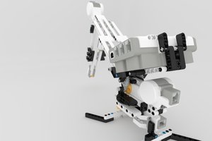
Roboartist is a 4 stage robotic arm that can sketch out the outline of any image using a pen/pencil on an A3 sheet using Edgestract, our custom made edge detection algorithm. The project relies on the core engine to extract the edge from the image uploaded for processing. An Arduino Mega controls the servos using information sent from MATLAB (Fret not, a more open implementation is on the way) via the USB/Bluetooth port.


THE HARDWARE
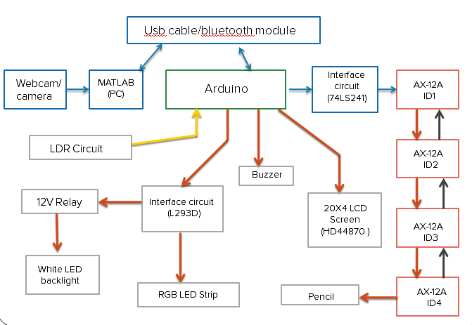
Hardware Layout

The basic layout of the hardware is as above. Image acquisition is achieved through a Webcam or a camera. We've also allowed scanning of existing JPEGs. Although an RGB LED strip and an LCD Screen weren't strictly necessary, we threw it in just for fun. What does really improve the product design is the white LED backlight constructed from LED strips. The light diffuses through the paper, providing a nice aura to the performances of the Roboartist.

THE SOFTWARE
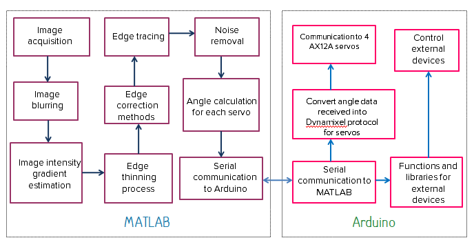
Software structure

Here's how the software is structured. The basic idea is to let MATLAB do all the heavy lifting and let Arduino focus on wielding the pencil. The program requires the user to control a few parameters to eek out the noise and obtain a good edge output. Once finished the program communicates with the Arduino (via Bluetooth, 'cos too many wires are not cool!).

STAGES

Here is a quick peek at the image processing stages involved:
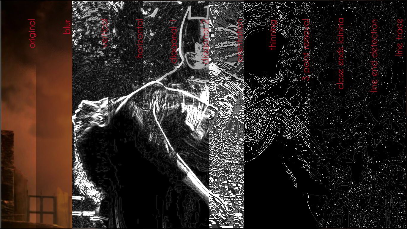
Each slice is from a consecutive series of DIP stage. We've been using the Canny edge detection algorithm initially, but we've now built and switched to Edgestract, a more optimized algorithm for drawing. We have been running the algorithm over various types of images and logging the results.

We'll tell you more in the coming updates.

  • 1 × Arduino Mega Atmega 2560, 8 bit microcontroller
  • 1 × Laptop / Computer We got an eye on the Pi ;)
  • 4 × AX-12 A Servo Motors Dynamixel with associated brackets, nuts and connecting cables
  • 1 × 20x4 LCD module based on HD44870 Display the angles and status real time.
  • 1 × 12V Relay Purely for backlight control

View all 11 components

  • New portrait drawing video! Yay!

    niazangels08/29/2015 at 15:52 0 comments

    Hey everyone,

    It's been a while since we've posted. Something came up and so we had to shoot another video of Roboartist drawing a portrait. We tried to show the whole process from start to finish. Here check it out:

    Also, we've ported the Matlab code base to Python and promptly forgot to toot our horn. We'll do that some other time. But for now, the interface is much more cleaner than it was before. We got kind of a retro feel smashed with smooth transitions.

    I kind of wish we had better lighting in the room. There are a few improvements we'd like to make too- if you have any, leave a comment below too.

    Until next time :)

  • Serial Communication on a Hacky Afternoon

    niazangels05/06/2014 at 10:04 0 comments

    This might be one of those things we probably did on a lazy afternoon. Or evening. I don't remember. Coming up with ideas when drowsy... Half asleep, half awake. When we got to our senses, we realised had a bunch of code that did the job well, but didn't exactly measure up to the International Coding Standards to Not Drive Developers Wild. But it worked. And we let it reside. Today, we introduce you to that part of the code that makes the actual drawings. If you haven't read up on how we managed to position our motors at the right places on the drawing sheet, you should probably read that first.

    Anyway, what's the easiest and laziest way to draw on paper then? Tell us if you come up with something lazier in the comments but, we sent the angle values of each AX-12A servo for drawing each pixel to the arduino at rapid rates. Seriously. That's it. This resulted in the stylus moving in the transformed direction of the pixel currently being traced. Here's how we sent the signals to the Arduino.

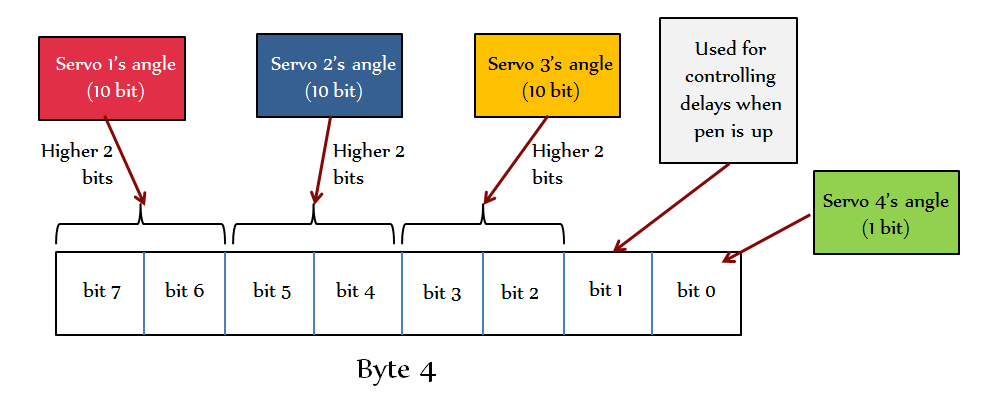
    For controlling the first 3 servos we need 10 bits- ( 0-1023 since Dynamixel AX-12A motors provide 300 degrees of rotation over 1023 steps ) and the 4th servo only needs 1 byte to represent up/down. Hence a total of 31 bits ( nearly 4 bytes) must be sent for representing each pixel. But since arduino supports only 8 bit serial data we break down and rearrange the bits as follows:

    The first 3 bytes are formed from the lower 8 bits of the servo angle values. The 4th byte is formed from the upper 2 bits of the 3 servo angles, a delay control bit and the bit representing servo 4’s angle as shown above. These 4 bytes together represent a single point of the image to be drawn on the paper. These bytes are then sent to the Arduino in clusters of 32 bytes

    Arduino microcontrollers supports standard baud rates: 4800, 9600, 19200, 38400, 57600, 115200. The Arduino Mega has a 64 byte serial register for incoming bytes. MATLAB initially sends 64 bytes worth of data to the Mega. In the consecutive cycles, after the Mega reads 32 bytes of data, it sends a signaling byte to MATLAB requesting the next 32 bytes. During this time the Mega can read the remaining 32 bytes and hence there is no delay by waiting. We just needed to rearrange the bits on the other side and fire it away to the motors. The signaling byte we have chosen ( for no apparent reason ) is 50 ( 0b00110010 ).

    Yup. That was hacky enough for one day. We probably spent the rest of that afternoon ringing doorbells of the neighbours and hiding in the bushes.

  • Edgestract - An 'uncanny' edge detection algorithm

    niazangels05/02/2014 at 21:19 0 comments

    Wow! There has been quite a lot of buzz about the Roboartist, last week and we even got to the pages of Hackaday.com, Engadget and Popular Mechanics. We're delighted and thankful for all the attention we're receiving. Let's just clear this one little thing that seems to be floating: We're not using the Canny Edge detection. We were for a while. However things got messy pretty quick. Read on to find out what went wrong and how we beat it. It was a classic case of necessity spawning a solution.

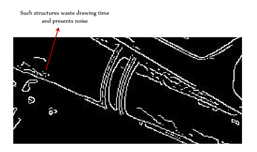
    The output of Canny filter gives emphasis to the individual gradient around each pixel separately in determining if the pixel should be an edge or not. However, it does not include the length of a structure formed from a group of adjacent pixels, so structures the length of only a few pixels show up as edges. This is not really good news for Roboartist because it means he'll be spending a lot of time poking on the drawing sheet ; messing up the good renderings and annoyingly taking up a lot of time on that ( yup, happened ).


    We are clearly better off with an algorithm that evaluates the length of each structure and then along with the sum of the gradients at each pixel determines whether the structure as a whole is classified as an edge or not. And that's exactly what we built. Edgestract.

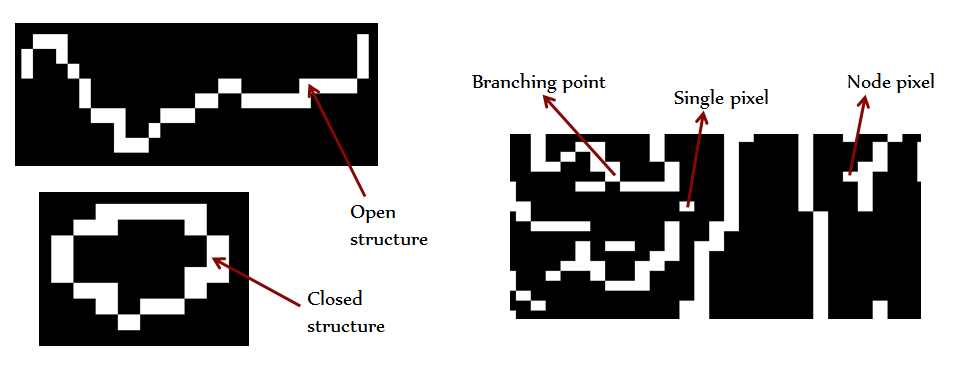
    Ok, so how do we find out the length of each structure for this? We correct all forks and branches in all the individual structures until only perfectly open structures or perfectly closed structures remain.


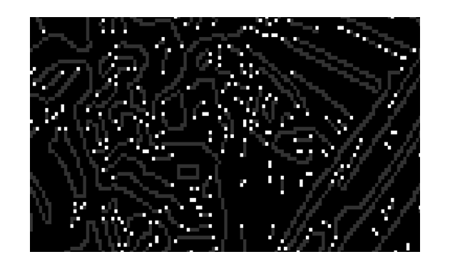
    In the above stage, all branches and nodes are removed and only selected open and closed structures remain. We've also marked all the endpoints on all open structures as shown. We're now good to perform structure the tracing process!

    First open structures are evaluated: we start from one end of an open structure and we move to the next adjacent pixels one by one and increment length variable by 1 for each pixel transversed. When we reach the other end point we get the total length of that structure. We then search and jump over to the end point of the closest surrounding open structure. To prevent the same structures from being infinitely traced by this process we delete each pixel information as we trace along it.

    Ultimately we get the lengths of each open structure and all of them are deleted. The information regarding the path we traced and the length of each open structure is stored. We then repeat this process for closed structures, starting from any point on a loop structure (since loops don't have end points) and after covering a complete loop, jump to the nearest point of another closed structure. All the length and path information is combined with the earlier data. We can now select edges from the individual structures knowing the length of the structure from the tracing process and  combining that information with the path taken by it. The path gives info about all pixels covered by that structure, hence the sum of gradients of all pixels obtained.

    Check out the following image.


    We've superimposed the edge results onto the main image. You'll find all the tiny structures get rejected as their lengths are too small. This could easily backfire, but by carefully controlling a few parameters, you can reduce the noise involved. Hence image appears neater and duration for drawing is reduced. Edgestract is optimised to churn out 'drawable' images. Through the tests we've put it through, it was found that it gave us significantly lesser headaches. 


    Edgestract : saving the world before drawing time :)

  • Motor Angle Calculation Breakdown

    niazangels05/01/2014 at 15:42 1 comment

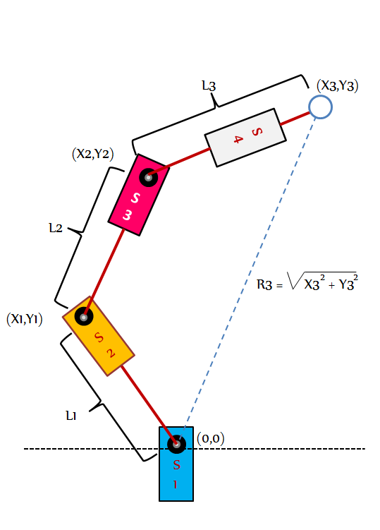
    We thought you might be interested in knowing the mechanics and math involved in four stage arm control. Its quite simple really. We hope this will help a few new hackers with their future builds. Here we go...

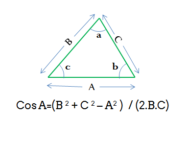
    The aim of this algorithm is to determine the angles that the servos should take for the robotic arm holding the pen to be positioned at (X3,Y3). We perform the calculations in the Cartesian coordinate system by taking the axis of servo S1 as the origin. The following little formula you've probably learnt (and forgot) will come in handy. Its refered to as the Law of cosines.

    We start by assuming we know (X1,Y1). 

    S4 servos angle does not need to be calculated as it is only needed for lifting and placing the pen on the paper. We can therefore ignore it in this derivation. 

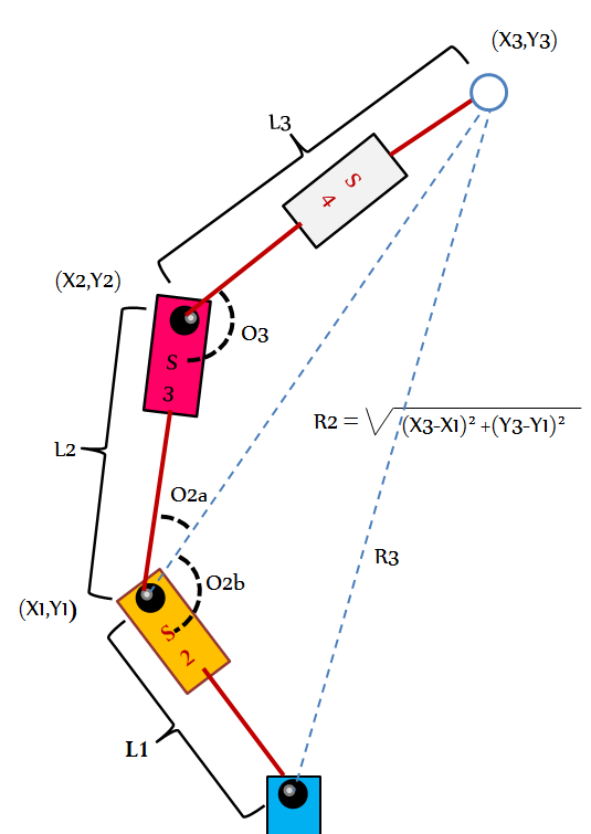
    Since L1, L2 and now R2 is known, by using equation we find the angle to be moved by servo 3 (O3).

     O3 = Arccos ( ( L2^2 + L3^2 - R2^2 ) / (2.L2.L3) )

    Similarly, we find O2a and O2b as marked in figure. Adding O2a and O2b, we get the angle O2 to be moved by servo 2.

    O2a = Arccos ( ( L2^2 + R2^2 - L3^2) / (2 . L2 . R2) )

    O2a = Arccos ( ( L1^2 + R2^2 - R3^2) / (2 . L1 . R2) )

    So we can sum up those angles to find out angle O2.

    O2 = O2a + O2b

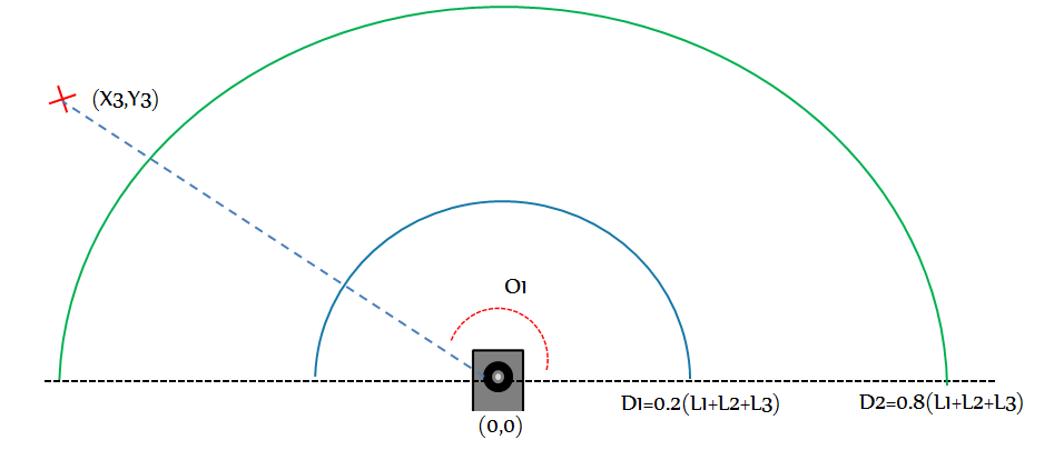
    Great! But we still don't know the value of O1 . This one's a little tricky, take a look at the following figure. We've divided the drawing canvas into three regions.

    • If the point to be drawn is further than D1 from the origin (as shown), then O1 = Arctan ( y/x ).
    • If the point to be drawn is nearer than D2 from the origin, then O1=Arctan ( y/x ) + pi/2.
    • If the point to be drawn is nearer than D21 from the origin but farther than D1, then O1 = Arctan( y/x )+( pi/2 ).( D2 - R3 ) / ( D3 - D2 ).

    Now that we've deduced O1, we can derive points ( X1, Y1 ) using 

    X1 = L1 . Cos( O1 )    and    Y1 = L1 . Sin( O1 ).

    There! That wasn't so hard, was it? Next time we'll try to give you some insight into the algorithm that processes the images.

  • Video 0x01

    niazangels04/28/2014 at 11:30 0 comments


    Just finished stitching and synchronising the video. We tried to give you a close up of the rig. If you need a birds eye view of the entire drawing process, we'll be happy to jack up a cam on a tripod and have it capture it for you. 

    And while we're at it, we'd like to thank you guys for all the support we're receiving. Don't forget to let us know where we can improve. 

    Signing out.

  • Lighting hacked to reflect completion

    niazangels04/27/2014 at 09:26 0 comments

    Remember the RGB LED we put on the side? We thought it'd be a great idea if it could somehow indicate the percentage completion of the drawing instead of randomly fading between the colors. So we tweaked our code again and this is how it works now:

    Awaiting input :  Breathing blue lights

    Drawing  [0 % = RGB (255,0,0) ]  ------ [Transition] -----> [100 % = RGB(0,255,0)]

    pure red                                                          pure green

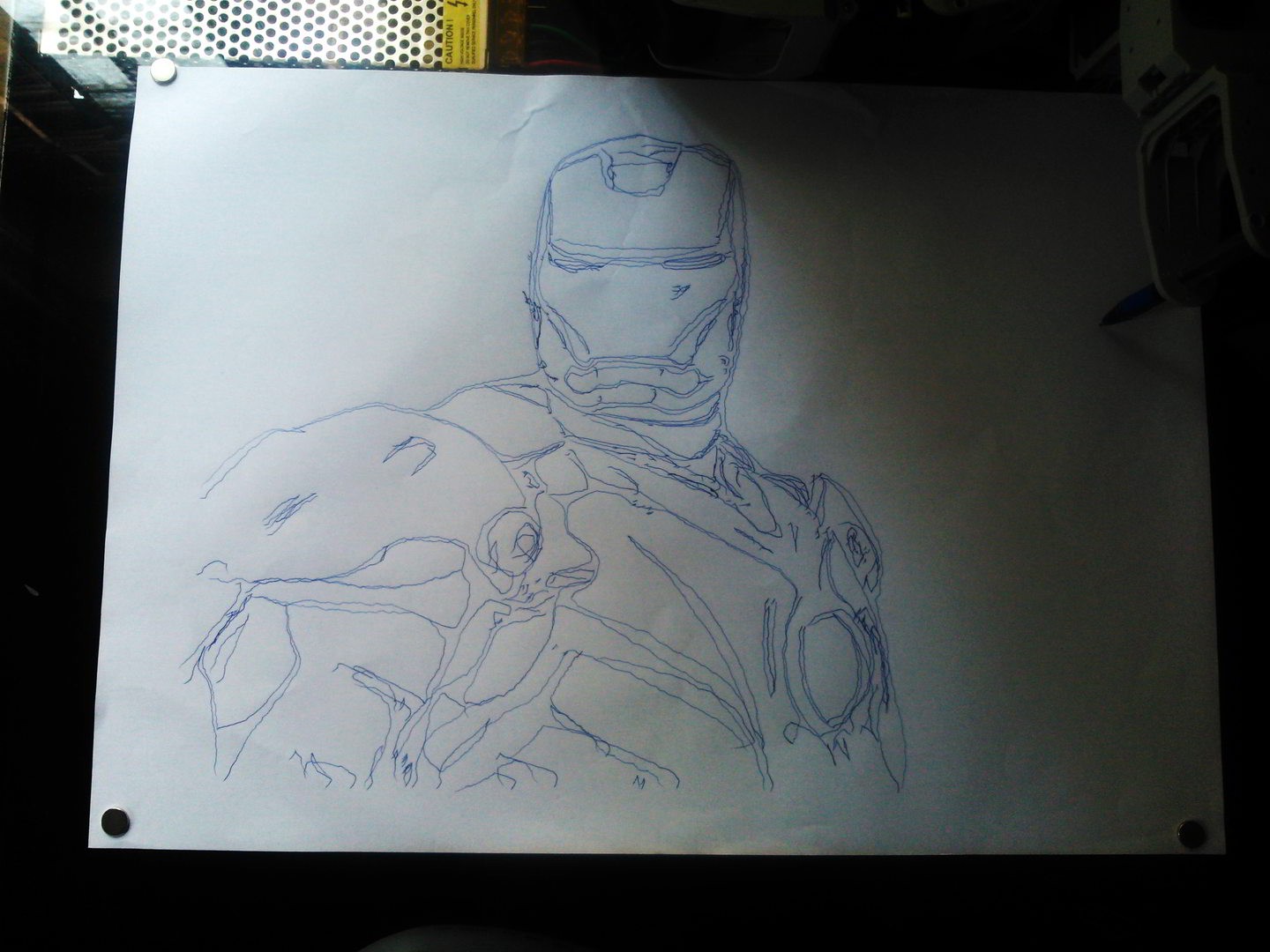
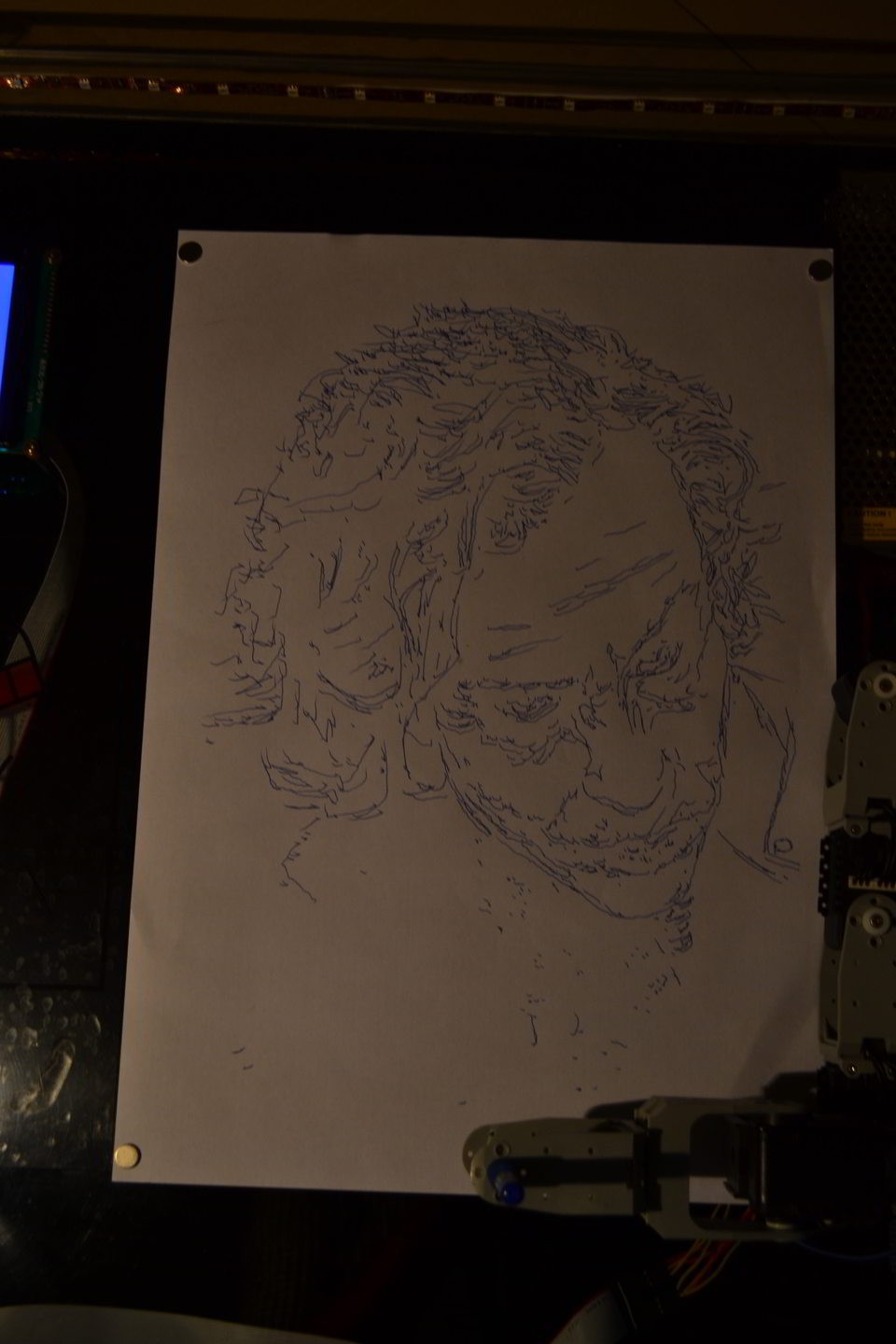
    It looks great when we tested out Ironman! But we forgot to capture the pics until we finished. We shot a new Joker video and its under processing. It should be out tomorrow. 

    In the meantime, have you checked out the incredible Animatronic Iron Man MKIII suit yet?

  • Images (of XOR from) Roboartist

    niazangels04/25/2014 at 13:30 0 comments

    We got our pics taken yesterday, and everything that could have gone wrong did go wrong; but that's a story for another night. But check out the first releases of the images sketched by the Roboartist. Although we've been having him drawing images for weeks, this is one of the very best sketches we've had. Check out the detail on this one:

    We'll be posting more pics in the course of the week, in the meantime, we would LOVE to hear from you! Leave us a message and tell us what you think!

  • Stickers, photos & revelation

    niazangels04/23/2014 at 16:07 0 comments

    One of the prime reasons we haven't posted any photographs of the Roboartist is because we wanted to do it right. We planned to show the world a finished product. We're really excited to tell you that we'll be revealing the Roboartist in his full glory tomorrow night. We thought you might appreciate something better than our amature photography skills so we're having our friend [ Athul Raj ] come over and shoot some really nice pictures for you. So hold up one more day.

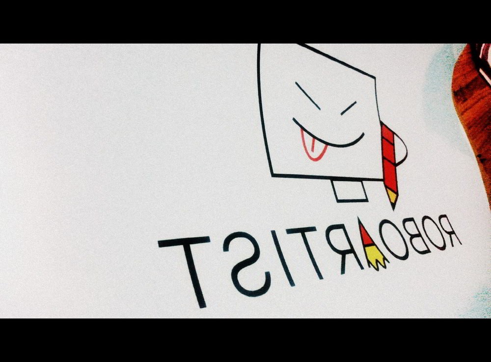
    Over the last few weeks we've been tweaking our designs and today we've proud to announce that we've finally got the stickers straight off the printers'. Here, take a look :)

    Brand new Roboartist stickers!

    Some of you are probably wondering why its laterally inverted, and the answer to that is because the sticker will go on the underside of the top acrylic base. That means it'll be protected from wear and tear of the outside world. Also it'll be faintly visible on the A3 paper that is being sketched on when the backlight is fully lit. 

    Photos are nice, but a video is even cooler, right? We've got that covered as well. Stay tuned to find out. Oh, and tell us what you think of the stickers!

  • Let me bring you up to speed

    niazangels04/22/2014 at 19:18 0 comments

    Clearly, this is not an overnight project. We spent months turning caffeine to code and inhaled our fair share of rosin fumes. It all began in late October last year when we got together to discuss what project to take on next, switching through our sci-fi movie playlist , as we mostly do on every other weekend. That's around when awesome-bot Sonny took to screen and began his artwork. Now, we've seen I,Robot like a dozen times (like all good hackers should), but I guess that's the point where we really got thinking if that kind of thing was possible. A robot that draws pictures sounded pretty rad.

    We spent our next month doodling the blocks that we'd use to build Roboartist. After we had fixed on the design, we sourced parts from the rest of the Multiverse. Aside from the minor hiccups along the way (like the time our inter-galactic shipping got delayed by 3 weeks and a random guy who ran away with our Galactic Moon Coins) we were still steaming ahead with the plan. By the end of January, we had a working model.

    Prototypes are prototypes. And that meant though everything was working, there was still more to be done. We spent time modifying the algorithm for edge detection until we found a sufficiently good edge to noise ratio. Every good project deserves a case as good, so we re-worked the design to have an acrylic base. We got really funky and used Neodymium magnets to keep the paper in place. Tape would destroy the creation about to unfold on the sheet. Everything said and done we still needed a good place to showcase our work, and what better place than Hackaday, right?

    Over the next few days we'll put up build specs and possibly the code. Currently the core engine is coded in MATLAB (yes, hackers use MATLAB too, okay?). However, we're also porting the core to a more open platform for the Multiverse.

    Interested in finding out more? Stick with us :)

    P.S. You are now up to speed

View all 9 project logs

Enjoy this project?

Share

Discussions

jalibbaig wrote 08/08/2016 at 13:58 point

 How much did this project cost to u ? Thanks 

  Are you sure? yes | no

matt collingridge wrote 02/06/2016 at 03:17 point

I would totally use this to produce exam notes. well all the notes need to be hand written.

  Are you sure? yes | no

Serdar wrote 01/28/2015 at 18:38 point

I m sorry,but i didn' understand relationships between matlab and equation.Also, how can I use matlab with arduino?I want to do this project maybe you can help. (serdar.gulmes@hotmail.com)

  Are you sure? yes | no

niazangels wrote 04/12/2015 at 05:04 point

Hey serdar, MATLAB is used to create the final image that is drawn on the paper. Arduino does not pack the computational power to do this. Arduino and MATLAB talk to each other with via Serial communication. Look it up :)

  Are you sure? yes | no

Serdar wrote 04/12/2015 at 10:45 point

ok.thanks.well from where must i begin to do this?

  Are you sure? yes | no

Eric Hertz wrote 12/13/2014 at 00:39 point
edge-extraction and drawing machines go hand-in-hand... 's why my drawing-machine never took off. Nice algorithm!

  Are you sure? yes | no

Moritz Walter wrote 09/08/2014 at 16:01 point
Hey there! Is there any chance your robot could draw my project for use as "artist's redention" in the hackaday prize? It's the Hoverlay: https://hackaday.io/project/205-Hoverlay-II

  Are you sure? yes | no

bonpas3 wrote 07/04/2014 at 16:38 point
that 's great job Congrats

  Are you sure? yes | no

skyberrys wrote 05/01/2014 at 16:24 point
Hey this thing is really impressive. I would like to give a try at building one.

  Are you sure? yes | no

niazangels wrote 05/02/2014 at 21:27 point
Thanks, skyberry! We'd love to see you build. We hope to release everything you need to build your own and if that doesn't help, ping us and we'd love to pitch in.

  Are you sure? yes | no

Eric Evenchick wrote 04/30/2014 at 05:24 point
If you're looking for something more open than MATLAB to do edge detection, OpenCV has Canny detection built in. Not sure if it's sufficient for your applications, but the Python bindings make it pretty easy to get going.

  Are you sure? yes | no

niazangels wrote 05/01/2014 at 15:49 point
Thanks for the heads up, Eric, but we've tweaked the Canny beyond recognition at this point. While we do blur and scan in 6 directions, we've added stages such as Thinning and Single pixel elimination to create a reasonably drawable image. We'll try to post an entry explaining the process.

  Are you sure? yes | no

Eric Evenchick wrote 05/04/2014 at 08:03 point
Alright, looking forward to hearing more about the processing then.

  Are you sure? yes | no

niazangels wrote 05/05/2014 at 08:00 point

  Are you sure? yes | no

Similar Projects

Does this project spark your interest?

Become a member to follow this project and never miss any updates