Close
0%
0%

The Razor E300 Overvolt!

Building an electric scooter with some real power.

tkTK
Similar projects worth following
I bought a Razor E300 as I wanted to see what off-the-shelf electric scooters were like. They're alright, but they're let down by lead acid batteries. You get a scooter that's heavy and slow. I wanted speed! I decided to switch to lithium power using only what I had on me - and I had a lot of fun in the process!

I've been into electric scooters for a long time. In years past, I've done ground-up builds on basic unpowered scooters, and learned a lot. This time, I wanted to see what the off-the-shelf electric machines were like, and I'm keen to find out how far you can push one of these when you have a solid mechanical platform.

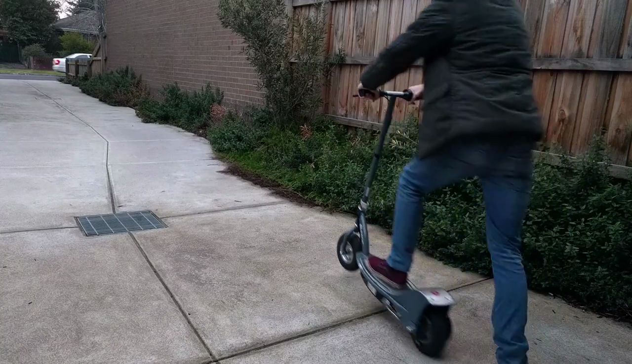
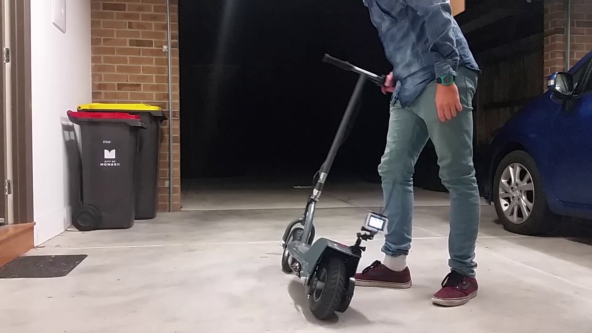
Me, mid-skid on the scooter. Skids are fun! #rearbrakes4lyf

They're fun enough, but they're not exactly blazing fast. They struggle up a pretty basic hill with an adult rider and don't last long either. Worst of all, they take a full 12 hours to charge. Yep - all of these failings come down to one thing. The lead acid batteries. Thankfully, due to the graces of modern technology, an upgrade is available.
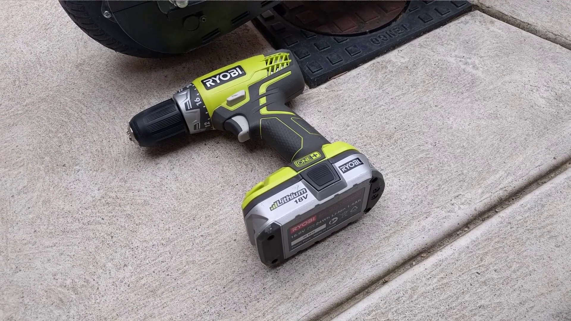
I needed to upgrade to lithium power but I wasn't keen to drop the cash until I had an better idea of what I could expect. Instead of buying new batteries and a speed controller, I decided to work with what I had. The stock speed controller and the two 18V 1.4Ah Ryobi lithium drill batteries I had already. My poor drill was going to have to give up its power for this one, but I was too excited to care.
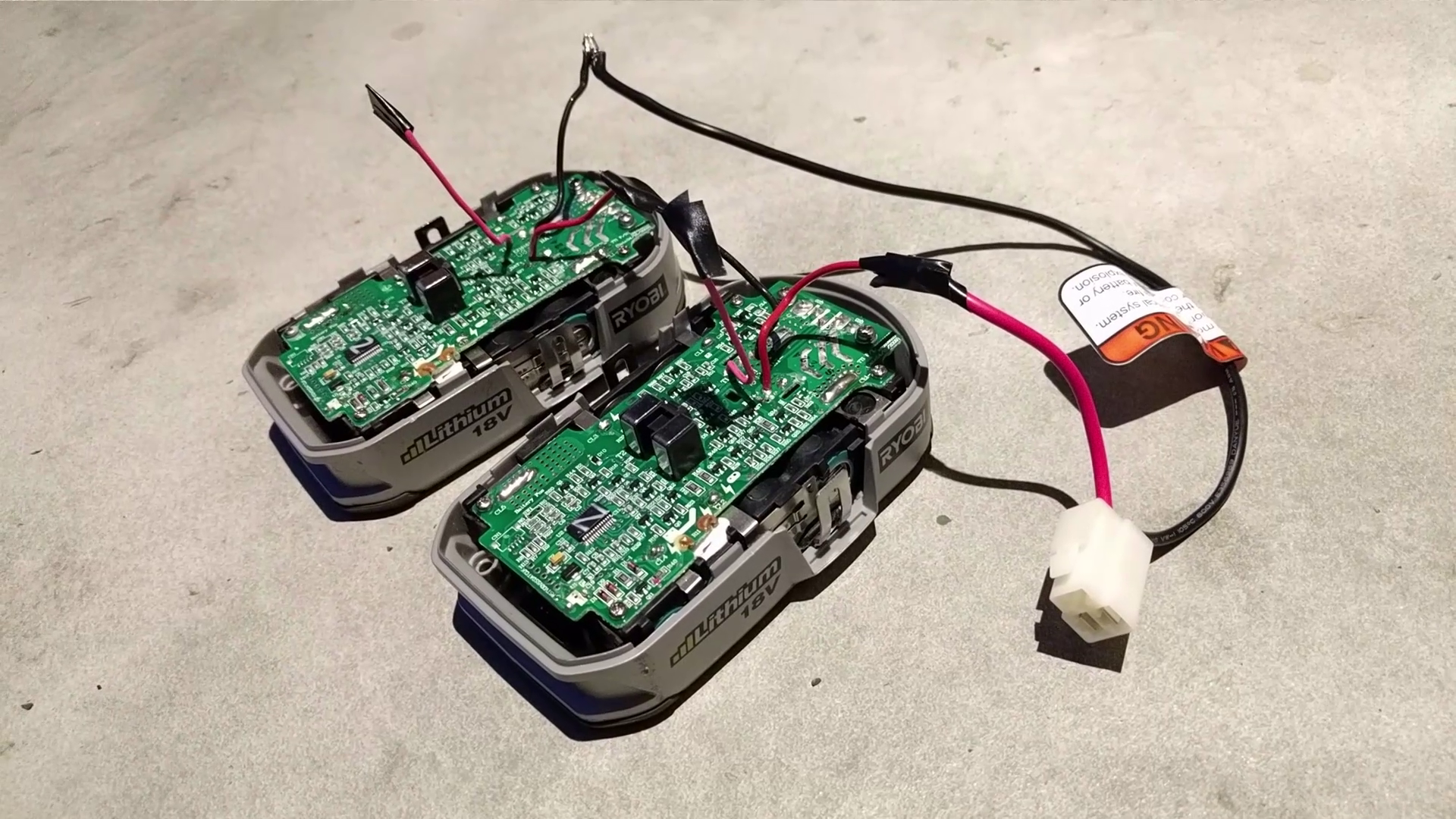
Using the connector from the stock batteries, I wired the Ryobi batteries in series to make a 36V pack. I plugged everything in but initially, nothing happened! A bit of a twitch but no drive. I could hear a relay clicking every time I hit the throttle though. I delved deeper.
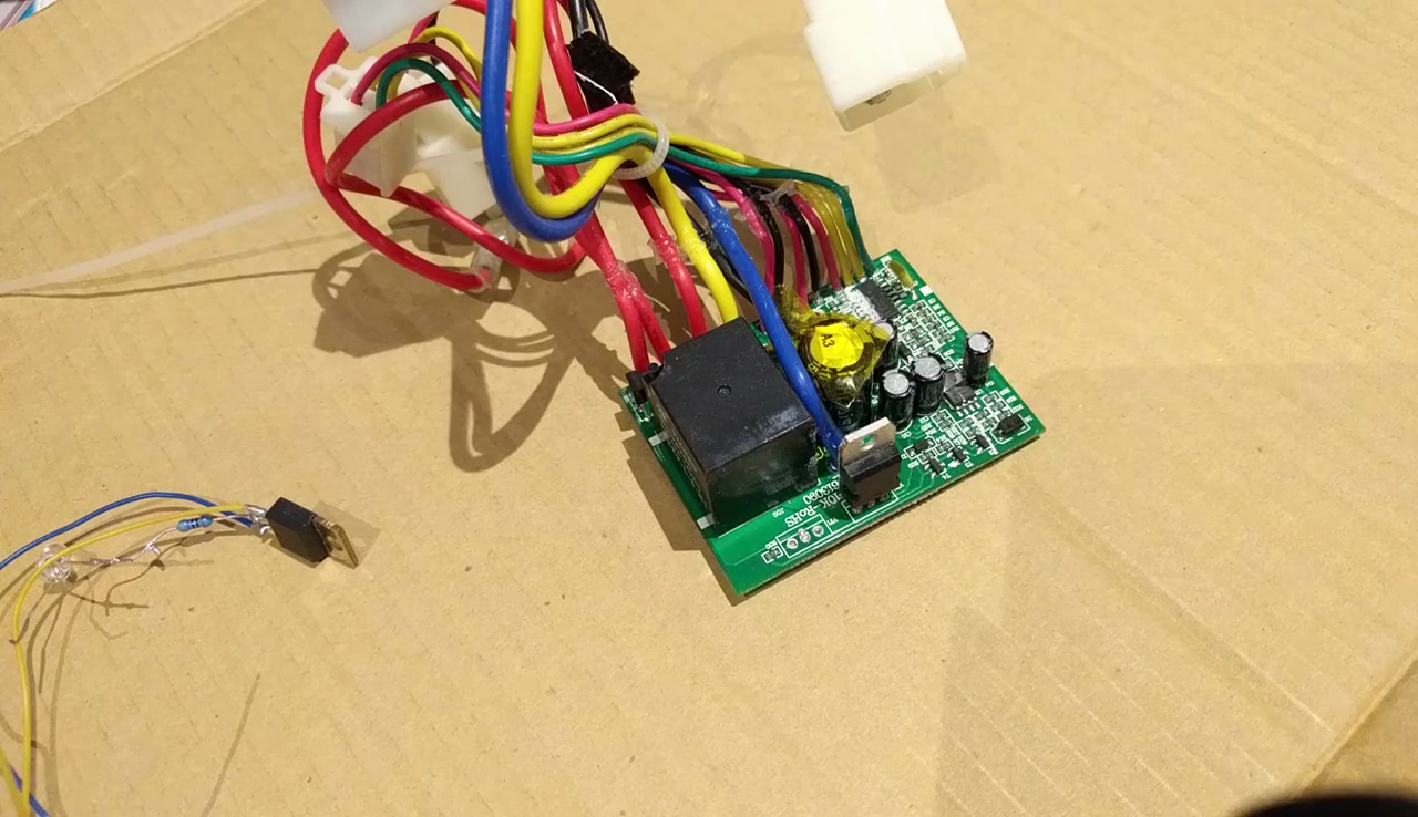
After tearing down the stock speed controller, I found the culprit. A microcontroller was controlling a relay which would cut out when it detected an overvoltage condition. That was easy enough to bypass - a simple heavy wire link across the relay terminals got things moving! But performance was still somewhat limited. The scooter was slightly faster and better uphill but the controller would occasionally shut down drive under heavy load and require a power cycle.
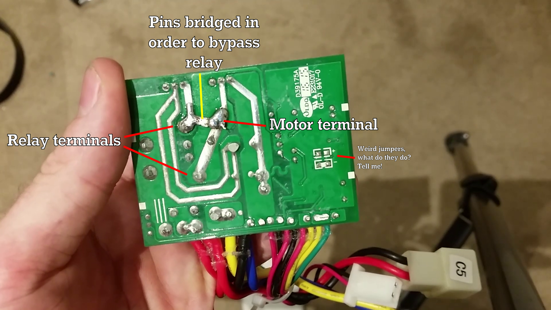
If you know what those weird jumpers do, PLEASE tell me! My curiosity is killing me. I should probably just trace where they go already.
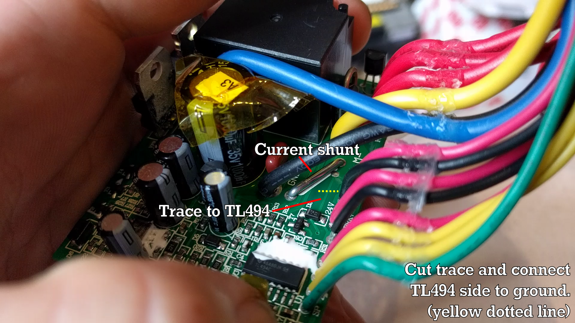
I was very lucky - the manufacturer hadn't ground the identification off any of the parts. There was some white goop but it came away easily enough. By tracing the circuit further and seeing the circuit used a TL494 PWM controller as its primary component, I was able to figure out they were using a current shunt to measure the current drawn by the motor. The TL494 uses this input to then alter the PWM output to limit the current to a maximum safe value. Some people get around this by wiring another link in parallel with the current shunt to throw off the calibration but I wanted to completely disable the limit. Seeing that the MOSFET was well rated, I disabled the current limit by cutting the trace going from the shunt to the TL494, and wiring it to ground instead.

Riding it like this is twice as dangerous, and twice as fun, too.

Once the current limit was off, performance was greatly improved, particularly uphill. Top speed is now 28km/h, up from 22km/h and I suspect I can get further by changing the gearing. I can't wait to install a proper set of hardcore LiPos and do more mods! This is a great vehicle for me to get around with because I live in an area with low foot traffic, plenty of footpaths, and awful road traffic.

Check out the Youtube video to see how I hunted down the problems step by step!

Portable Network Graphics (PNG) - 1.90 MB - 03/01/2016 at 10:17

Preview
Download

anatomy.png

The basic layout of the scooter's stock drivetrain.

Portable Network Graphics (PNG) - 1.35 MB - 03/01/2016 at 10:10

Preview
Download

vlcsnap-error872.png

My trusty Ryobi 18V cordless drill.

Portable Network Graphics (PNG) - 2.46 MB - 03/01/2016 at 10:07

Preview
Download

vlcsnap-error874.png

Me on the scooter. Mid-skid. I got it in slow-mo up on Youtube. ;D Skids are fun! #rearbrakes4lyf

Portable Network Graphics (PNG) - 1.58 MB - 03/01/2016 at 10:07

Preview
Download

currentlimitbypass.png

How I bypassed the current limit on the TL494.

Portable Network Graphics (PNG) - 2.21 MB - 03/01/2016 at 10:07

Preview
Download

View all 8 files

  • Fast Scooters, the Easy (eBay) Way

    TK01/11/2018 at 07:13 0 comments

    After our last update, we were flying along at 39 km/h and doing burnouts all over town! But all great things must come to an end, including the poor MOSFETs we'd crammed into that stock speed controller.

    This gave me a new opportunity - why not check out some of the off-the-shelf overvolt kits and see how they go with the ridiculous motor and battery setup? That's exactly what I did!


    Fundamentally, results were just okay. The overvolt controller from Fastscooters isn't built to handle such a large motor and we only hit 26 km/h. That said, it's an easy, accessible way to get into scooter mods, and that's cool. 

    Naturally, we're going to cram it full of fat MOSFETs and ruin the current limits. Watch this space. 

    Till next time,
    TK out

  • Gearing - The Key to Speed

    TK06/02/2017 at 03:43 0 comments

    After our last outing, we knew we had the power, but we lacked the raw speed. What to do? Gear it, obviously! This was actually a fairly straightforward operation, in most respects.

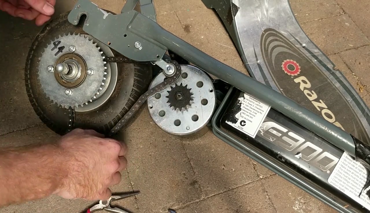
    Parts were a little hard to come by - eBay came up short on sprockets, and without machining capability, I had to find the right ones elsewhere. Thankfully Alibaba came up with the goods and saved the day. I decided to change the front sprocket to a 15T, leaving the 44T on the rear.

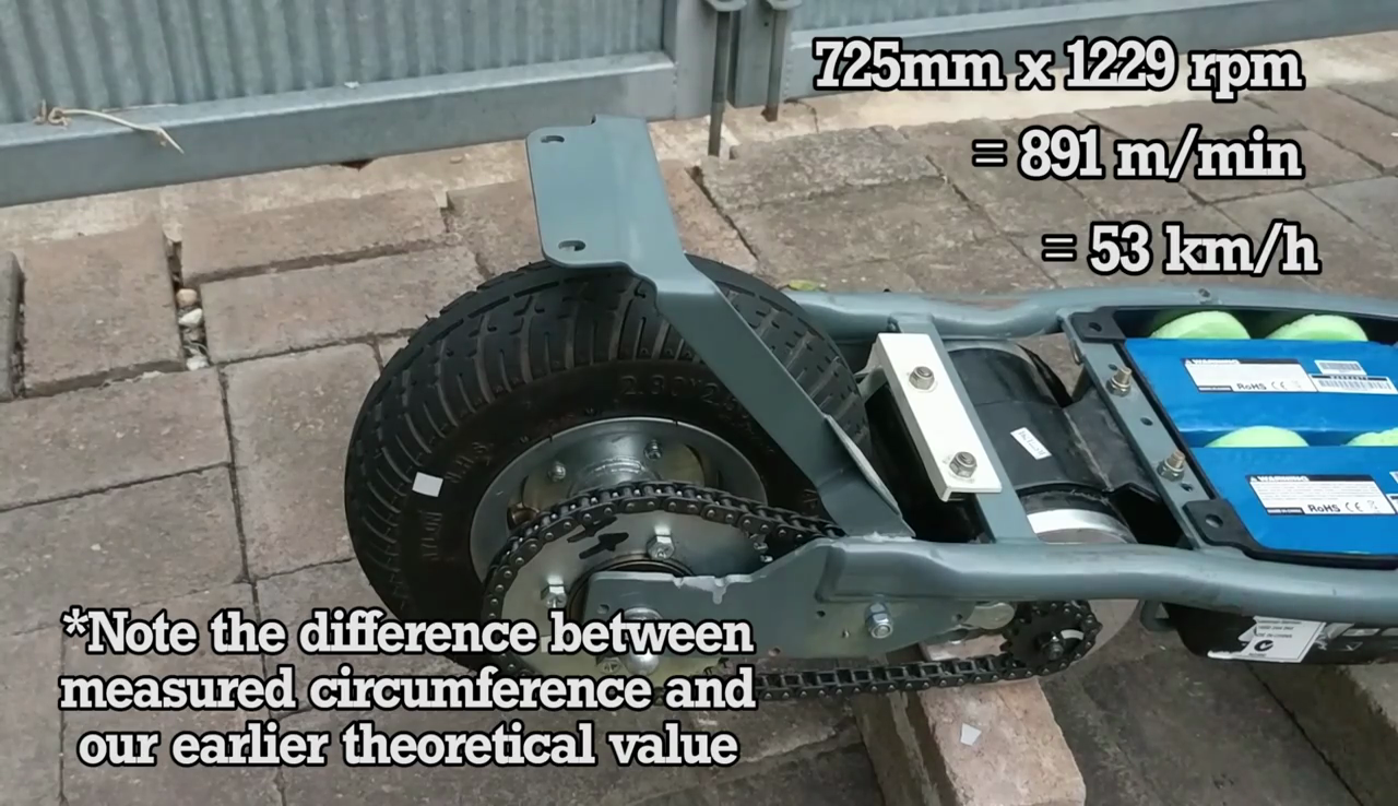
    I got things buckled in, admittedly with the chain stretched to its limit. The first runs were not quite up to scratch - only 34 km/h. An improvement, but not enough. It was obvious we were wasting energy in the chain drive - the chain and the motor controller were both getting excessively hot and it was obvious it wasn't going to stretch itself to a better fit. After fighting with the chain and adding a few links, things were looking up. I measured the scooter's rear wheel diameter, and then sat the scooter up on bricks and ran the motor.

    Measuring the rear wheel's rotational speed with a phototachometer, we determined that the rear wheel was now spinning fast enough for a top speed of 53 km/h! Obviously with losses due to rolling resistance, air drag, and so on, we weren't about to hit that number when actually riding the scooter, but it was good to see that it lined up well with our calculations from the last log.

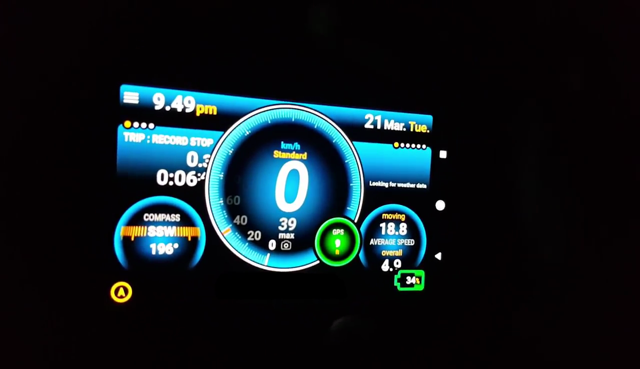
    I took the scooter out to a nice long straight, and reached a top speed of 39 km/h, and I can confirm that yes, this feels positively AWESOME. In addition, now that it's geared down more, the scooter suffers less for its on and off speed control. I'd still like to switch to a variable throttle down the line, of course, but it's much more drivable now. Oh, and if you were wondering, with a little WD40 to help? Yes - it'll do burnouts.

    I'm really digging the scooter now that it's properly quick, and I'm looking forward to flying around the neighbourhood carrying an entirely appropriate amount of speed. It's now got me excited for the next scooter build...

    Till next time,

    TK out.

  • Big motor for the Razor E300!

    TK02/15/2017 at 05:18 1 comment

    We still aren't going fast enough. It's time for MOAR MODS!

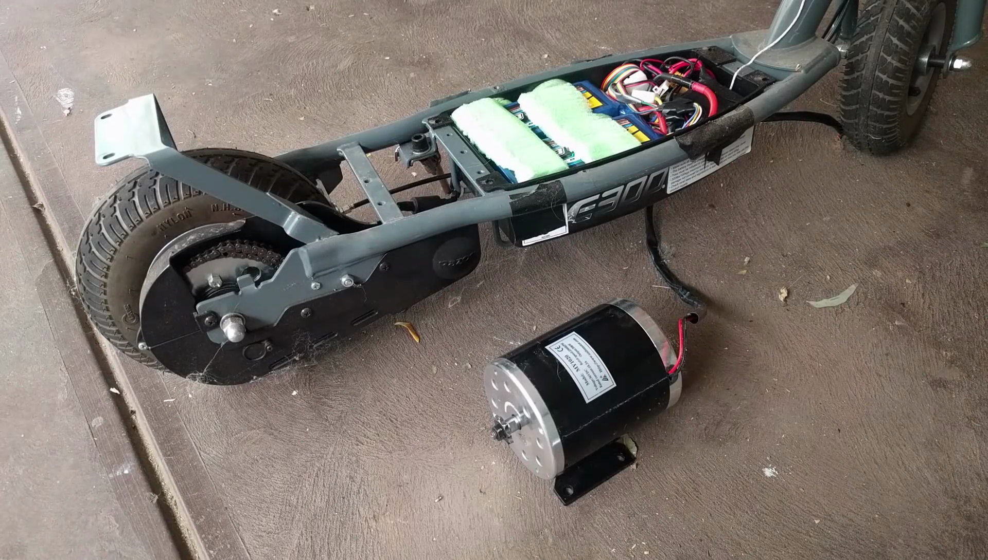
    Thus far, our meddling had blown us up a speed controller, which we duly repaired. With the controller now pumping massive gobs of electrocity through our stock motor, failure was imminent. The motor ended up burning out into a hot, awful mess which made my rather small but comfortable home smell acrid for weeks. I'm not even kidding. Weeks.

    The 36V badboy I enlisted for the build from eBay.

    We needed to upgrade. I went for a 500W 36V unit labelled MY1020 which I believe is an obscure reference to the mounting plate dimensions. If you know more on that, let me know. There were issues from the get go - it simply didn't fit.

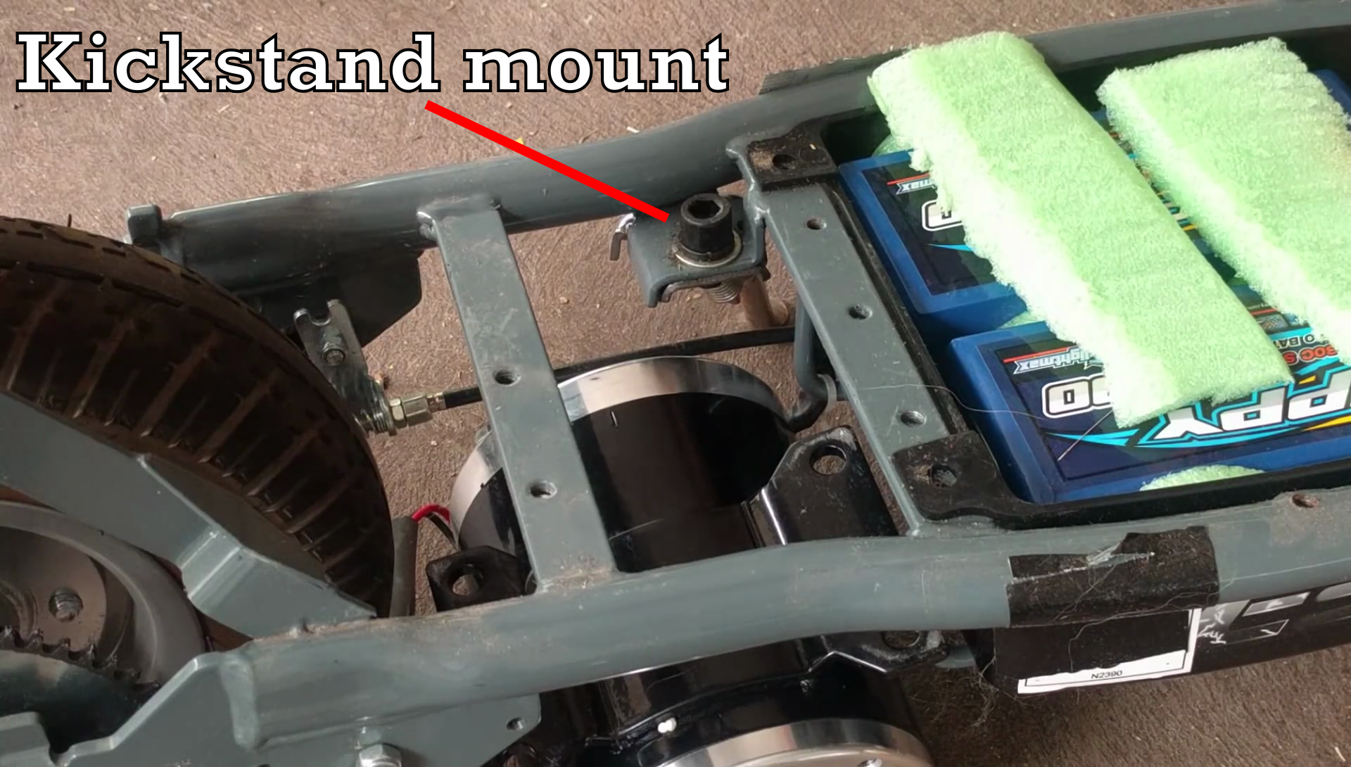
    First to go was the kickstand - the mount was in the way of where FAT PRECIOUS MOTOR needed to be. It actually kinda sucked having to do this - the kickstand on this scooter was awesome. Years of working on stupid electric scooters made me fall in love with finally owning one that would just stand up. That said, I was tired of setting off with it down and then nearly stacking it when it impacted the ground at speed...
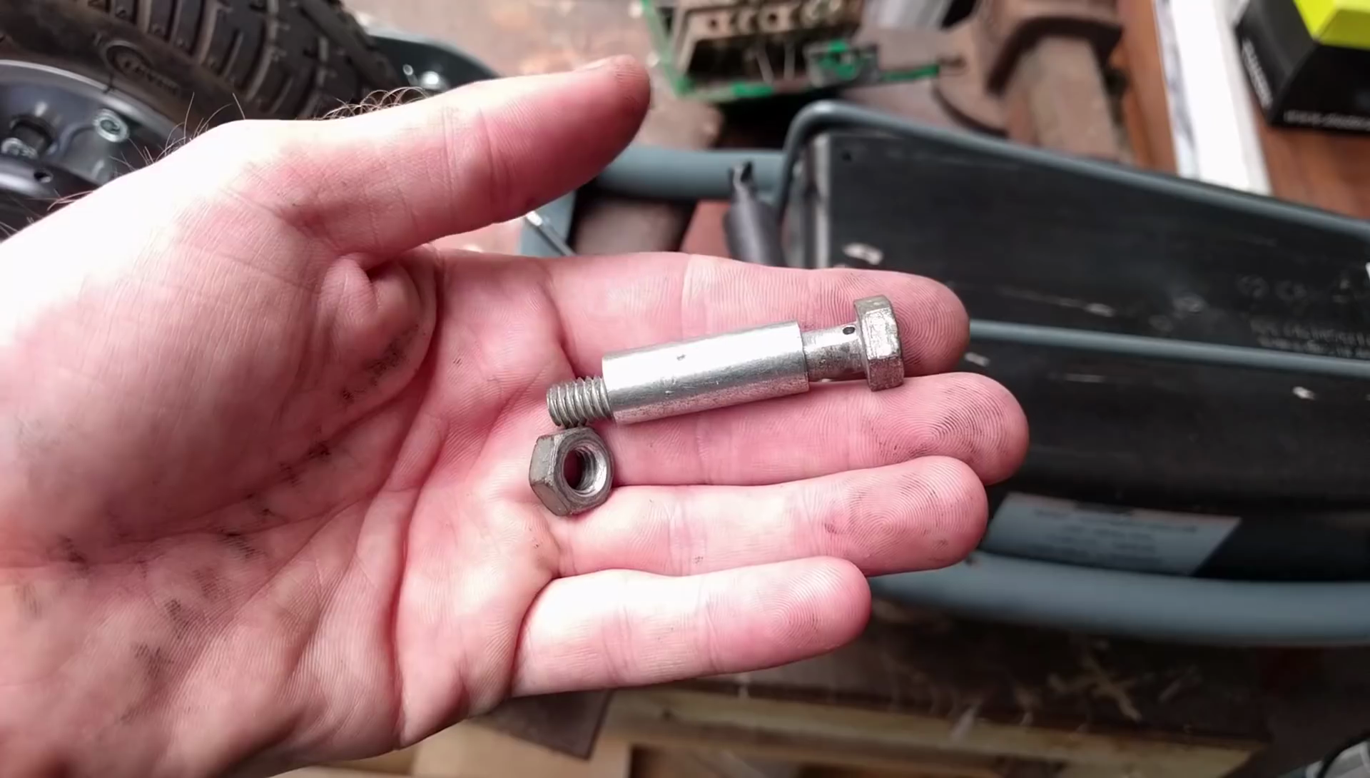
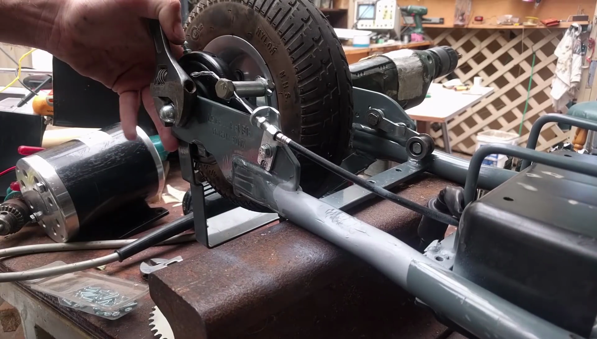
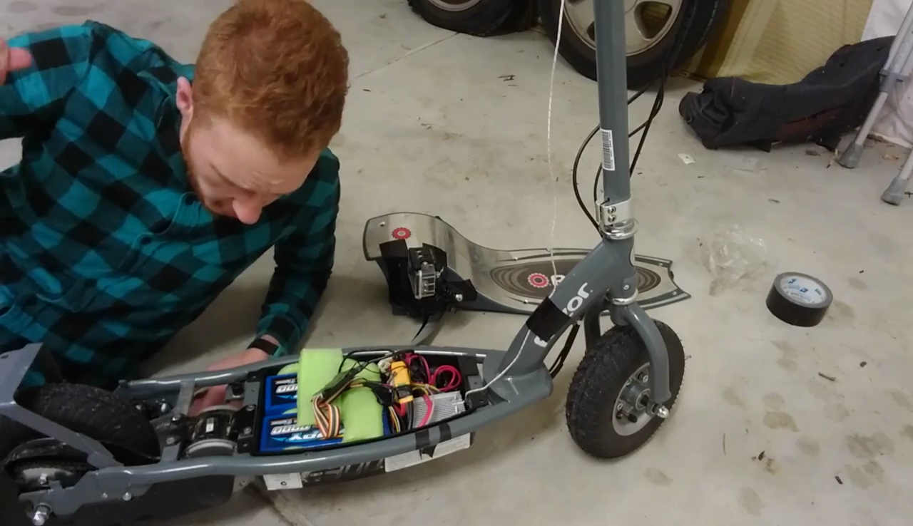
    Next up was the brakes. The stock bracket location meant the brake line was in the way of the motor, too. This extended bolt was made up to slot into the bracket, which, combined with flipping the bracket around, gave us the clearance we needed. Incidentally, we'd needed to shorten the sliding tube a little. The cordless-drill-come-lathe was the way to do it.
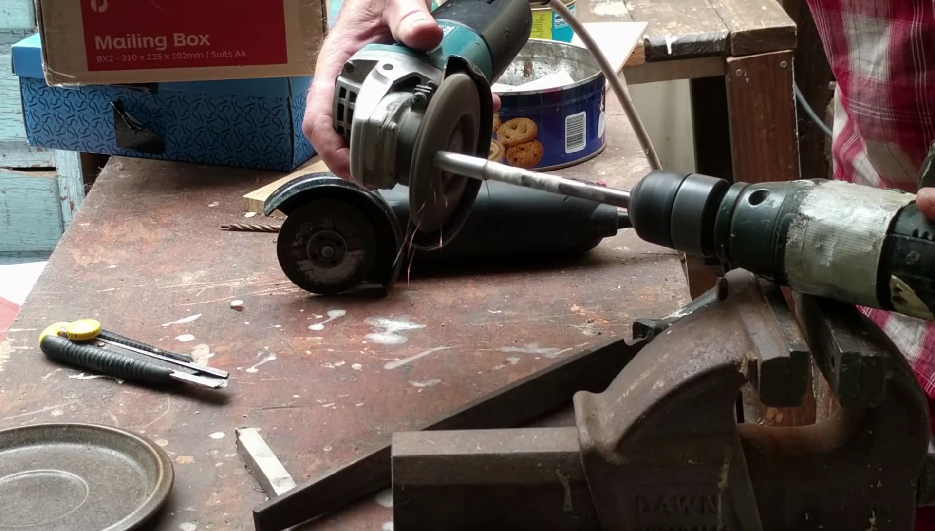
    Pictured: Cordless drill in lathe's clothing
    Simply chuck the workpiece into the drill and spin away. Then have at it with whatever the most relevant tool seems to be. We used a flap disc on an angle grinder. You can do all sorts of dangerous imprecise machining this way!

    The assembled brake assembly. This reroutes the brake cable nicely.

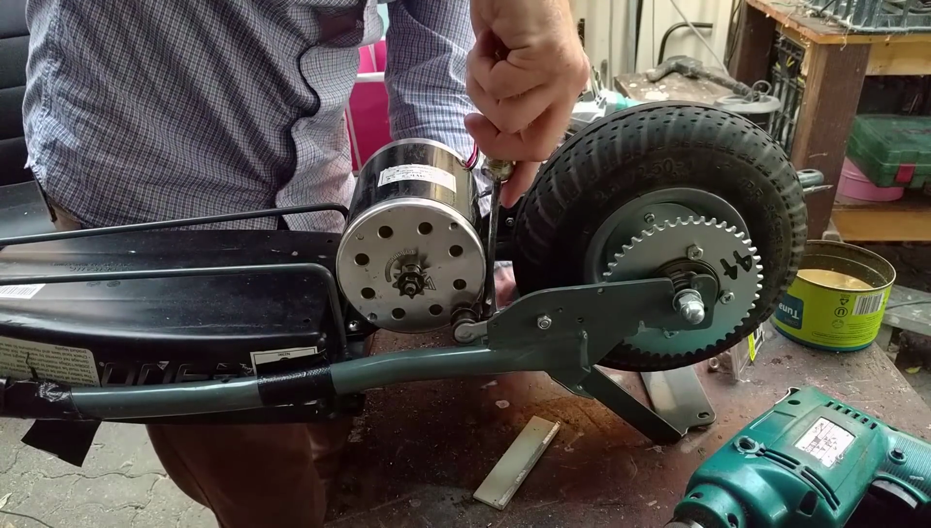
    With everything out of the way, it was time to drill some mounting holes for the new motor. Straightforward enough on one side, but on the other, we had to fab up a special bracket to clamp the motor onto the mounting rail, as the rail itself wasn't wide enough to meet up with the motor's mounting faces. An unconventional solution but it should do the trick until I can weld something up later.Bolting up the motor to the frame. Clamping bracket not easily visible. Note the 44-tooth T8F sprocket fitted to the rear wheel.
    With the motor in, it was then a matter of fitting the new T8F sprocket to the rear wheel. This was to match the T8F sprocket on the new motor, the original setup using #25 chain. Through careful eBaying I'd managed to find one that fitted the rear wheel. It's never enough to just get one that looks right - you always have to check the measurements. Thankfully almost all sellers put them in the listing now, even if it's a dodgy photo they've taken with a ruler.

    The original gearing was 11T on the motor, with a 55T rear sprocket. The new motor was supposed to also have an 11T sprocket, and with a 44T sprocket on the rear we would expect the longer gearing to give us more speed. But I'd ignored something that should have been blatantly obvious. That, and the motor actually shipped with a 9T sprocket. This sort of thing is par for the course on eBay.

    Calculating the ratios is disappointing:

    Original: 55T rear, 11T front: 5:1 gear ratio

    New: 44T rear, 9T front: 4.9:1 gear ratio

    That's hardly any change at all! Oh well.

    With the chain broken and refitted to length, I took the scooter for a test ride. After just 50 meters the chain came off! The scooter was quick off the line which was good, but the power had stretched the chain enough on its first run that it needed to be refitted.

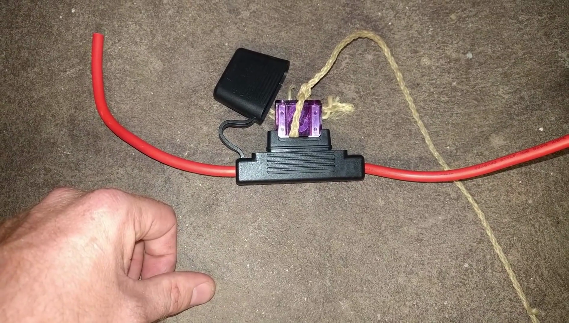
    After refitting the chain, I realised I wanted an emergency cutoff in case the MOSFETs failed again. I decided to press a 100A megafuse & fuse holder into service. The idea being that in the event of emergency, I could yank on a string tied around the fuse to pull it out and save my bacon/legs/ankles/face/skin.
    The fuseholder with fuse & YISHF (yank-if-shit-hits-fan) string....
    Read more »

  • Speed Controller Hax - Place your FETs!

    TK09/19/2016 at 05:00 2 comments

    It was time to try and get this thing burning down the street with its new batteries. We got to burning, at least. We definitely got to burning. Check out the video for the full story. Details below.

    Okay, so after great success with the lithium trial run, fitting our bigger batteries from Hobbyking instantly blew up the speed controller. When we dosed it with some hot, fresh amps, the FET was killed instantly. Most disappointing! Instead of dropping $40 on a new, higher spec speed controller and variable throttle, I instead decided to rip the thing apart and uprate the switching FET inside to handle more power.

    The speed controller, right, with the old blown IRFB3607, left.


    However, I had a problem - the IRFB3607 inside was rated to handle 80A & 75V. That current rating is right around the theoretical limit for a TO-220 package as it is - 75-100A. Replacing it with another TO-220 wasn't going to cut it. Instead, I had to get creative - I decided I'd go with parallel FETs to handle the strain.

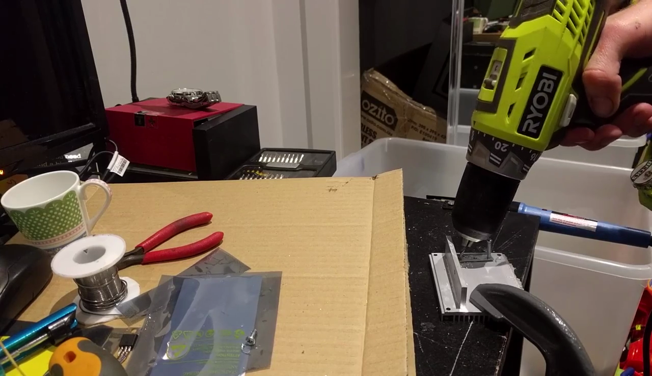
    Modifying the heatsink and mounting hardware for parallel FET GOODNESS.

    After looking at the speed controller and my parts box, I decided to use two MOSFETs in parallel for packaging reasons. I chose the TK100E08N1, rated at 214A & 80V. This is an example of the manufacturer rating the gate current capability of the silicon, ignoring the fact the device package can't effectively handle in excess of 100A.

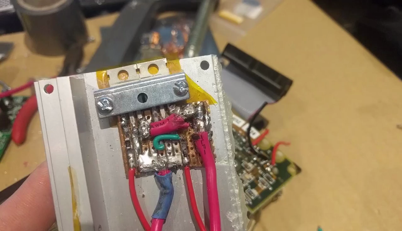
    I used a small piece of veroboard and modified the existing mounting hardware to fit the parallel FETs to the original heatsink. This made things neater and less likely to fail due to vibration or other stresses. Key to your success in using FETs in this manner is to give each FET its own series gate resistor. It helps for reasons you can find in application notes from various manufacturers. Oscillation is the biggest problem. I used a couple of SMD 10 ohm resistors I scavenged from an old hard drive.

    The parallel FET assembly. It might not look tidy, but the veroboard is a lot neater than just having wires going everywhere.

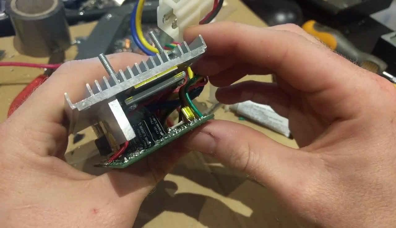
    After building the parallel FET setup on the back of the heatsink, I attacked the PCB. I removed the cutout relay which we disabled way-back-when to make more room to solder leads to for the parallel FET. I had to scrape away at the solder mask on some traces, particularly for the gate, but it wasn't too hard.

    Reassembling the speed controller. The new FETs are a good fit and make excellent contact with the heatsink.
    After reassembling everything into the scooter, it was time to test. AND IT WORKED.

    IT WERKS!

    SORT OF. The scooter was initially incredibly quick, but quickly lost power. I couldn't get close to the previous speeds I'd reached and there was a hot, burning smell. It was the motor.

    Me, glaring at the motor that just burnt me in dismay.


    At this point, I cannot warn you enough. DO NOT. UNDER ANY CIRCUMSTANCES. TAKE A BURNT OUT MOTOR INSIDE YOUR HOUSE TO WORK ON. My lab space and kitchen STILL smell like fiery death a WHOLE WEEK LATER. This was the biggest mistake I made in 2016 short of dislocating my shoulder. I am not even kidding.

    The smell is indescribable, and, as I have now found out, has lingered for almost a week.
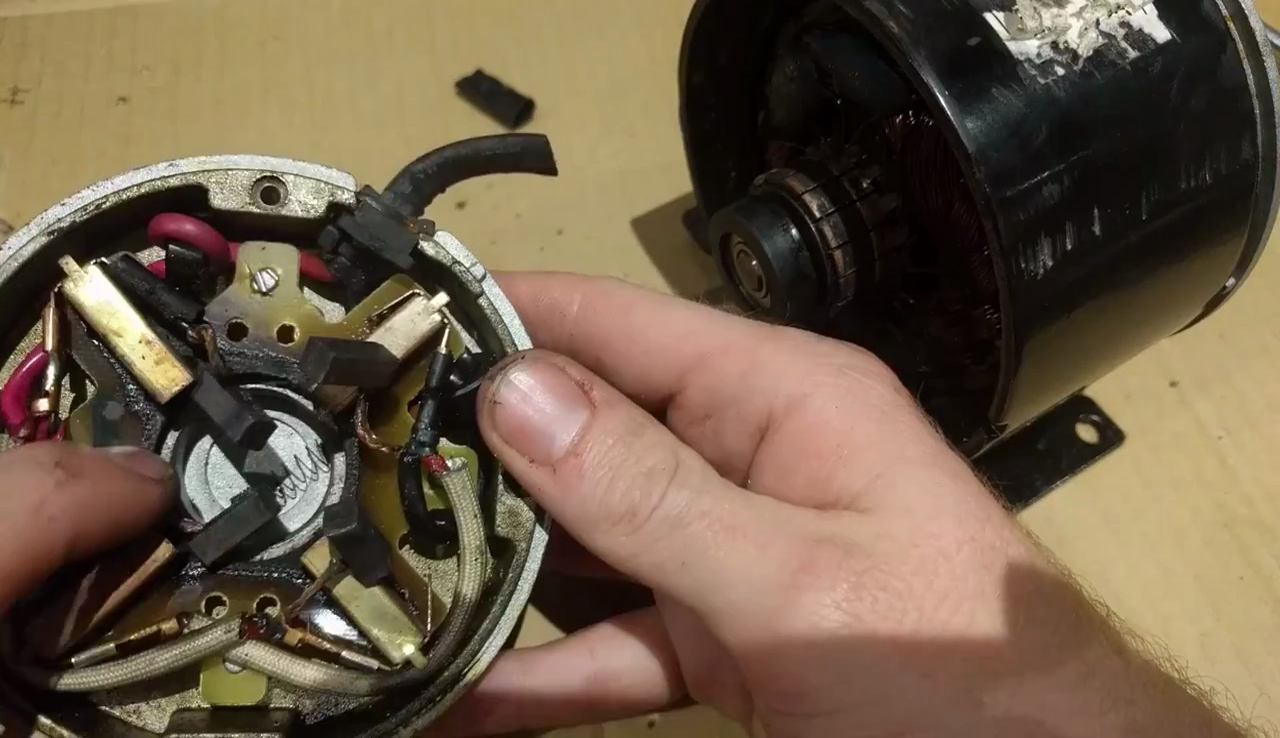

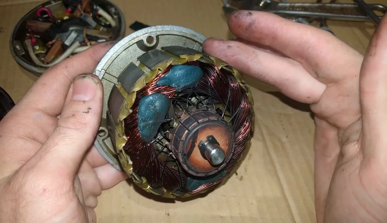
    The failure mode is thus: the motor overheats when pushed beyond its rated voltage & current, causing the insulation on the coils to melt and break down. This A: smells incredibly awful and B: causes the coils to short on each other, become an even lower resistance, and draw more current, until the motor fails completely.

    Burnt. Awful. Sad.


    Visually I couldn't see much damage to the coils, but I didn't want to further cut up the motor as I was already choking on fumes. After 40 minutes out of the scooter the rotor was still hot to the touch. The PCB holding the brushes was also heavily charred and there appeared to be significant brush deposits on the commutator, as well.

    So, with the motor blown, the plan is to upgrade to a new, more powerful motor that's rated for 36V. This leaves me in an uncomfortable...

    Read more »

  • The Big Battery Swap

    TK08/16/2016 at 04:18 2 comments

    After the remarkably successful test with the Ryobi drill batteries, I was ready to upgrade to a proper lithium pack. I specced a couple of 5 cell, 8 Ah badboys from Hobbyking, with which I'd build a 10S pack. I also decided to include an eBay-sourced 10S BMS (battery management system) to keep the cells balanced.

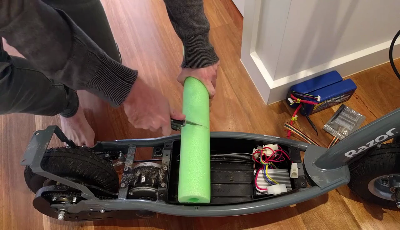
    I decided I'd use a pool noodle as a source of cheap foam to mount the batteries safely and snuggly in the scooter frame. This worked great and it's hard to lose for $3.

    Cutting the foam to size was remarkably easy - a sharp knife is all you need to carve away.
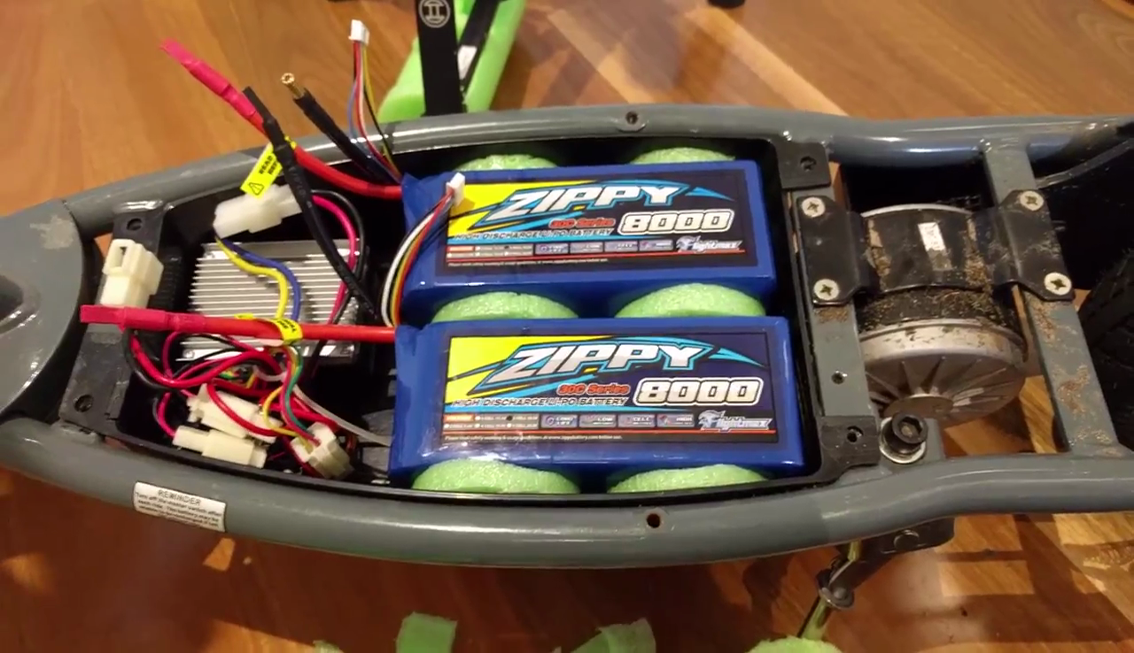
    I was stoked with how neat this turned out. The batteries are held in place really well - highly recommended! Next up it was time to do the wiring for the BMS.
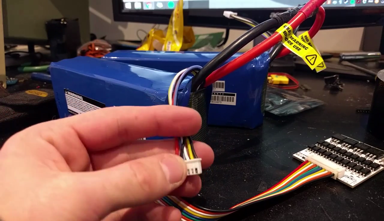
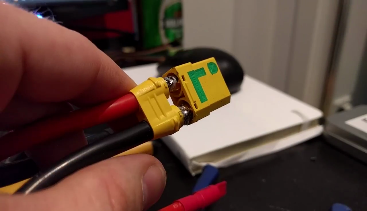
    It's a simple enough matter of soldering up the 10 individual cells and then the main battery discharge wires. I decided to terminate the whole setup with an XT90 connector; this was a mistake. Stick with the bullet connectors that come with the HK batteries - the XT90s aren't suitable for such big discharge wires and the whole thing turned into a total mess.

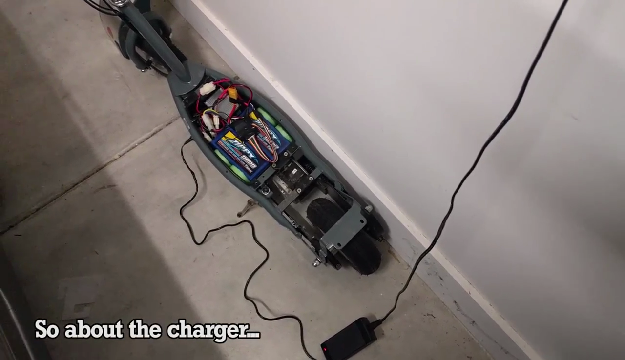
    I also had to spec a 42V lithium battery charger from eBay; this one is sold for charging ebikes. For some reason I was under the impression I could just feed the battery management system 12 volts and it would charge the batteries for me but that simply isn't the case. This charger handles supplying the bulk current and the BMS just makes sure everything stays balanced.

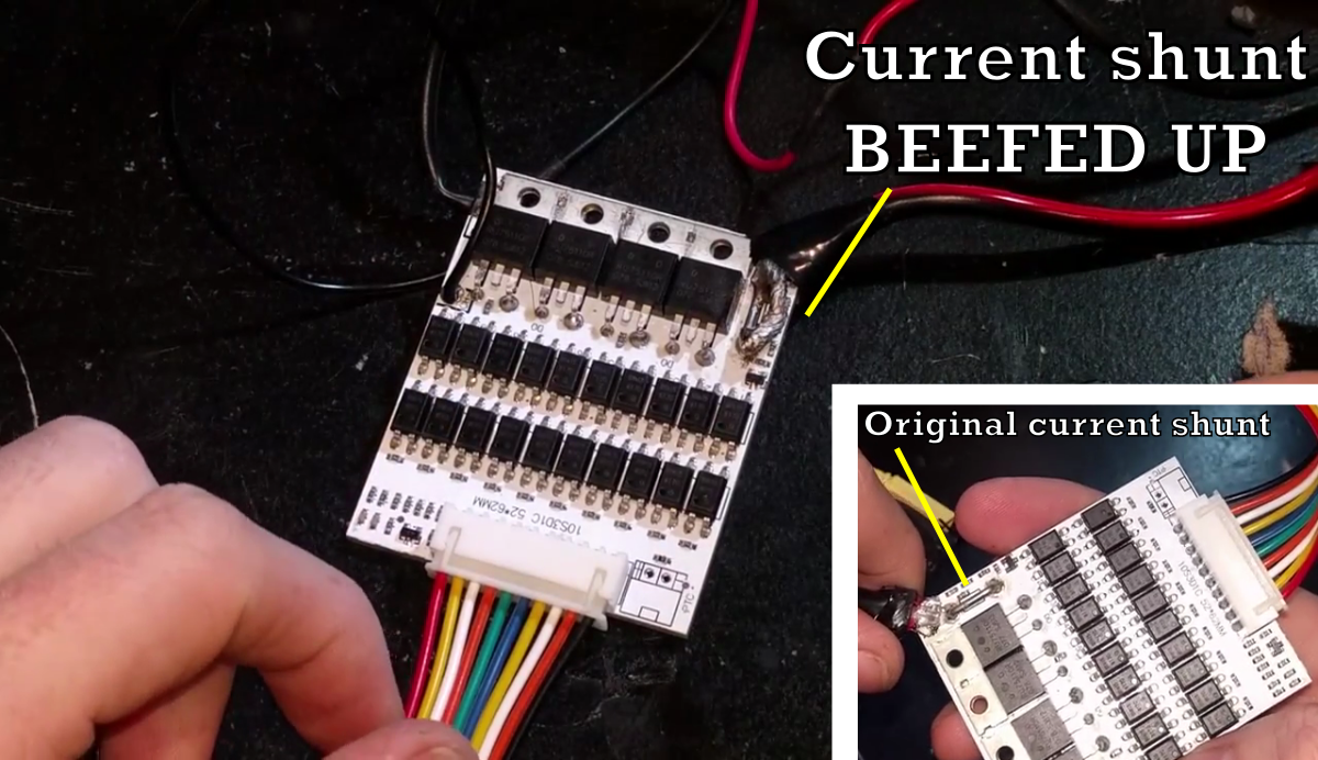
    With everything wired up, I went for a test run. I jumped on the scooter and pulled the throttle but nothing happened! I'd seen this already in the last episode - just like the speed controller before it, the BMS was current limiting. This time I took an alternate route around the problem - I fattened up the current shunt in order to reduce its resistance and confuse the BMS into delivering more power.

    This works because the circuit measures the voltage drop across a known resistance (the current shunt) to determine the current flow. Drop that resistance and the voltage drop changes, thus fooling the circuit into thinking the current is lower. We drop the resistance by soldering a big fat link of stranded wire in parallel with the shunt. So, how'd it go?

    ...

    ...not well! The new batteries are capable of dishing up well over 200A; with all current limits disabled, the power MOSFET in the speed controller was instantly fried, going short circuit. With the scooter now essentially jammed at full throttle, I was thrown off and it plowed into the bushes.

    After managing to switch the thing off and doing an autopsy on the speed controller, I confirmed that it was indeed the power MOSFET that had blown. A shame but not entirely unexpected, I suppose. So what to do next? Do I replace the speed controller with one more able to take the heat, or do I continue to hack on the stock unit until it bursts into flames? Keep an eye out... this isn't over yet!

    TK OUT.


View all 5 project logs

Enjoy this project?

Share

Discussions

Jason wrote 10/27/2018 at 16:23 point

hey man. Can I chat with you about a separate project???

It’s similar but it has a Bluetooth circuit board for the on off switch. And it has the eprime hub motor. And the eco smart battery. It’s crazy. I need to bypass so much though. I need help!

  Are you sure? yes | no

Alex P wrote 07/31/2017 at 14:02 point

Hi, i found an E300 very cheap. Buy its heavy to carry..,need to carry.

Can I convert it into a simple kick scooter If parts are removed? How much will it weight then?

Thanks

  Are you sure? yes | no

Jbarlow1007 wrote 01/29/2017 at 21:47 point

think your scooter mod's are cool . Big fan of the razor E200/300. Csn u tell me is the frame to the e300 bigger then the E200. Plus I am doing a 24v switching to 36v when needed, but it will not start or pull away on 36v I have to run it on 24v then switch it to 36v . If I do that Wire trick acrossing the back of the boared . Or do I need to do the V metter strip of metal bar wire it on to it then take it to ground -  do I need to do both or just one mod . Please help 

  Are you sure? yes | no

Jbarlow1007 wrote 01/28/2017 at 23:24 point

wow you did your scooter so well , and can I say it was a cool watching you. Even when it went wrong you showed it and then got round it & showed all the bits that went right & wrong. Like me I love wiring and putting thing together.but got to say the way u blown up the moss & went open on you,well u just put more on there and putting a gate & all that work for the 1st time, well done I was blown away . Dam u r good I could not of done that. Quick Q I need to by pass my E200/300 controller I put 36v and it clicks . I see what u did . Now I no the 1st bit u did to it did that work . Or do I just do the other bit jump wire to ground . & it thst the black ground or the yellow ground . I am only going to 36v but with two motors . But I tryed to put a wire across the back of the board like some say to do . Making that bit of metal thicker but put 36v to it and it clicks . Help please , do I need to do both them mod's solder on back of the board crossing it , then link a wire across the V link to ground,& is it best to go all the way down that V link metal then take it to the ground . Sorry to ask to much . But I need help on this . Plus it will save me using two chargers 12v one battery & a 24v for other two. Please help if u can . 

Love your work and keep up the vids . 

& if u put a 12 or 13 sprocket on front and go for a 44 back it will fly . Big fan of your work 

  Are you sure? yes | no

peterweiss wrote 09/27/2016 at 03:23 point

Longtime user of e300 with 2 speeds. 1st speed is (2) 18v Ryobi in parallel. 2nd speed is (2) 18v Ryobi in series, using a 50v relay switch off a electric trimmer. I am on my 3rd motor, which I buy on eBay for 30 bucks. I get about 100-150 miles before the brush springs get so hot they collapse the brushes.

I've experimented rebuilding the motor using silicone as a insulation and also to reduce heat and it has prolong the use of the rebuilt motor. 

Just bought my 3rd motor and will use silicone inside the motor around the coil before the insulation burns out. Will keep you kids updated.

Btw, i would like to see TK take e-shopping cart from Walmart, Costco or Safeway and mod the f$&k out of it... 

  Are you sure? yes | no

TK wrote 10/06/2016 at 21:52 point

Interesting hacks you're doing there! Thought about drilling cooling holes in the motor? Could be dodgy though, you don't want to put a drill bit through your coils.

Hahah, it'd be fun to muck around with one of those carts. Never seen one out here in Australia.


  Are you sure? yes | no

peterweiss wrote 10/09/2016 at 18:49 point

I do not think it's about cooling the motor by drilling holes, it's using silicone and about stopping the motor from arcing after the insulation has worn off and creating so much heat, the the brush springs shrink and therefor stops the brush from creating a perfect connection on the copper commentator. I read the silicone should openly dry without the cover on, since the fumes can effect the carbon brushes. 

  Are you sure? yes | no

Nathaniel wrote 09/09/2016 at 12:13 point

Dude, well done, love the project.

  Are you sure? yes | no

TK wrote 09/09/2016 at 12:44 point

Thanks dude! more to come ;D

  Are you sure? yes | no

nioko wrote 03/07/2016 at 06:46 point

Hi, I bought one of these used for cheap to do a Lithium mod as well. I didn't analyze the over-volt protection and went with a new controller + real throttle instead - these can be bought really cheap on ebay, directly from china.

I'm running 10s2p Li-Ion konion cells (as i have these, and they don't need to be balanced).

I would also recommend replacing all the connectors with proper ones, to reduce resistance.

Ride safe.

  Are you sure? yes | no

Stephen wrote 03/06/2016 at 08:12 point

Love the project. I have an E200 moded for 7s 25c 5Ah LiPo power.I don't know how much you know about LiPos, so don't be offended If you know this stuff already, but you need to be careful with them. A balance/charger is a must, or at least a cell balance meter. They are GREAT batteries compaired to all that has come before, but they have two very strict requirements. They can't be over charged, and they can't be under discharged. Protect your investment with a good charger. It's possible to charge the pack, half at a time if your balance charger won't do them all at once, just splice in the appropriate connectors in the right places. The Zippy Compact 7s comes with two balancing plugs. one for 3 and one for 4 cells. I spliced into those and just didn't charge over 2~3 amps. It was still quicker than the LeadAcid was, just more work. Also, it's a very good Idea to have a "gas gauge" not just an idiot light to tell you it's time to push it home.

I hope that some of this was helpful. Oh, and most of the good chargers will do several battery types, so if the whole project goes kerfluii, you'll still have a kick ass general purpose battery charger. Cheers!

  Are you sure? yes | no

Jack Laidlaw wrote 03/05/2016 at 00:58 point

Love your project just watched the video and thought it was great!! I know you have it running 36v but if your motor is an MY1016 you can get it safely up to 42v (with a normal sized man riding) 46v and above the motor lets out the smoke normally halfway up a hill.

  Are you sure? yes | no

TK wrote 03/05/2016 at 01:51 point

Thanks dude! Interesting, I will see if the motor has any identifying markings...

  Are you sure? yes | no

TK wrote 03/02/2016 at 21:20 point

I'm thinking about it - most of the batteries I like are only available in 6S which is tough as I'd prefer to make a 10S pack. If I'm going to that level, I'm worried this thing will fail.

  Are you sure? yes | no

Michael Vowles wrote 03/02/2016 at 21:05 point

Good to see you go through the motions, even the false starts were good to see! Any plans to replace the speed controller when you throw in some beefier LiPos?

  Are you sure? yes | no

Similar Projects

Does this project spark your interest?

Become a member to follow this project and never miss any updates