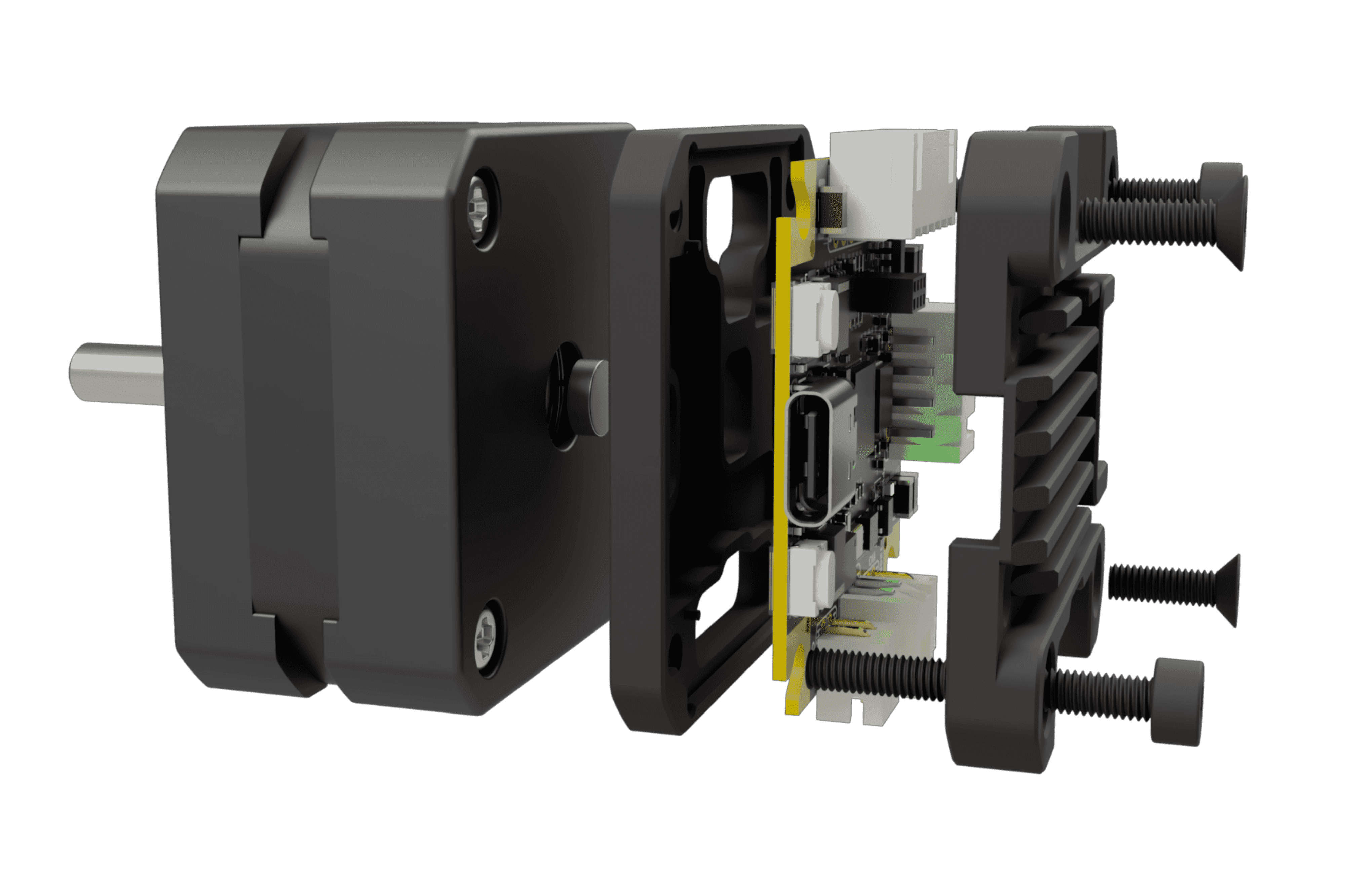
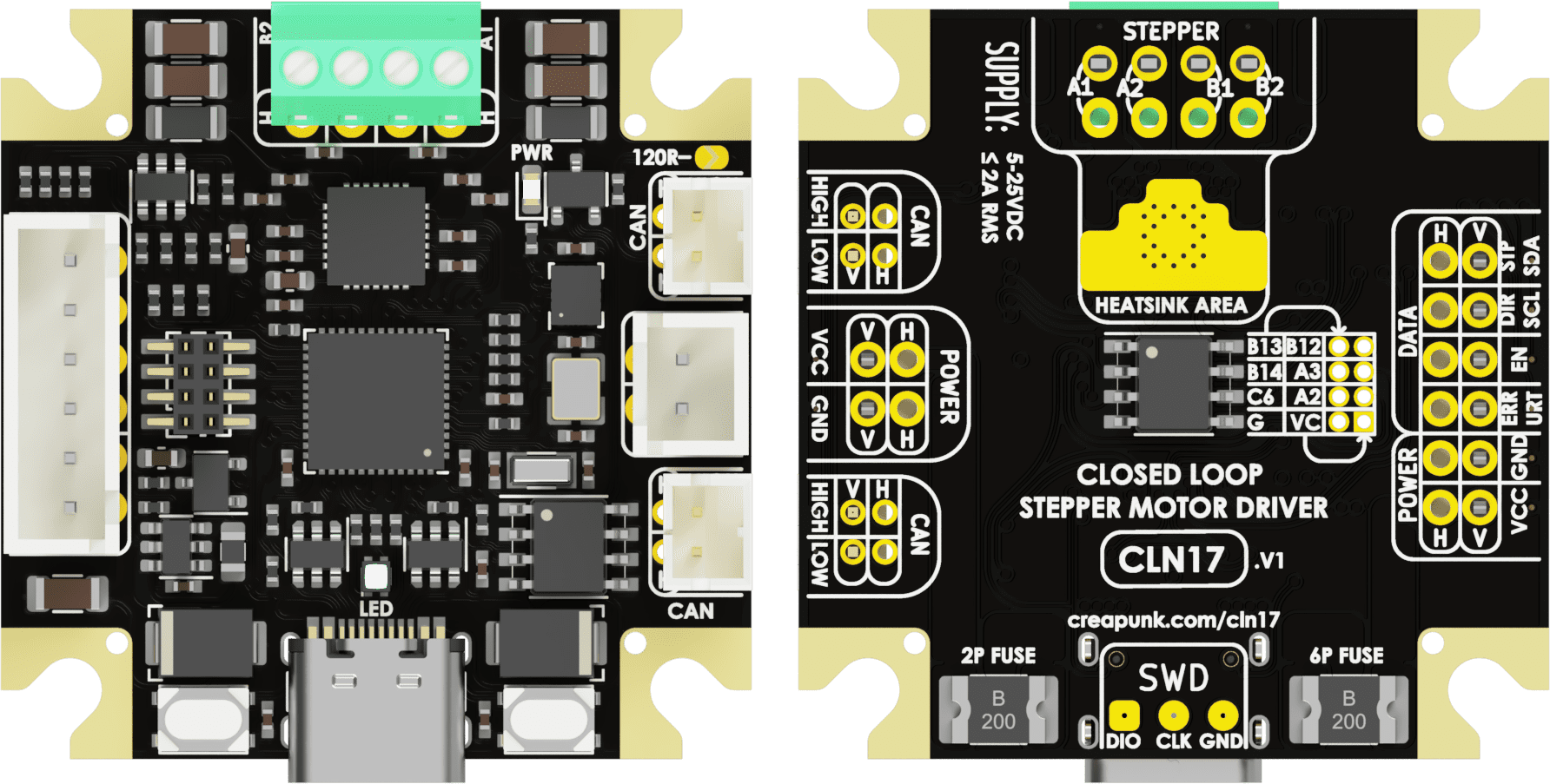
Board Diagram
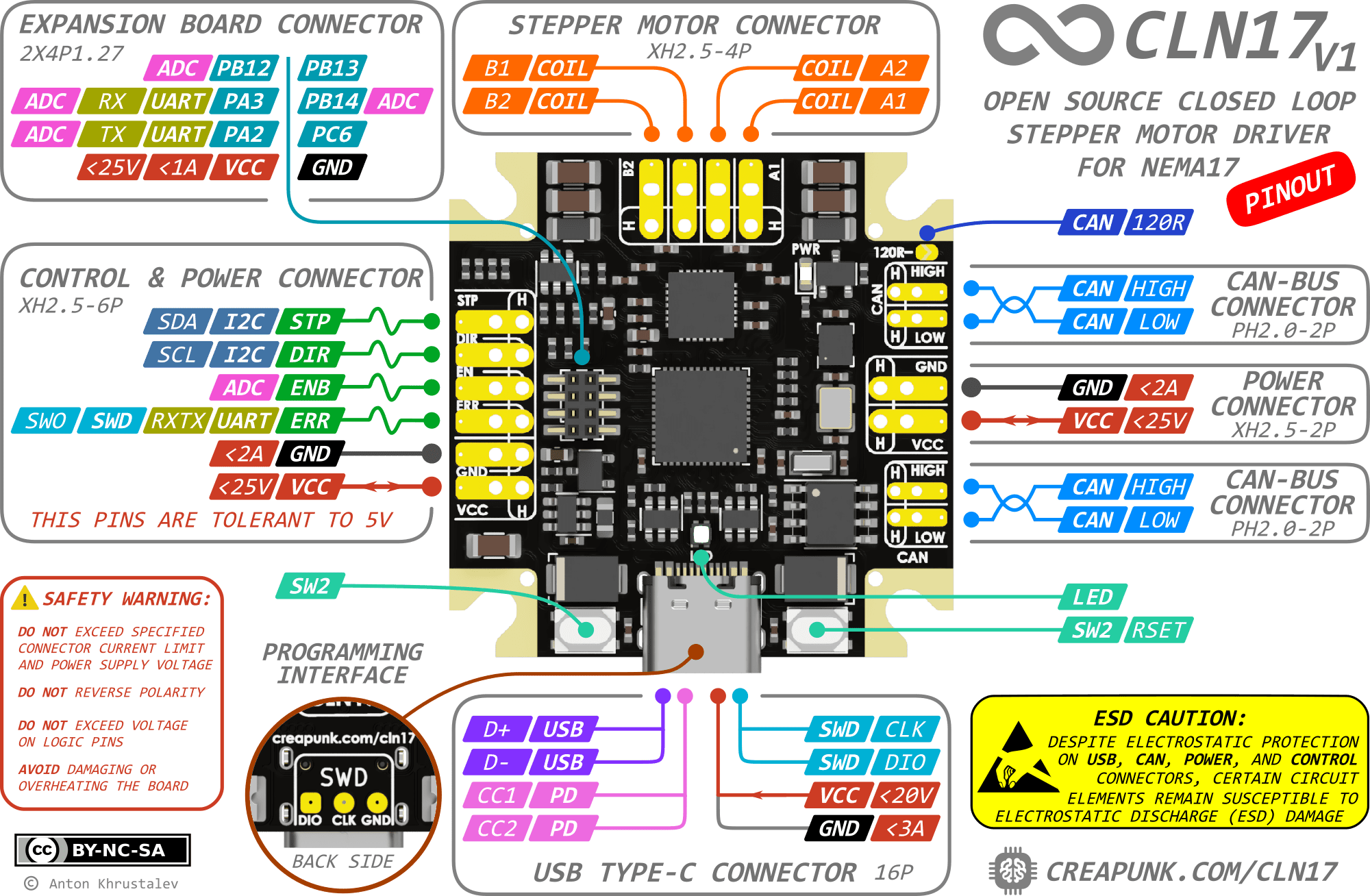
Key Features | All Features
- 🕹️ Closed-Loop Control: Enables precise motion in challenging conditions.
- 💪 Adaptive Torque Control: Optimizes energy efficiency, reduces stress, and extends motor lifespan.
- 🧩 Reliable Operation and Enhanced Safety: Ensures reliable operation and protects users from potential harm.
- 🛡️ Modular Concept: Provides flexibility and cost-effectiveness through various configurations and expansion boards.
Key Specs | All Specs
- 🔌 Wide Input Voltage Range: 5-25VDC with reverse polarity and surge protection
- ⚡️ Powerful Motor Control: 1.4A RMS current per phase with up to 2.5A peak and up to 1/256 microstepping
- 🚀 High-Performance MCU: STM32G431CB Arm Cortex-M4 running at 170MHz with Classic EN/DIR/STEP interface, CAN-Bus, I2C, UART and USB Type-C with PD2.0 support,
- 🔒 Compact and Durable Design: 38x38mm PCB, with optional aluminum housing for heat dissipation and mechanical protection and minimal height of 7.5mm (10mm with connectors)
Applications | In-depth
- 🎓 Learning Platforms
- 🛠️ CNC Machines & 3D printers
- 🤖 Robotics & Automation Systems
- 🤝 Collaborative Robots
- 🔭 Camera & Telescope Stabilization Systems
- 🔬 Laboratory Equipment
- 🏭 Industrial Motion Control Systems
- 📳 Haptics & Force Feedback Systems
What is the project's status?
There are numerous updates planned for the documentation, including the publication of articles on related topics. Alsowill be provided insights into development process, announce new versions, introduce new features, and much more. Here's a concise breakdown of major and immediate updates:
✅ Completed:
- Project Conceptualization: The initial idea and blueprint of the project.
- First Prototype Development: Crafting the initial version of our product.
- Design Completion: Finalizing (or nearly finalizing) the product's design.
- Final Prototype Testing: Evaluating the last prototype to ensure functionality and reliability.
- Wiki and Specifications: Developing a comprehensive wiki and detailing the product's specifications.
🔜 In Progress:
- Hardware Documentation: Providing essential information and guides about the hardware components.
- Library for TMC2209: Developing a STM32 library to manage all TMC2209 registers using UART communication.
- Library for TLE5012B: Crafting a STM32 library for interactions with TLE5012B registers via SPI.
- Basic Driver Function Code: Producing the foundational source code for executing the product's essential operations.
📅 Scheduled:
- PowerDelivery Support Library: Working on a library that will support PowerDelivery functionalities.
- CLN17 Lite: Simple and cheap version for basic tasks (CAN-FD, IMU excluded)
- CLN17 Pro: Advanced version with higher currents and voltages (TMC2240 based)
- CLN234 Version: Developing a variant that can control NEMA23 and NEMA34 motors, supporting up to 55V 10A (TMC5160 based)
Should there be significant interest, the project will establish Kickstarter Campaign and its own store to cater to the entire community's needs!
Design Overview
To fully grasp the design intricacies of the CLN17 project, it is recommended to familiarize yourself with its foundational principles, as they provide the conceptual basis for CLN17. Also see the CC BY-NC-SA 4.0 license.
What is the structure of the CLN17 architecture?
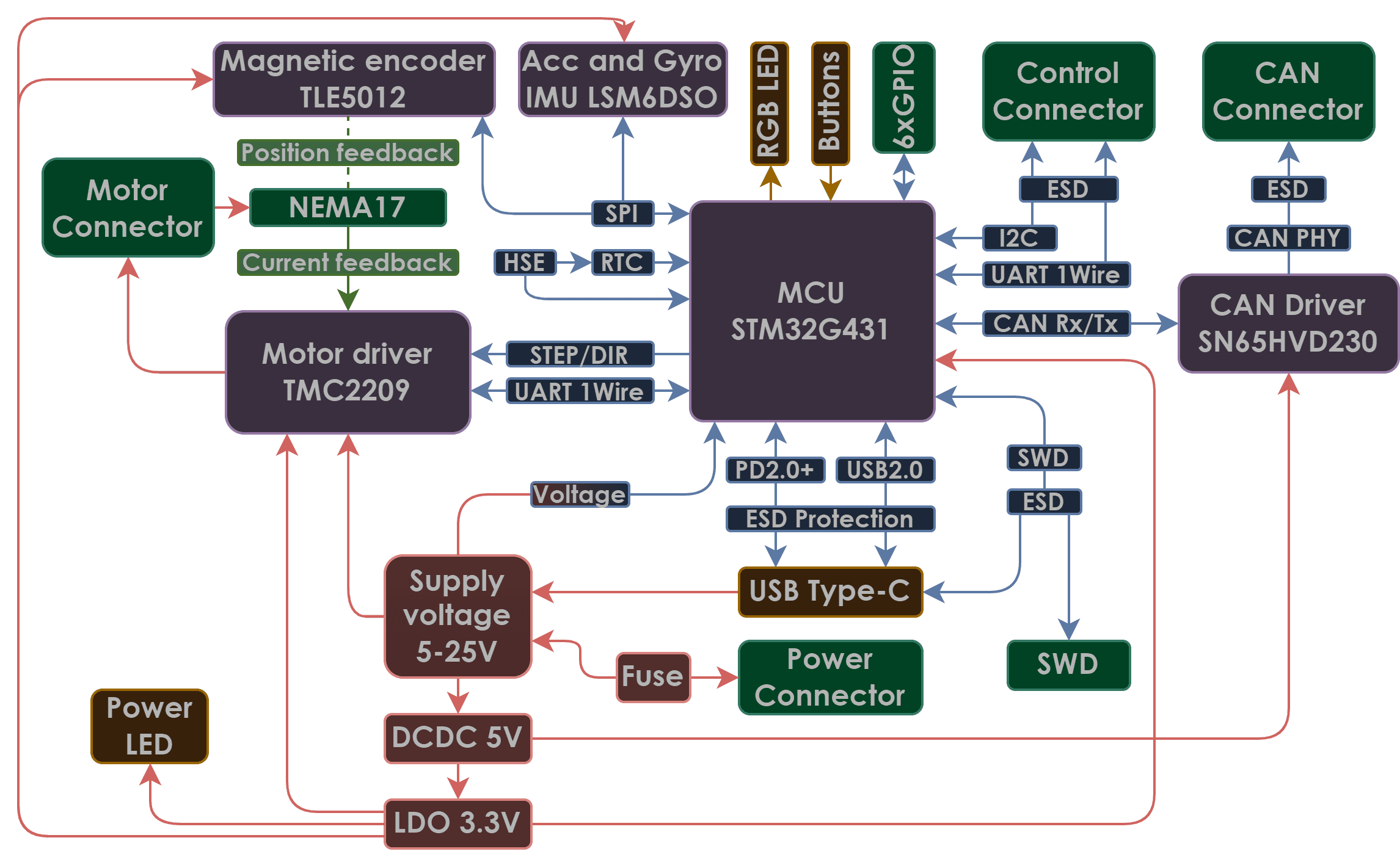
CLN17 serves as the central component of a closed-loop motor system. Its architecture is specifically designed to support nodes that manages motor feedback, process it, and provides real-time responses on the device. The block diagram of CLN17, as shown below, illustrates this architecture and includes various supporting subsystems.
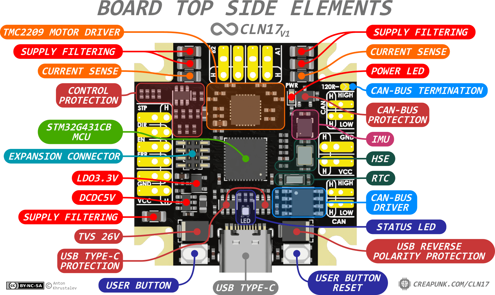
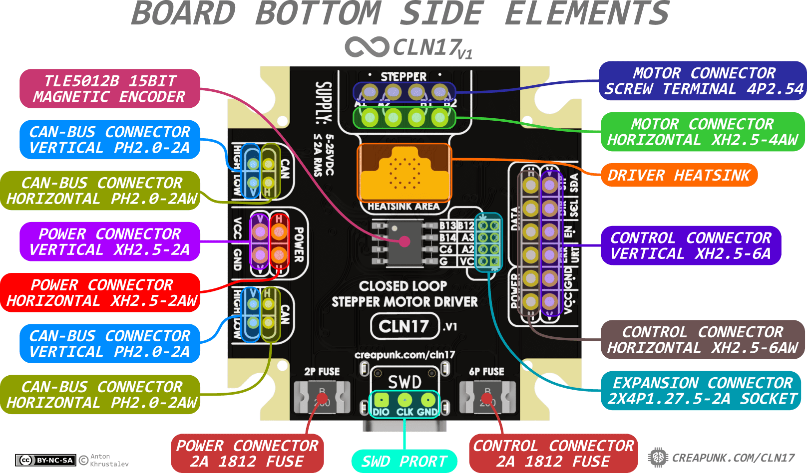
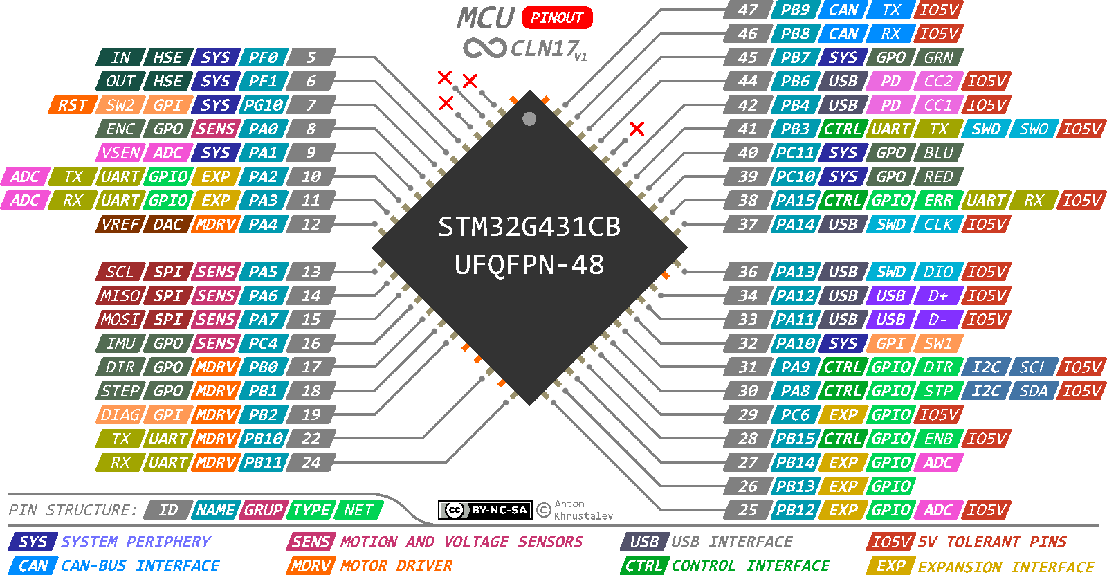
STM32G431CBU pin functions
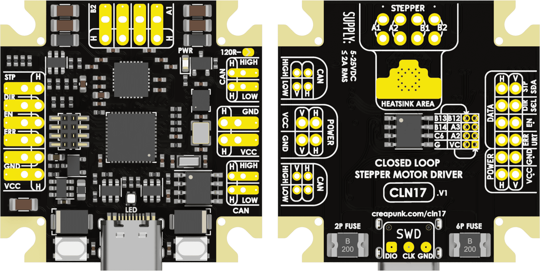
PCBA assembly options
To ensure the driver fits the size requirements and provides efficient cable management, the board supports several primary assembly configurations:
No Connectors: This configuration allows for wires to be soldered directly to the board, resulting in the thinnest board profile.
Horizontal Connectors: Ideal for applications with limited vertical space where soldering isn't suitable.
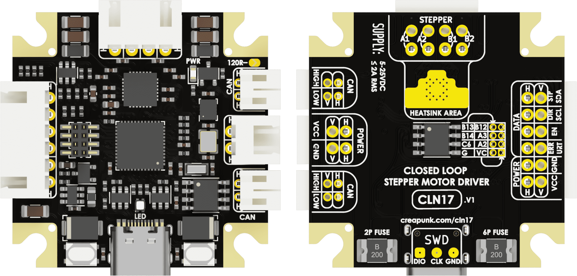
Vertical Connectors: Suited for scenarios where the fitting area is accessible only from the bottom side of the motor.
 Anton Khrustalev