-
1Panel Creation
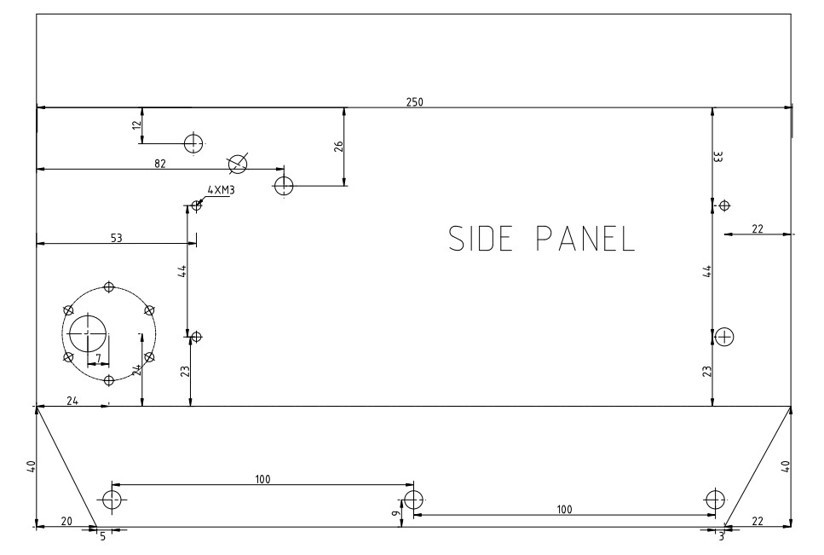
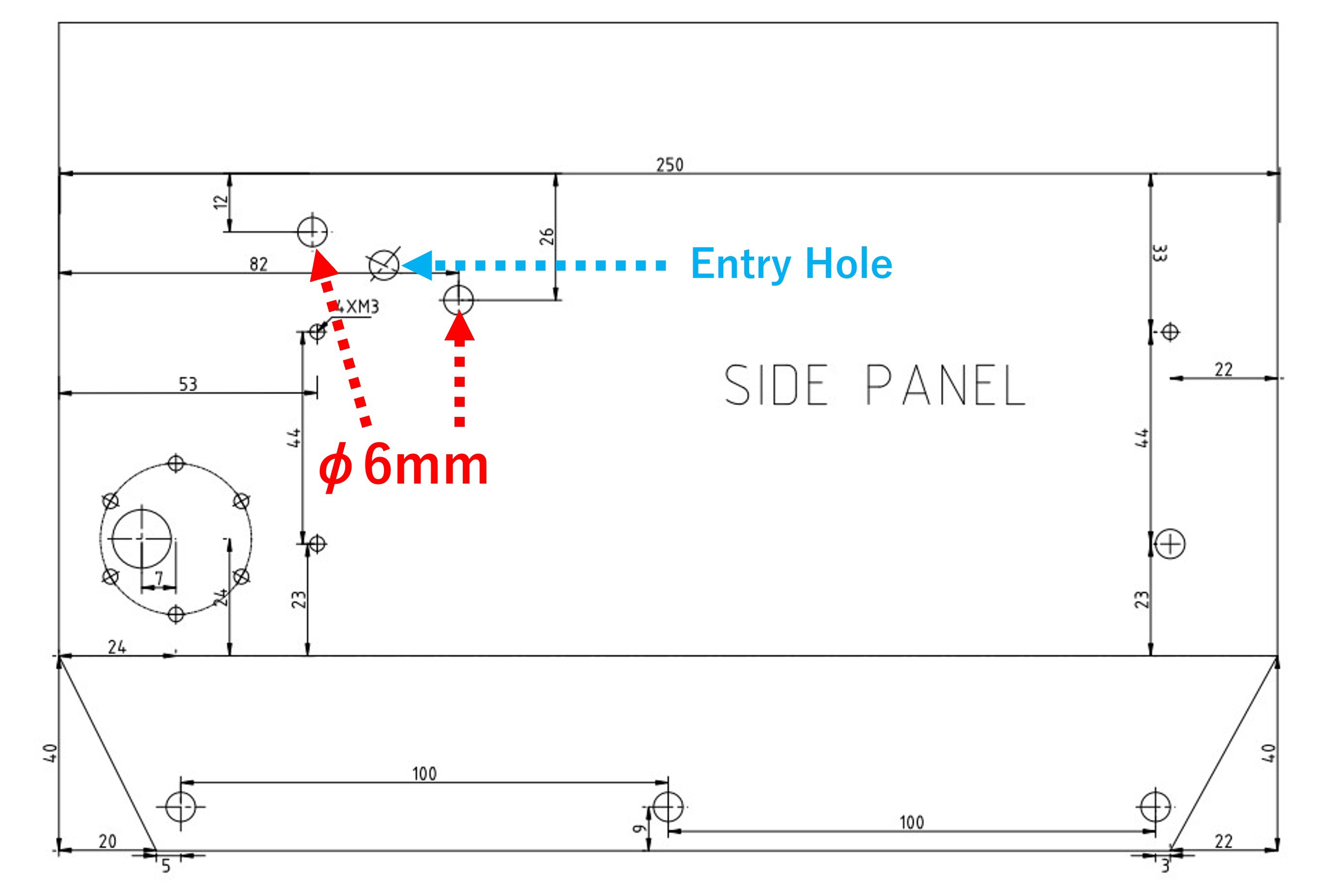
First, we create the panels for the body: there is a 2d cad file in /hardware/cad in the github repository, which we print out in full size. Using this as a template, create the following body panel.
- Top panel x 1
- Bottom panel x 1
- Front panel x 1
- Rear panel x 1
- Side panel x 2
- Crawler cover x 2
Aluminum composite plate or 2mm aluminum plate is suitable for the material. Aluminum composite panels are so easy to process that they can be cut with a cutter, but they are not very strong. Processing aluminum sheets is a little more difficult, but using a sheet metal service will greatly reduce efforts. Tools needed for do-it-yourself machining include a jigsaw that can cut soft steel, 3.2mm, 4mm, 6mm, 12mm, 18mm, and 20mm steel drills, and a rasp file.
![]()
-
2Assemble the chassis
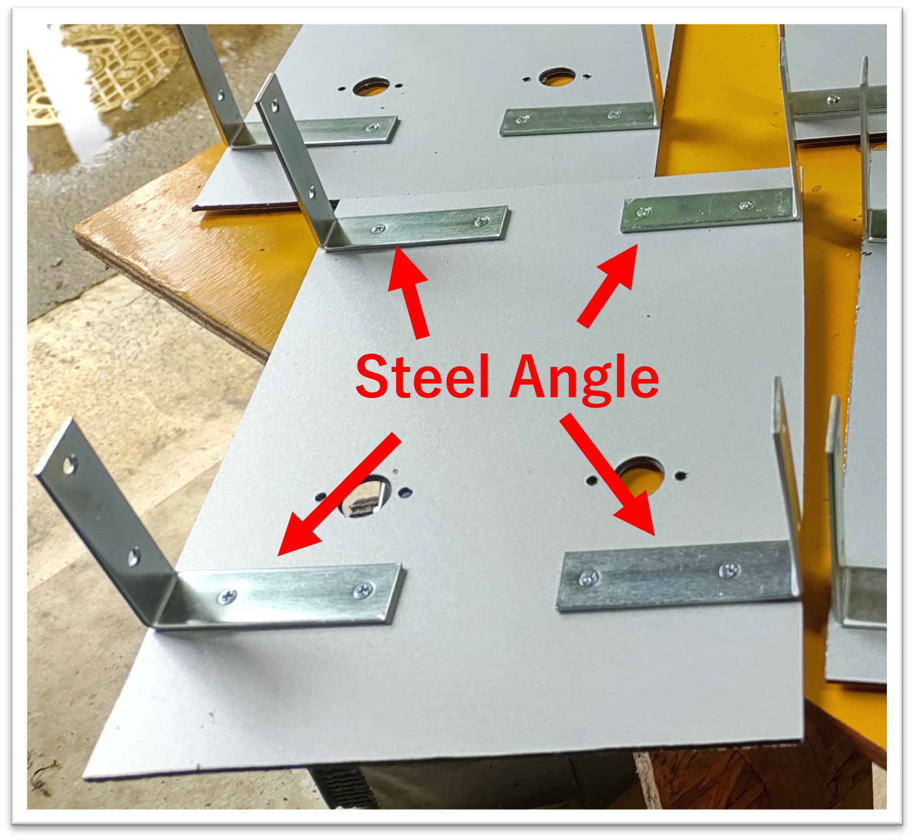
First, bolt on steel angles to secure the bottom and side panels. The front and rear panels are secured with aluminum angles cut short and glued in place. Once the adhesive is dry, fill the gaps with sealant.
![]()
![]()
![]()
-
3Fixing of roller shaft
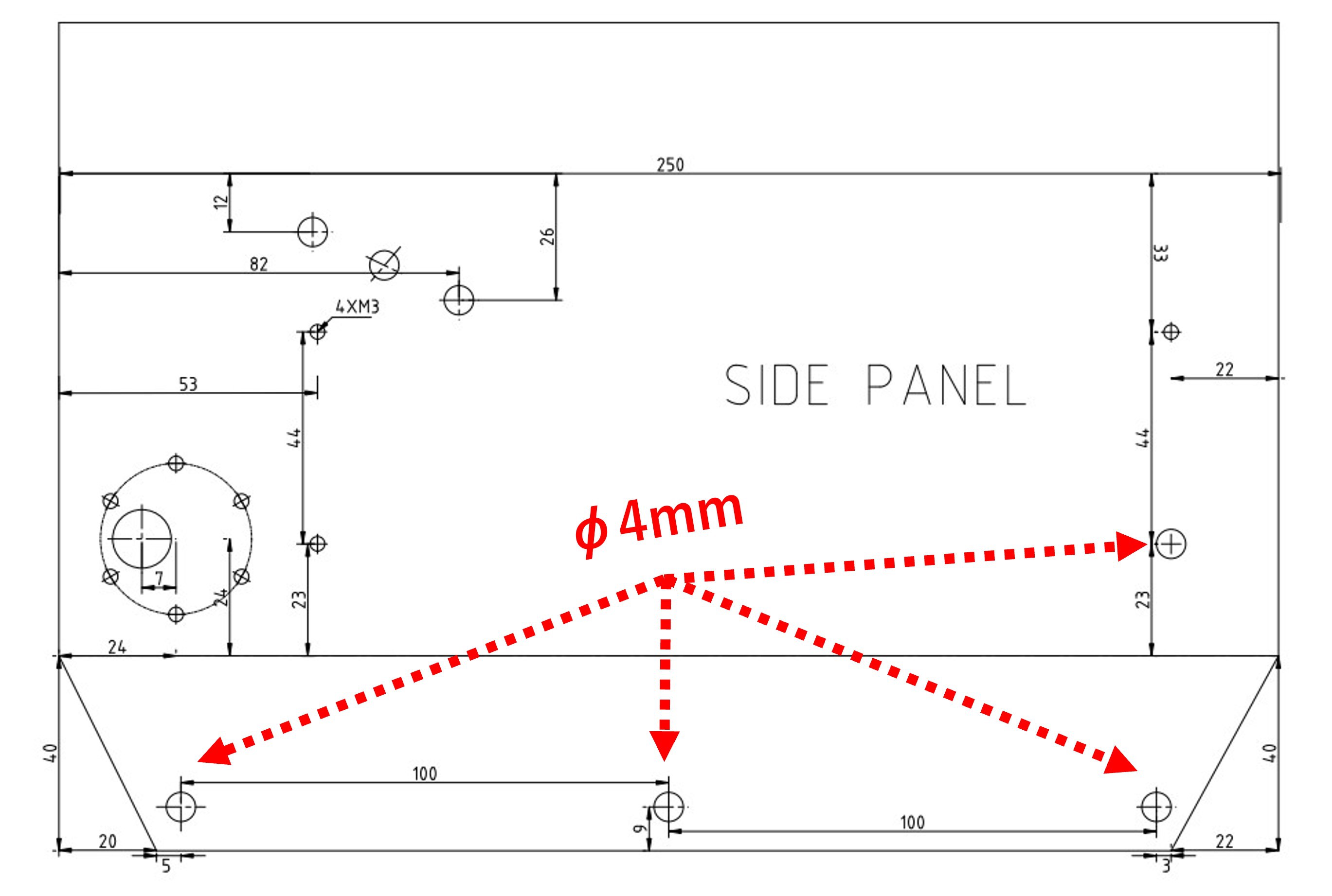
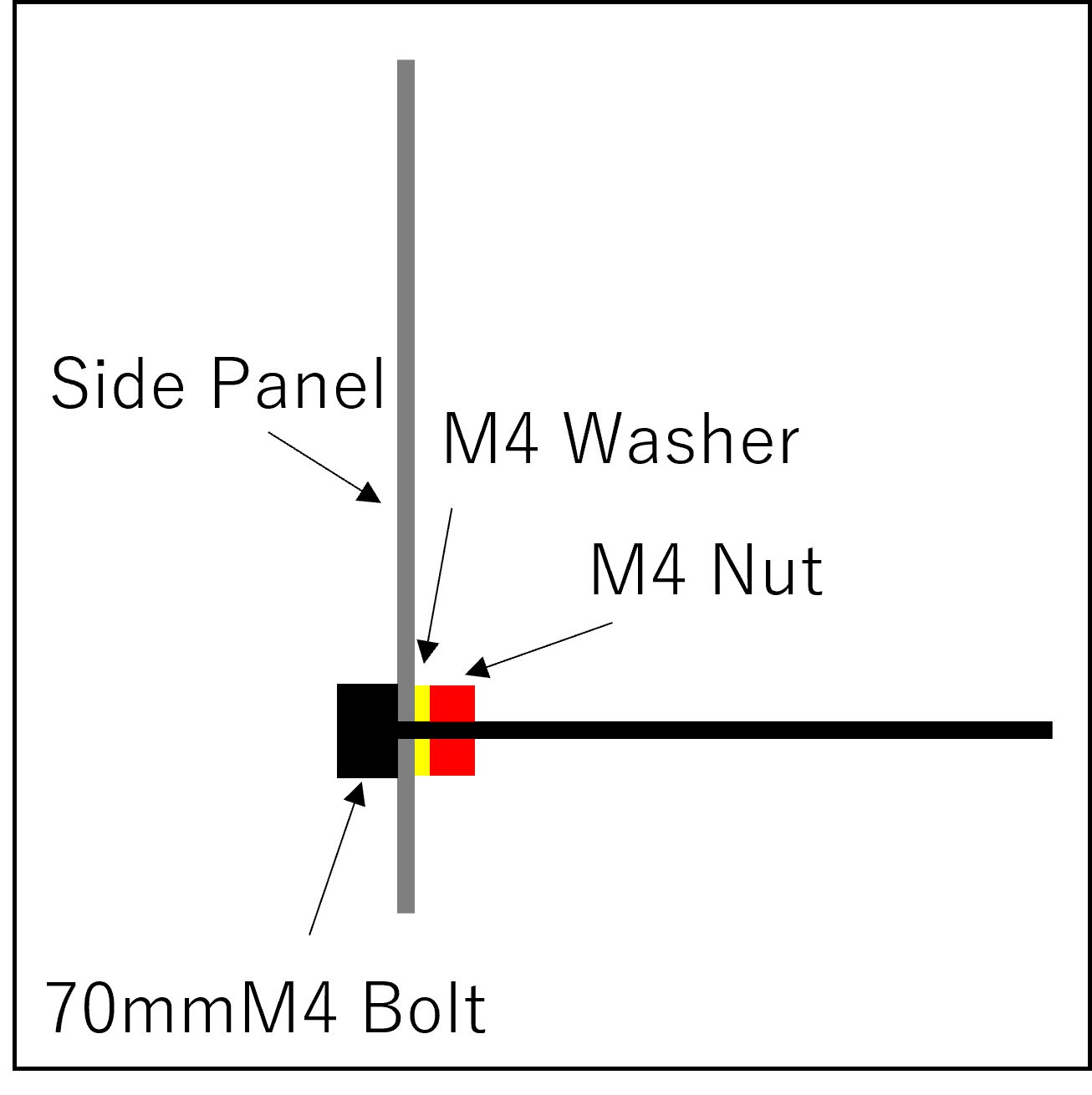
Insert 70 mm M4 bolts to hold the rollers for the crawler and secure with nuts.
![]()
![]()
-
4Install Switch
Fit a 20mm power switch and a 12mm DC connector and bushing for charging to the rear panel. Then solder the cables.
![]()
![]()
-
5Install Motors
First of all, solder a 0.1 μF capacitor to all motors as a bypass capacitor for noise suppression. Next, fasten the RS775 for the mowing blade to the bottom panel with M4 bolts. Also, when the shaft of the RS775 is machined into a D-axis with a grinder, the blade, which is secured with a flange coupling, is less likely to fall off. The 37GB555 motor for the drive is fixed to the side panel with M3 screws. If you are using aluminum composite panels, put washers between them. Otherwise, the panel will not be strong enough and the screws will be stuck in the panel.
![]()
![]()
![]()
-
6Install Battery and Speaker
Attach the battery and speaker to the body with double-sided tape.
![]()
-
7Place the module.
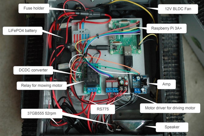
Secure each module on the board with plastic screws or a glue gun and connect the Dupont wire.
![]()
![]()
-
8Make a bumper.
Attach the limit switch to the wooden square bar so that the hinge pops out slightly. Stick half of the tape on the side opposite to the side where the switch is stuck, and stick the other half of the tape on a long, thin board. The bumper is now easily made to keep out rain from above. Once the bumper is finished, screw the stays in place. Then, fix it to the robot body with M6 bolts, pull the wires from the limit switches inside and connect them to the GPIO of the Raspberry Pi, and the bumper is ready to go.
![]()
![]()
-
9Top panel mounting
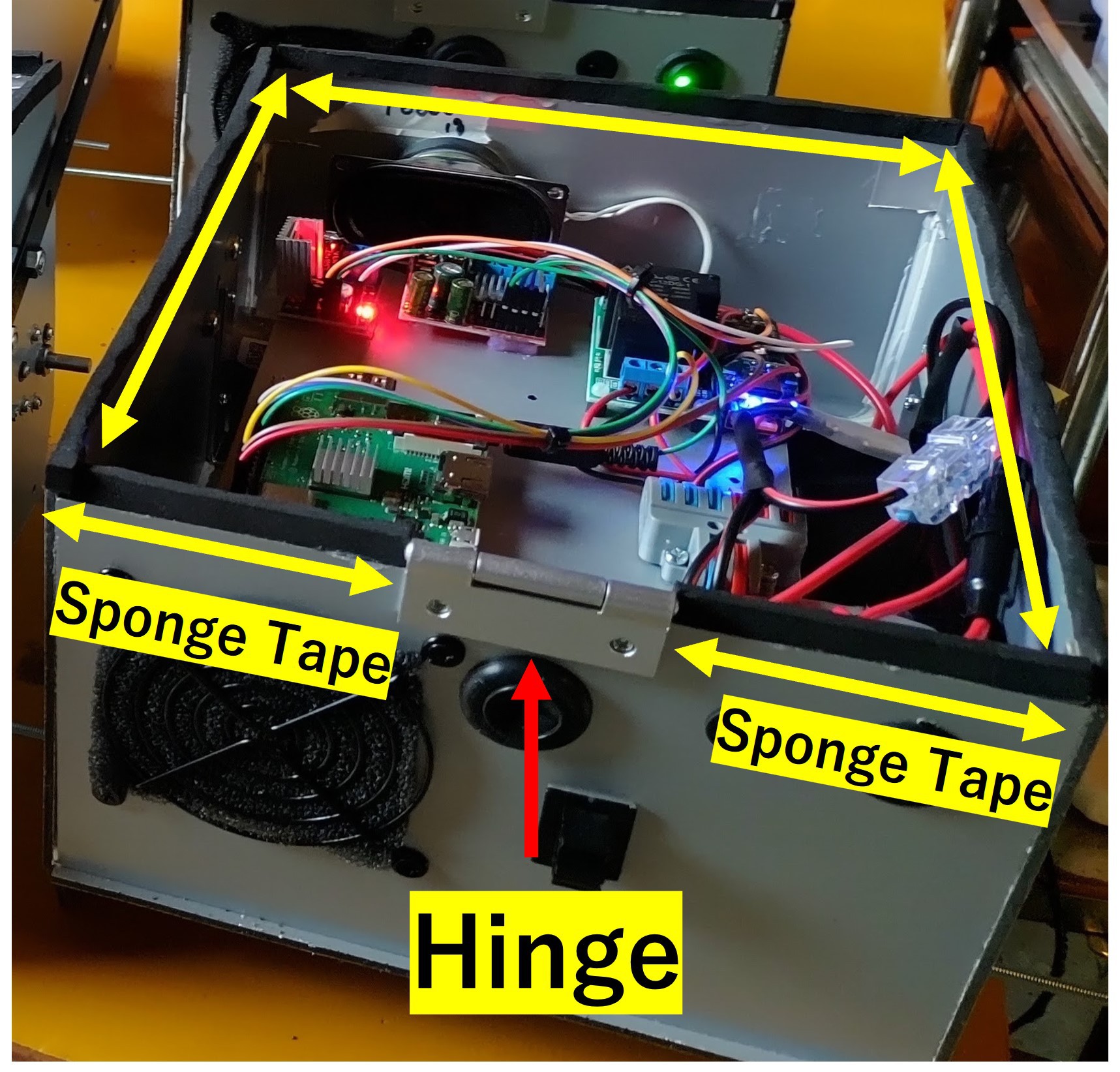
Attach hinges to the rear panel to attach the top panel. Attach sponge tape to the top of the front, side, and rear panels to prevent rain and insect infiltration. Attach small aluminum angles to each side of the top panel with double-sided tape. Then, fix the top panel to the hinges with M3 screws.
![]()
![]()
-
10Camera Mounting
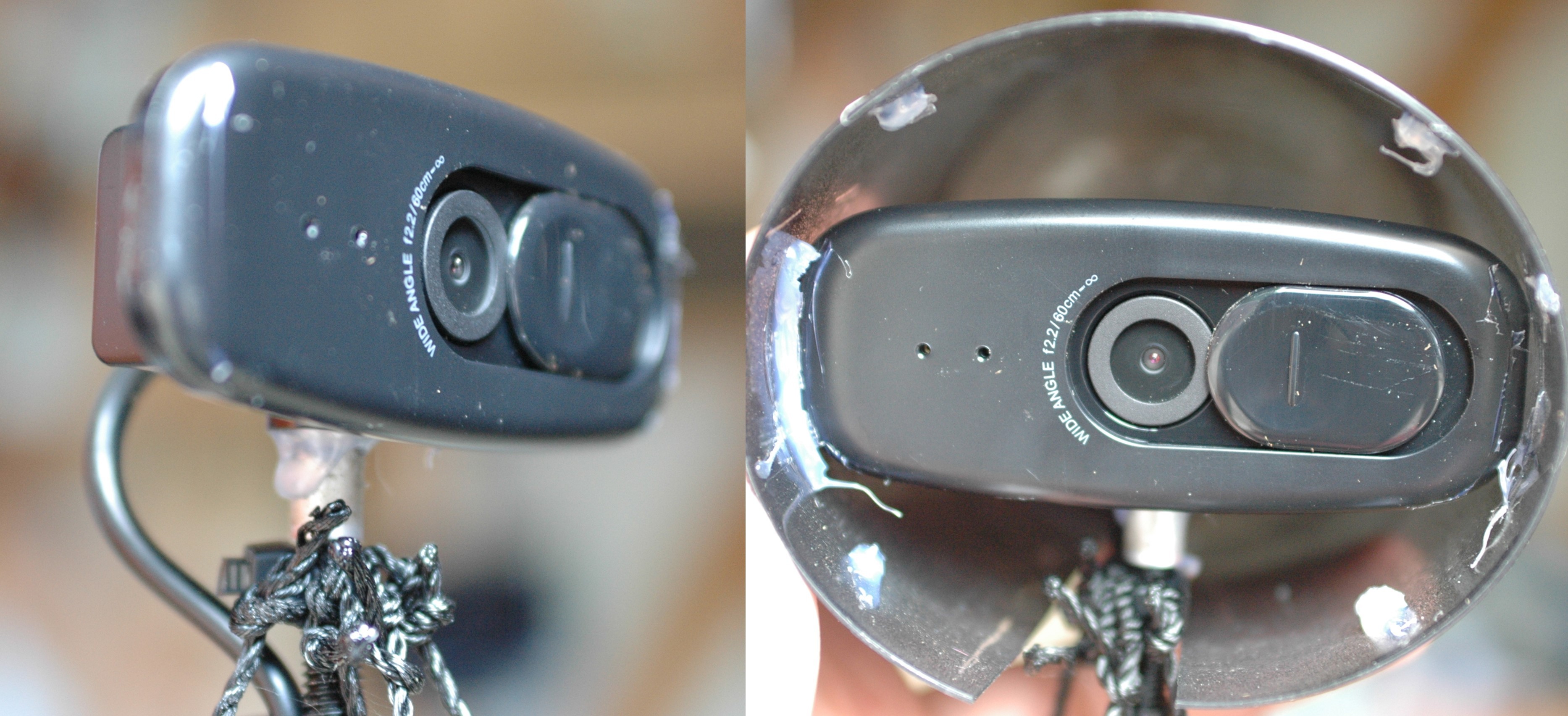
Attach the M6 full threaded rod to the top panel with the two nuts on the top and bottom. fix the USB camera to the end of the rod. you can also use the tripod mounting hole on the webcam. If you want to lower the center of gravity a little, disassemble the webcam and remove the pedestal part and fix it directly to the rod. Next, attach a hood to the camera to protect it from rain and direct sunlight. Insert an acrylic plate with a smoked film attached. Finally, the USB port of the camera is connected to the Raspberry Pi by pulling it inside via the rear panel while securing it with a tie wrap along the rod. To finish, four strands are tightly secured to the end of the rod with tie wraps, creating a loop at a certain length. Tension this loop with reusable tie wraps using holes in the stays or crawler covers.
![]()
![]()
Roktrack - Pylon Guided Mower
A mower not only for your yard, but also for your community.
 Yuta Suito







Discussions
Become a Hackaday.io Member
Create an account to leave a comment. Already have an account? Log In.