-
Fan Control Signal Reverse Engineering
09/11/2023 at 20:17 • 0 comments![]()
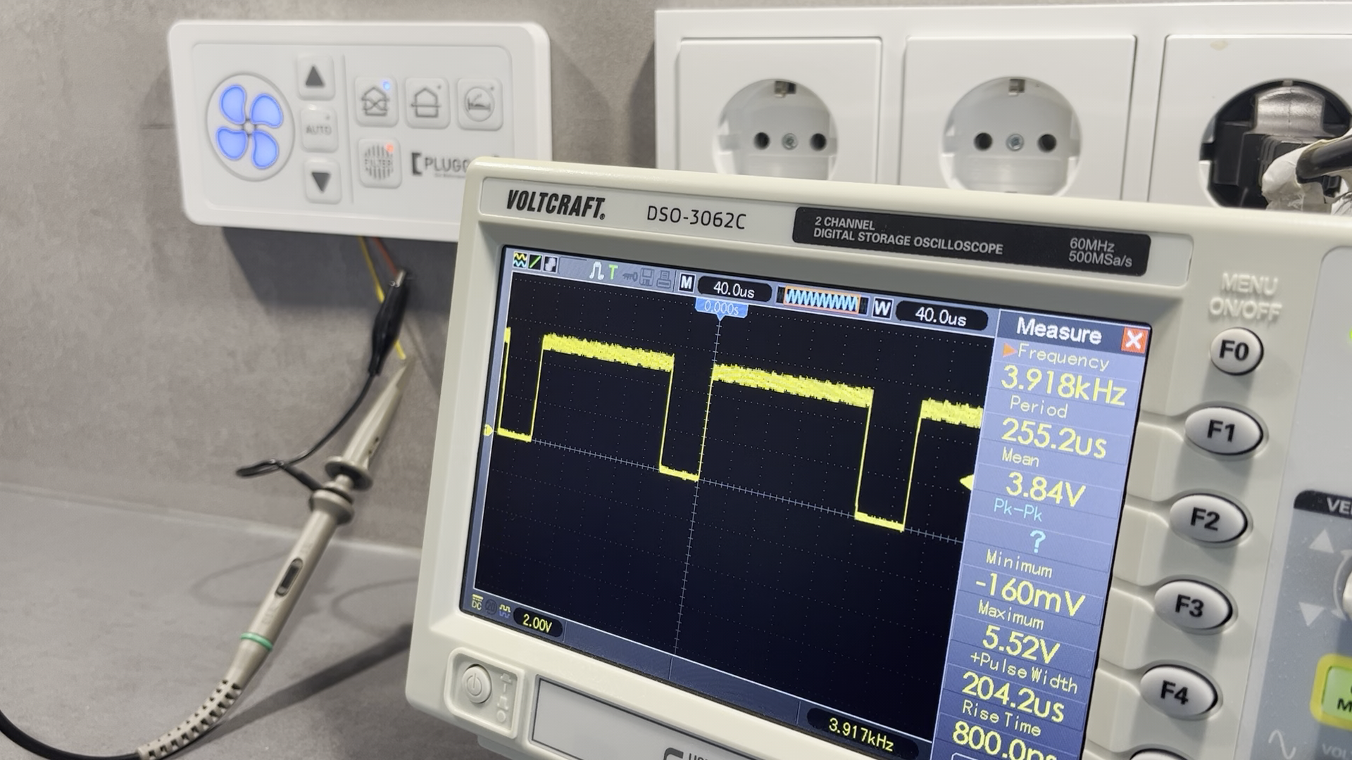
To be able to open and close the shutter when the fan is active or not, the signal of the stock ventilation control bus (pluggit IconVent 160) needs to be analyzed.
Using an oscilloscope reveals a pulse width modulated (PWM) signal with a 5V amplitude and a frequency of 3.915kHz.
When the control unit generates a 50% duty cycle PWM signal, the connected fans will stop operation. A duty cycle above 50% will produce inward air flow, below 50% will prodcue outward airflow.
With this information, the firmware to analyse and replicate the PWM fan control signal can be developed.
-
AutoDuct Block Diagram
09/11/2023 at 19:50 • 0 comments![]()
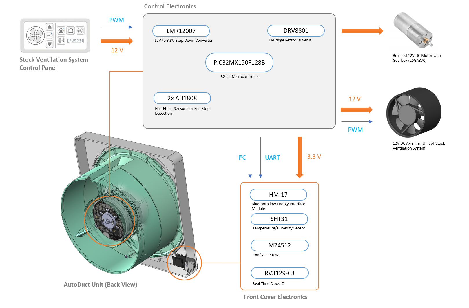
The electronics of the AutoDuct unit is divided into two PCBs: the main control PCB containing the microcontroller, the power supply circuit and the shuttor motor driving circuit is located on the back of the linear actuator assembly. A second PCB is hidden behind the front cover of the unit. It contains the HM-17 BLE communication module, a real-time-clock IC, a configuration EEPROM and a SHT31 temperature/humidity sensor.
The two end stop sensors for the shutter control are placed on a separate PCB and integrated inside of the linear actuator.
AutoDuct smart motorized air duct shutter
Smart motorized air duct shutter with wireless connectivity for decentralized ventilation systems
 Daniel Porzig
