I'm currently working on the feedback signal of the phase detection feature. This signal gets read from the ink droplets which get charged by the phase detection signal.
It took me multiple months until I was able to read anything from the ink droplets. My problem was that I couldn't find anything similar to the "reading of charge on small fast flying droplets".
I read in multiple papers that they used a lock-in amplifier for reading the droplet's charge, which is a pretty expensive instrument that can filter very small signals out of the surrounding ambient noise, by searching for it with the help of a reference signal with the same frequency.
Unfortunately, such an instrument would cost more than all other parts of the project and there also was no IC or ready-to-use module with similar capabilities (besides one from China with a long shipping time).
Another time where @Paulo Campos helped me by giving me the circuit of a CIJ printer's phase detection amplifier.
Thanks a lot, my friend :)
It turned out that the circuit only contained a TL072 Opamp as an amplifier and some filtering - so no lock-in amplifier was needed.
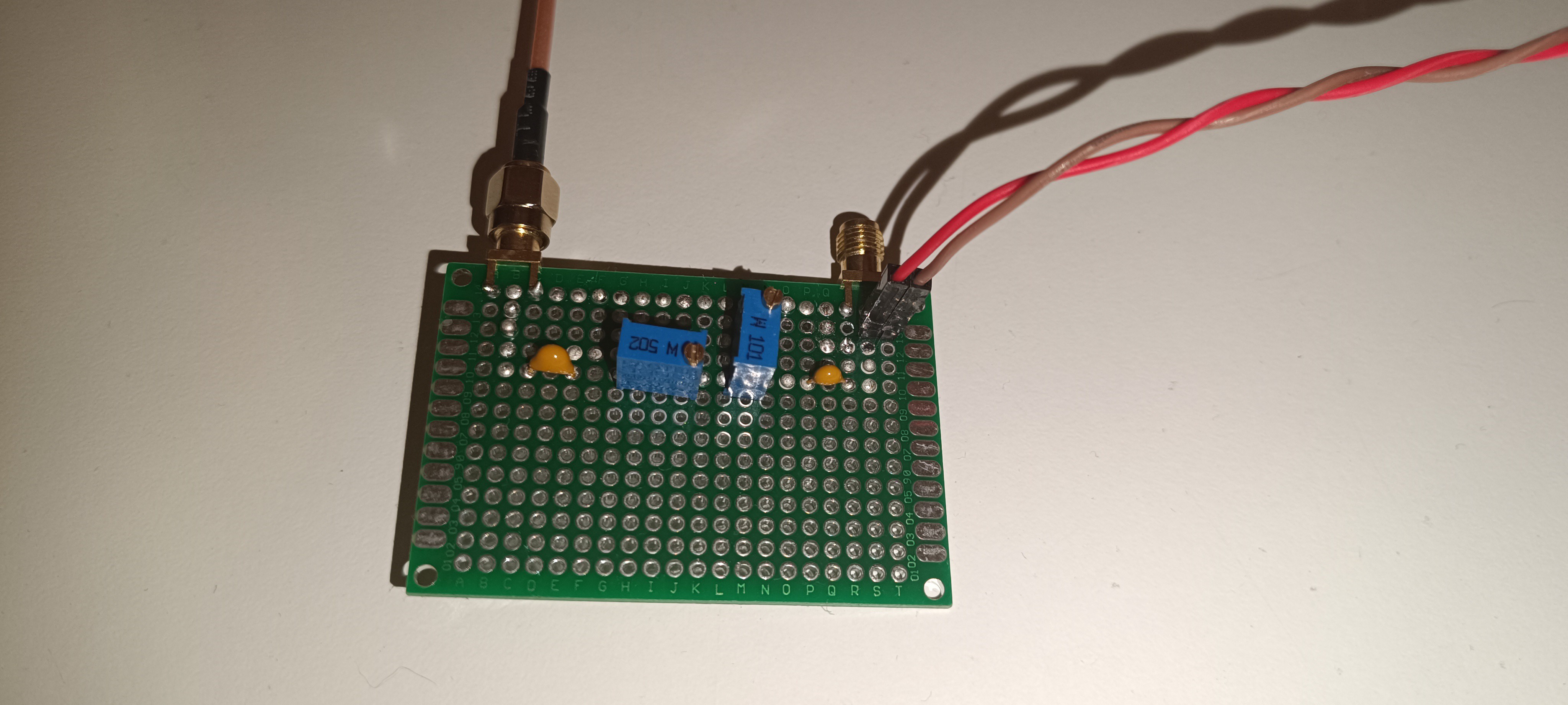
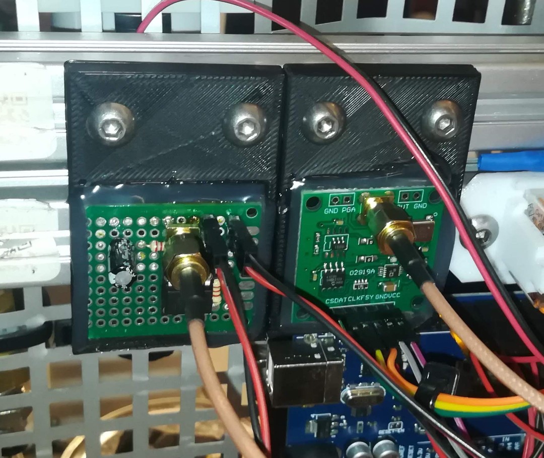
After building and testing the circuit 1:1 which didn't work with my DIY printer, I tried using an "AD620 small signal amplifier module" in combination with a self-built bandpass filter designed for 50kHz, which finally gave me a signal.
AD620 Small Signal Amplifier
50kHz Bandpass Filter
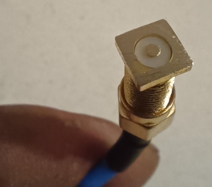
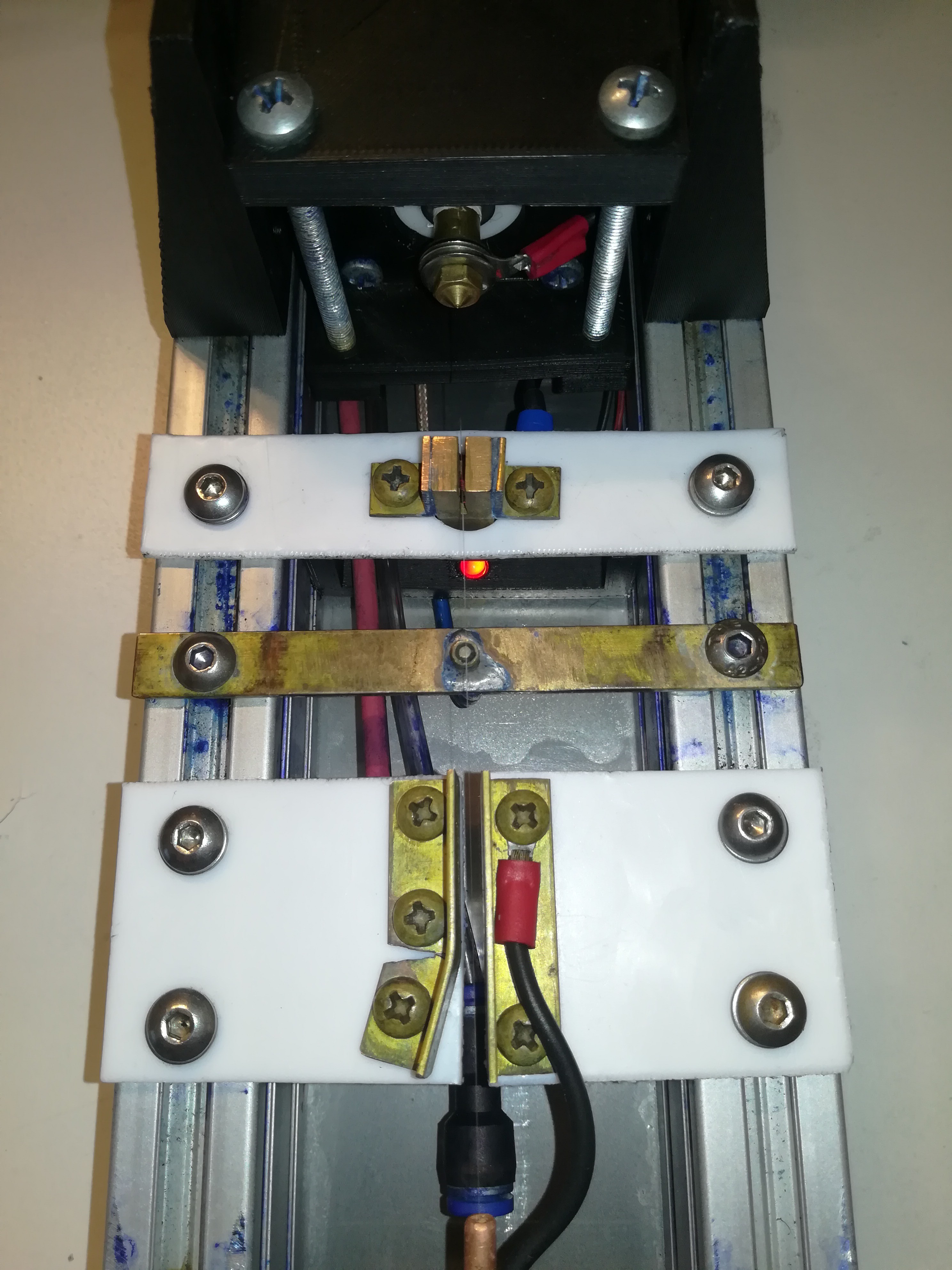
For the sensor or probe for reading the signal, I used a long SMA solder connector, from which I cut off and sanded down the legs to get a flat surface with the shielding on the outside and the probe pin in the middle. For the sensor, shielding is very important, because the signal that gets read from the droplets is smaller than the ambient noise and also smaller than the phase detection signal itself, which gets radiated out from the charge electrode.
Without good shielding, the sensor would pick up the signal from the charge electrode instead of the signal from the droplets.
Sanded down SMA solder connector as Sensor/Probe
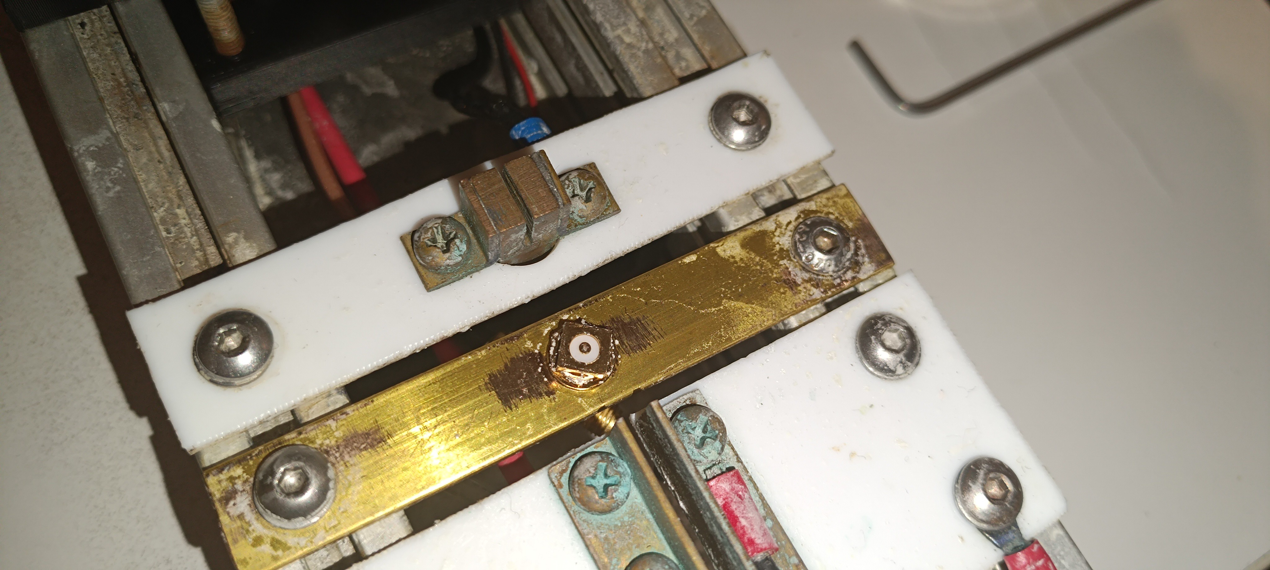
Phase Detection Sensor on the Printhead
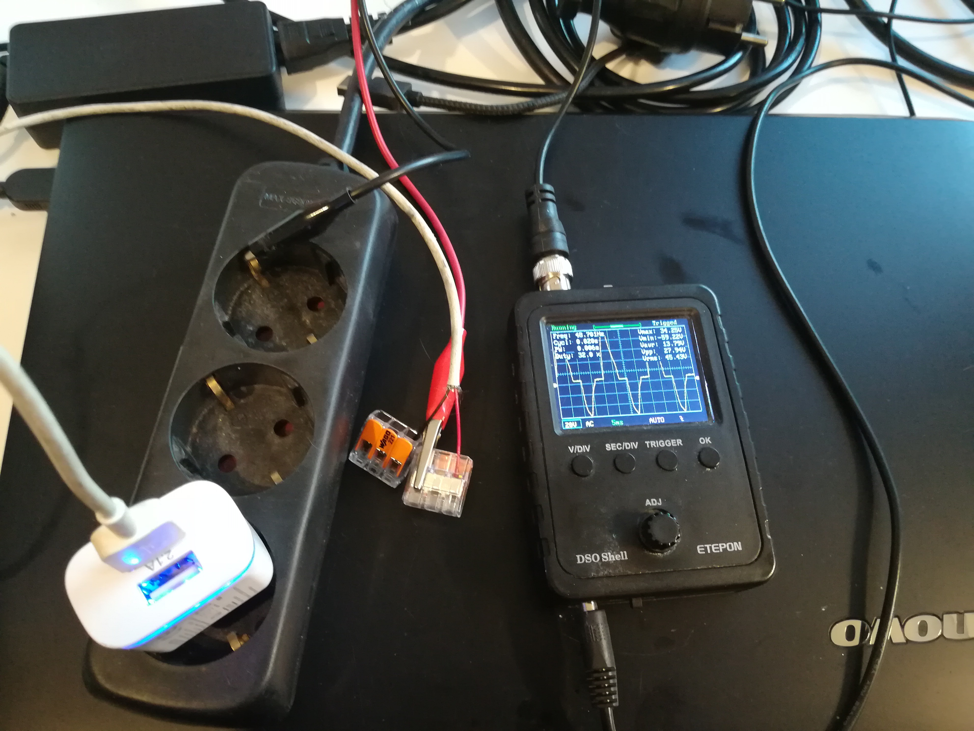
With the new setup, I could finally get some signal that reacts to the presence of the ink droplets.
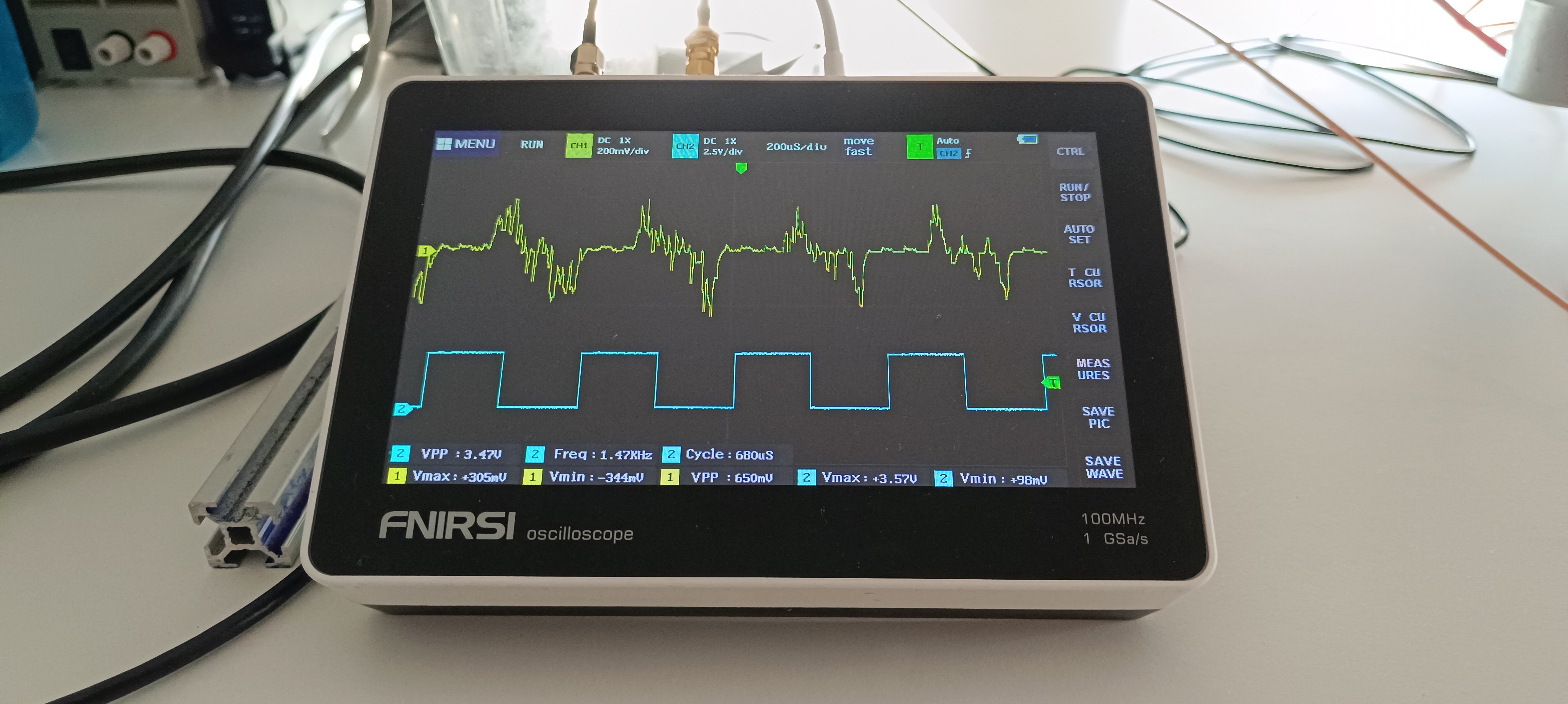
Trigger Signal in blue, Feedback Signal in yellow
When I stopped the ink stream by blocking the nozzle with my finger, the signal disappeared and when I turned off the piezo, the signal got replaced by noise. The amplitude of the signal got decreased when the ink droplets passed the sensor at a higher distance and got increased when the ink droplets passed the sensor at a lower distance.
So, it should be the signal I'm looking for since November last year :)
But the signal is not perfect, yet. Normally the phase detection feedback signal has the shape of a hedgehog with the highest voltages in the middle and the lowest voltages on the outside. It shouldn't go negative either and it should also be more stable.
So, there will be some improvement needed until it can be used for selecting the right phase based on it.
However, having this signal gives me something to look at while adjusting things on the printer and doing improvements. I can change something and look at how it affects the signal which gives me a way of feedback that I never had before.
Here are some videos about ink stream detection testing based on the feedback signal:
It's nice to have something to show about this project, again.
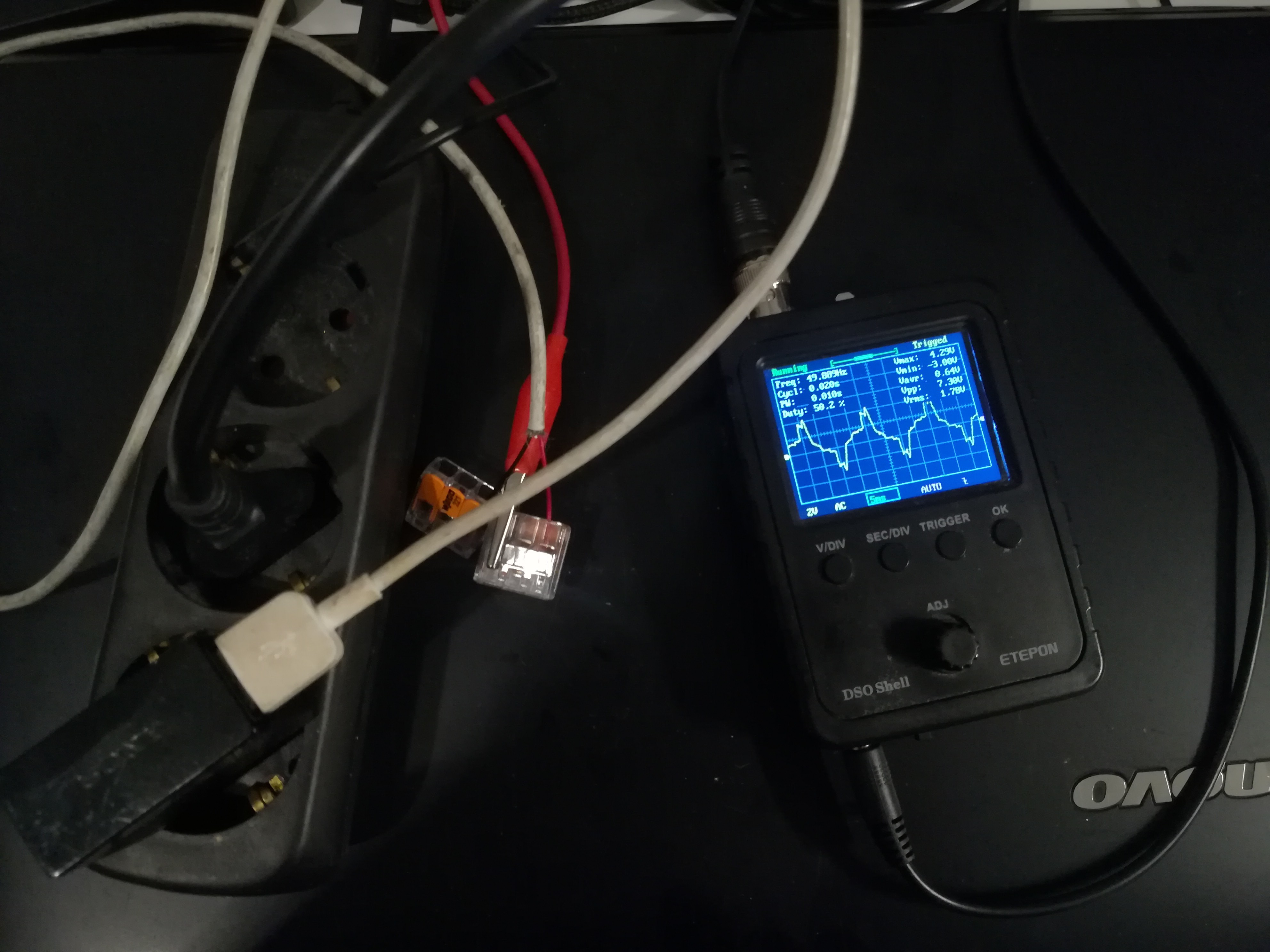
Here is another test:
This time with 48V instead of 24V piezo drive voltage. In the video you can see that by adjusting the drive voltage the feedback signal also changes.
Thank you very much for your interest in my project :)
At the time when I started working on the phase detection signal generation, I used an AD9833 for generating a sine wave that drives the piezo and an LM393 Schmitt trigger circuit that converts it to a square wave, which drives the strobe LED that makes the droplet formation visible to the naked eye.
LM393 Schmitt Trigger on the left, AD9833 Signal Generator on the right
Unfortunately, this setup was not suitable for generating the phase detection signal, so I had to find another solution.
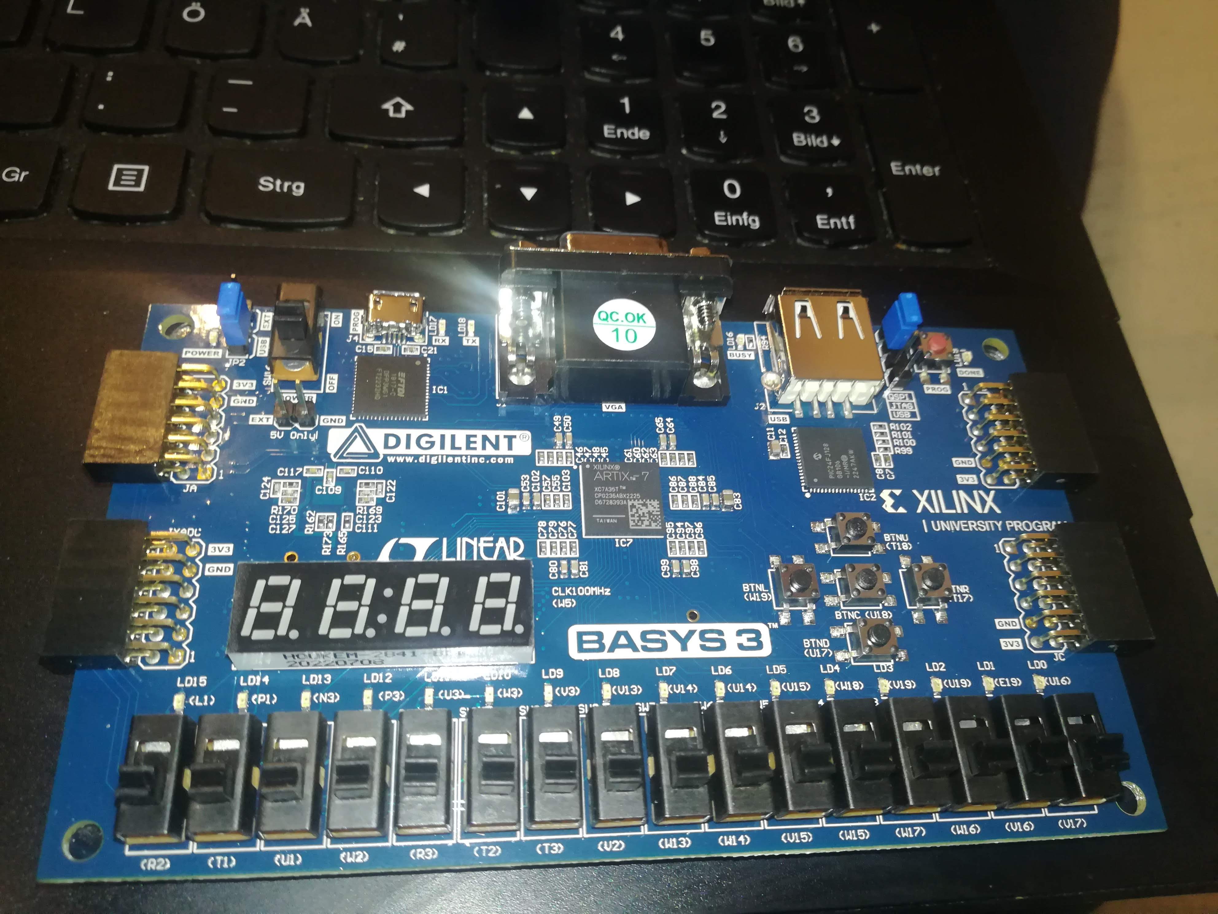
Commercial CIJ printers use FPGAs for their signal processing and generation, so I started by buying a beginner FPGA board - the BASYS 3.
BASYS 3 FPGA Development Board
After trying out some tutorials and examples, I quickly realized that using an FPGA is not the best choice for a "low-cost, easy-to-build" open-source project, because of its cost and complexity.
So, another solution was needed.
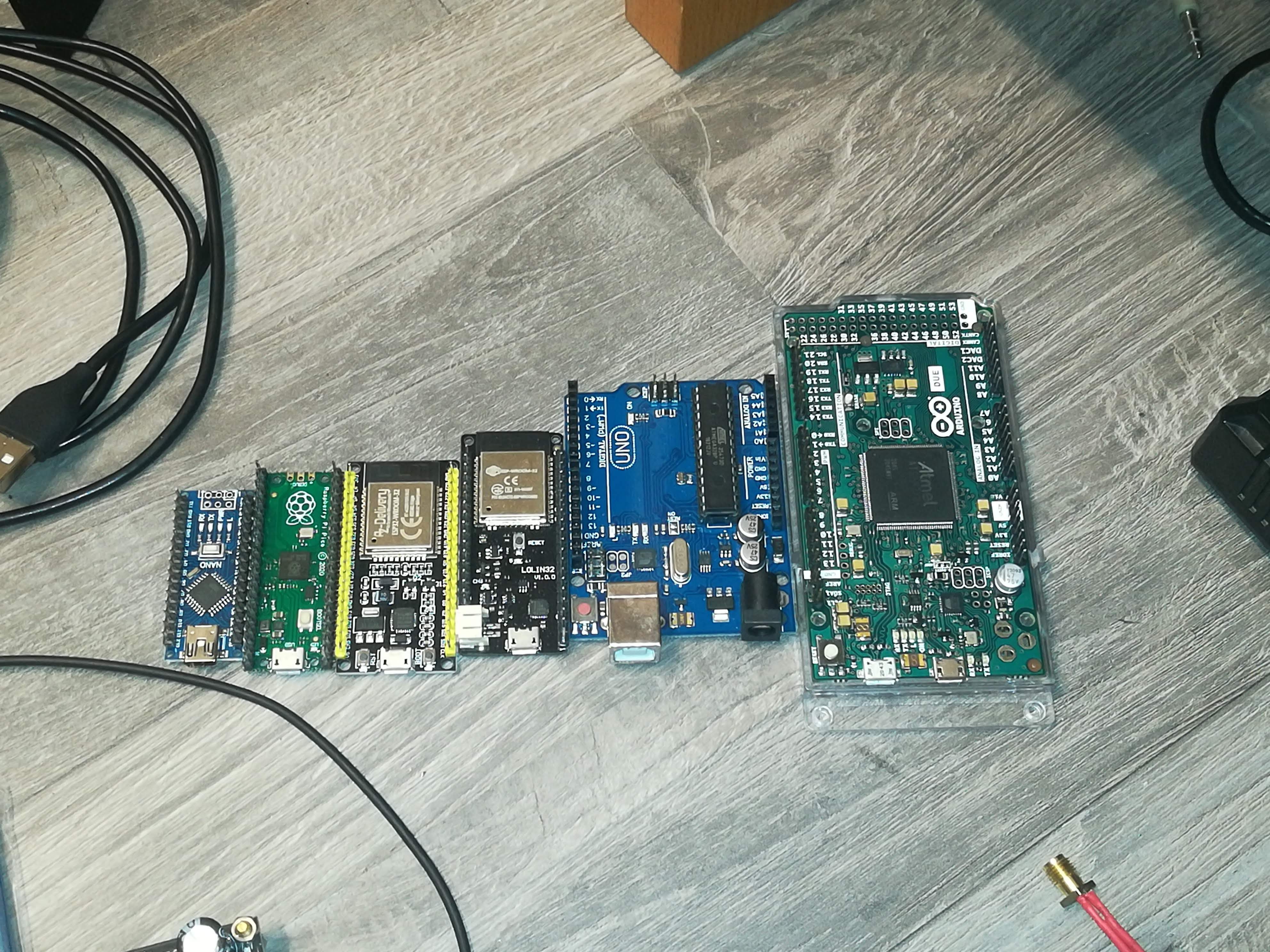
A photo of all microcontroller boards that I tried out for Signal Generation
After the FPGA, I tried out multiple other microcontroller boards until I tried out the ESP32, which was able to generate pulse sequences like the phase detection signal with its RMT feature.
Unfortunately, I couldn't start different output channels at the same time with it. Even if there seems to be a synchronization manager feature for RMT, I couldn't find out how to get it working.
While searching on the web for infos about the ESP32's RMT feature, I read about the Raspberry Pi Pico's PIO (Programmable IO) feature, which turned out to be a better solution for signal generation than the ESP32's RMT feature.
The PIO feature of the Pico is intended to be used for coding your own communication interfaces to add functionalities to the Pi that it doesn't have out of the box.
The Pico features 8 so-called "state machines" with each of them being able to perform simple operations independently from the main CPU and other state machines.
They run a custom instruction set (no C++ or micropython) of which each instruction takes one clock cycle to be performed, which makes them ideal for time-critical tasks like communication or signal generation for this printer project.
They also can be synchronized, so that all signals needed for the printer's operation can have the same clock source and starting time.
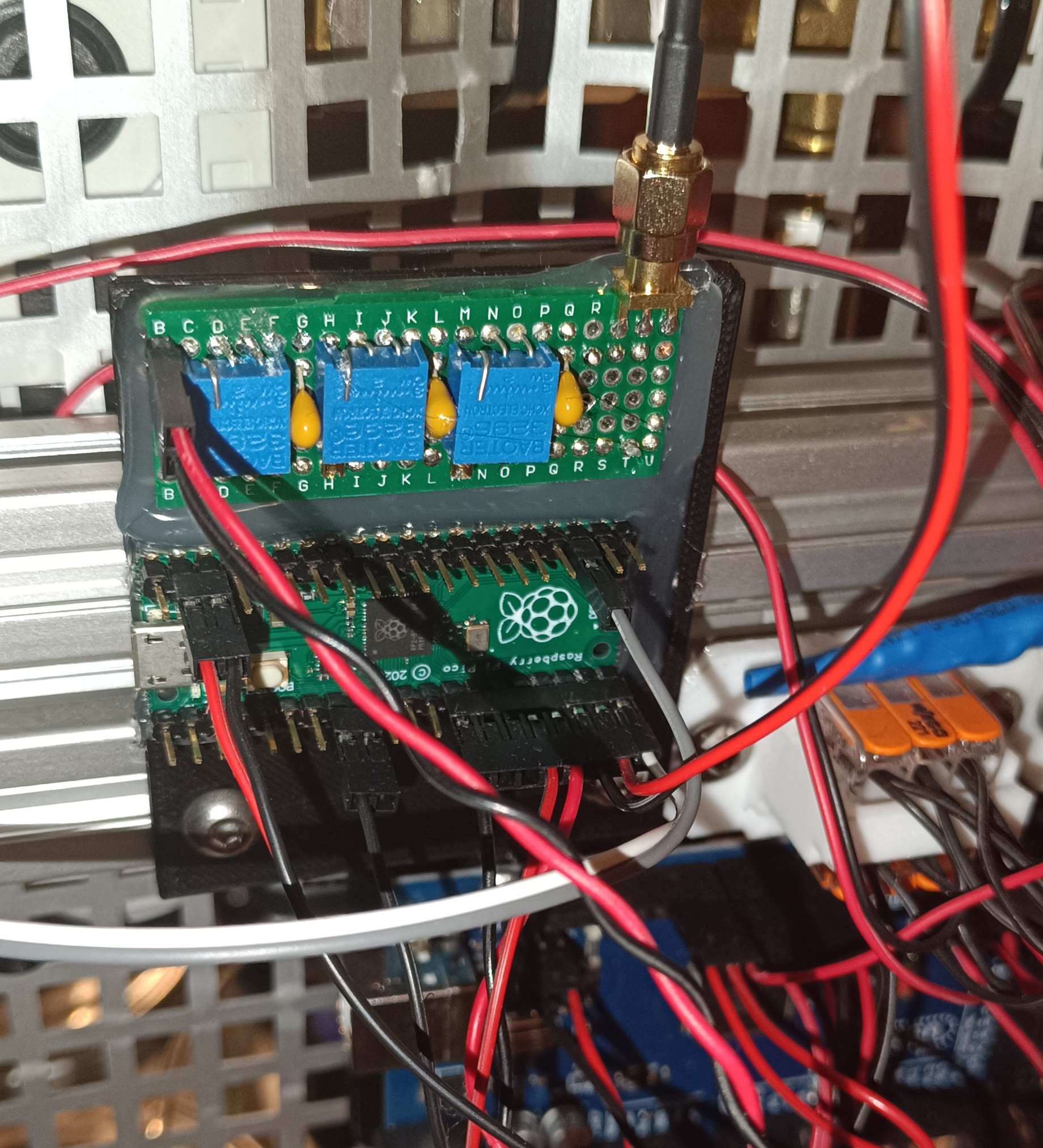
Raspberry Pi Pico and RC Filter for generating a Sine Wave out of a Square Wave
With the PIO feature, I generated the following 4 signals:
- Piezo Drive Signal 50kHz 20us
- Strobe LED Signal 50kHz 20us
- Phase Detection Signal 1.47kHz 680us
- Oscilloscope Trigger Signal 1.47kHz 680us
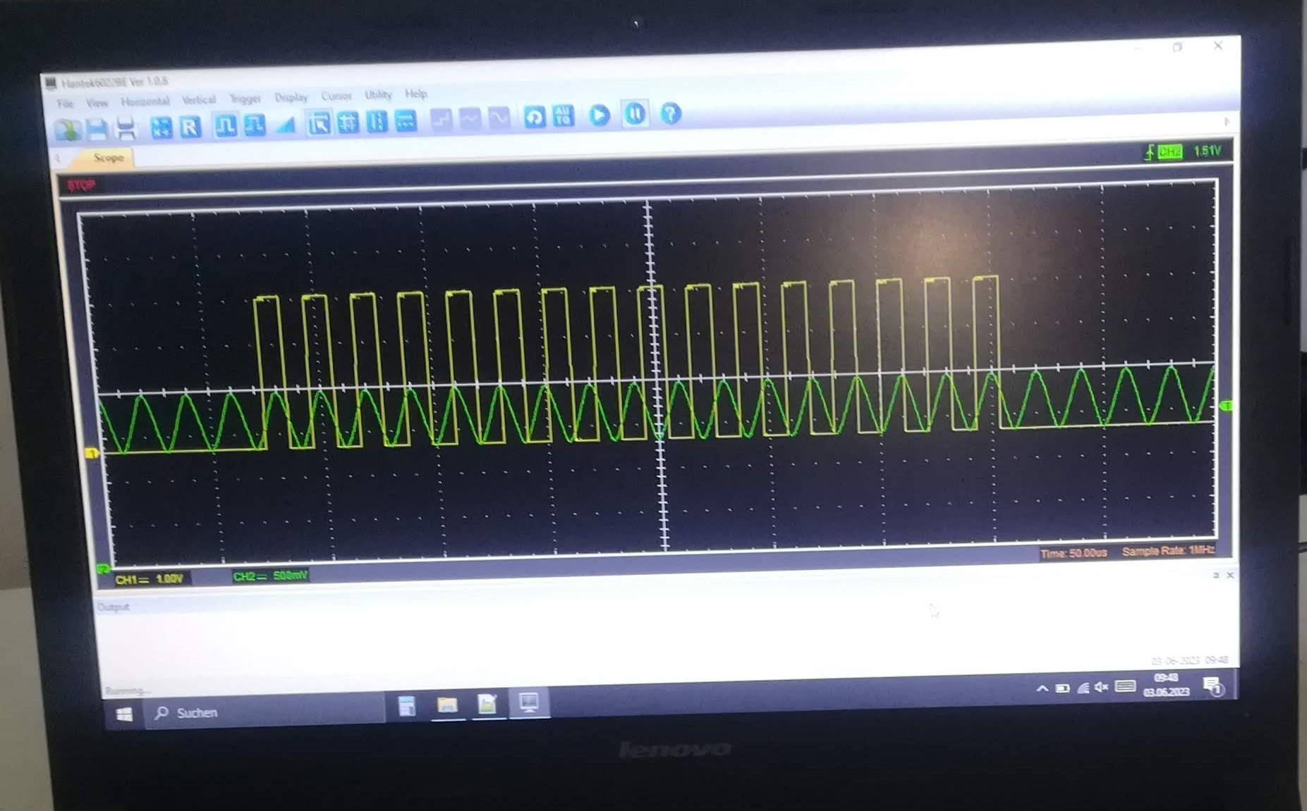
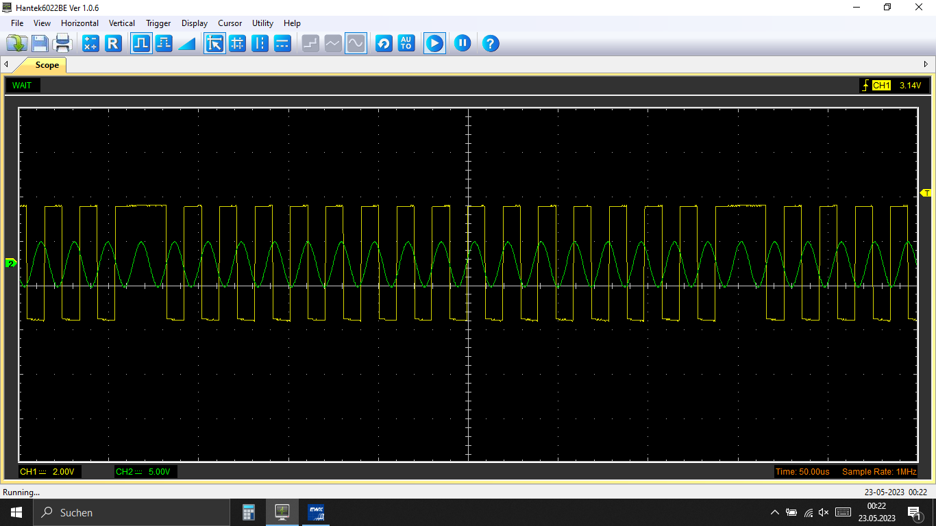
Because the output of the Raspberry Pi Pico is a digital signal with either around 0V or around 3.3V it was needed to filter the piezo drive signal with an RC filter to get a "close-to-sine-wave-shaped" signal.
In yellow 0V to 3.3V Phase Detection Signal, In green Piezo Signal when it exits the RC Filter
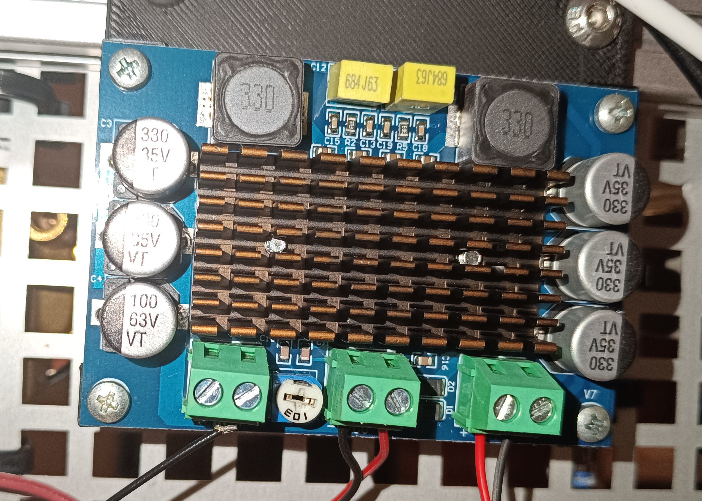
At the current state of the project, the piezo signal gets fed into a 24V 100W audio amplifier, which amplifies it and sends it to the piezo ring at the nozzle.
24V 100W Audio Amplifier for Driving the Piezo
Maybe I will replace the audio amplifier with a dedicated piezo driver, later in the project to get a better drive signal. The square-to-sine wave RC filter is also not optimal and could later be replaced by something else.
Something like a circuit where you can feed in a 0V to 3.3V square wave and get a 100+V sine wave out would be perfect...Maybe later...
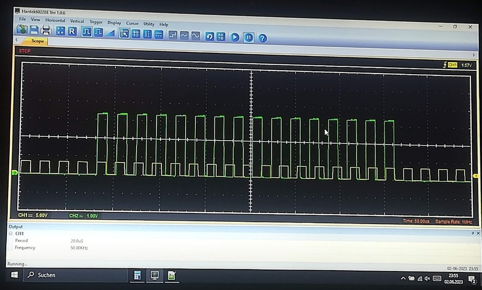
For the strobe LED I'm currently using a dedicated pin, which isn't really needed, because I could also just use the piezo signal. Both signals are the same when they exit the Raspberry Pi.
Strobe LED Signal in yellow, Phase Detection Signal in green
However, at the moment the output is not needed for something else and so it's possible to connect the strobe LED directly to the pin without additional wiring.
Strobe LED for making Droplet Formation visible
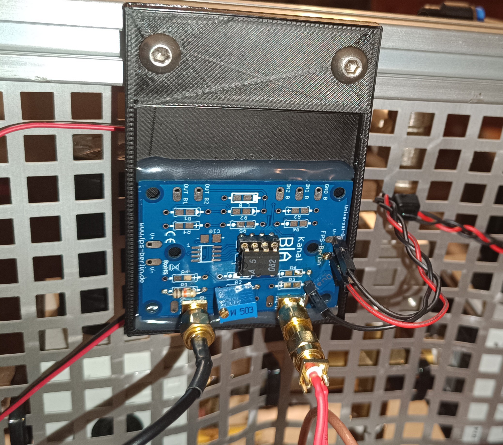
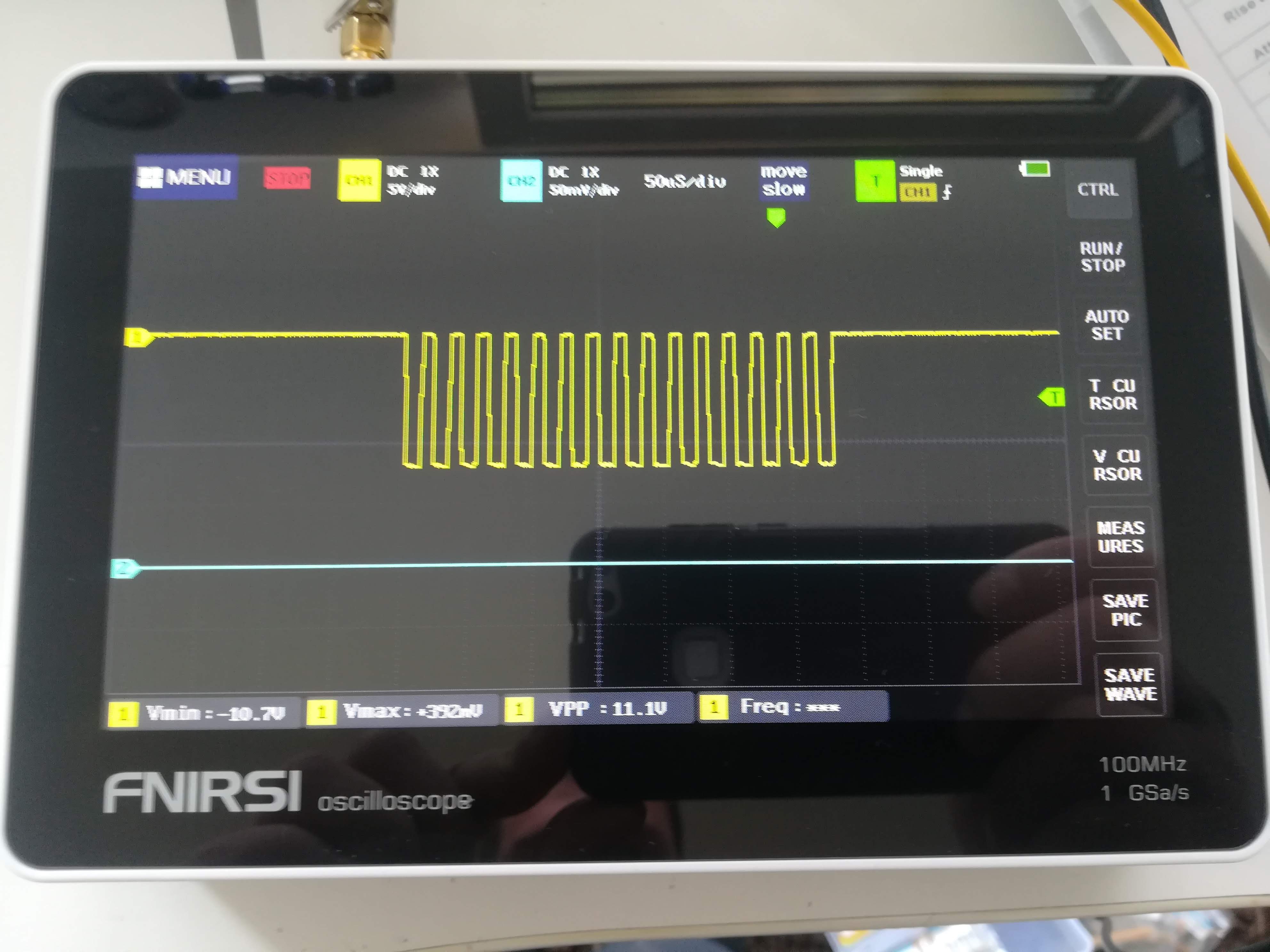
The phase detection signal is passed to an inverting amplifier circuit that amplifies and inverts it from 0V to 3.3V to around 0V to -12V.
Inverting Amplifier Circuit using a TL082 OpAmpPhase Detection Signal after the Inverting Amplifier
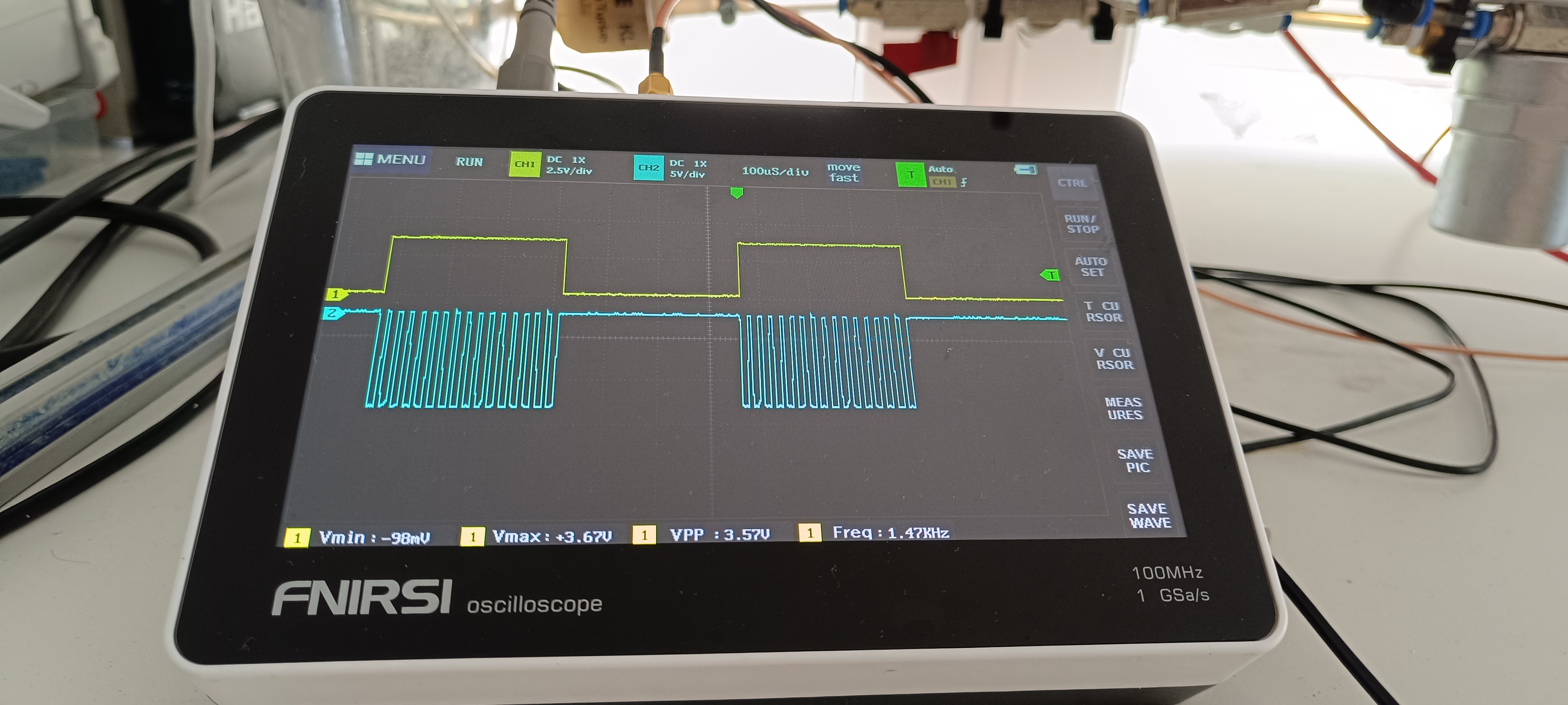
I added the trigger signal because my oscilloscope can not trigger the phase detection signal right - it keeps jumping back and forth.
The trigger signal is just a simple square wave with the same period as the phase detection signal of 680us, which is suitable for triggering the oscilloscope without any jumping.
Trigger signal in yellow, Phase Detection Signal in blue
At the moment I'm just using these 4 signals, which leaves me with another 4 PIOs for performing other tasks.
One will be needed for the feedback signal of the phase detection feature, about which I will write more in the next log and another one will be needed for the timing of the charging signal that charges droplets with a high voltage for printing.
I have no final plan, yet, for how the selection of the right voltage for print charging should work in the end. There are also other things that have to work first before I can start working on this.
But my idea at the moment is to send a timing pulse from the Raspberry Pi Pico's PIO output with the correct phase setting when it gets triggered from the main CPU.
It's not essential that the droplets which print a vertical line are droplets that form right after each other. It would be beneficial for printing speed, but it is more important to get it working at all, so if there would be "spaces" of uncharged droplets between charged droplets, it wouldn't be a problem, either.
So, the Pi has to get the vertical line pattern via serial from a PC or printer controller. Then it has to convert and send them for example via SPI or I2C to a digital potentiometer which controls the gain of an amplifier which controls the print charging voltage. Finally, it has to trigger the PIO which sends the trigger pulse to a transistor which then charges a single droplet.
If this process would take longer than 20us (better 15us, to have some margin) it would miss the opportunity to charge the following drop, which like I said before, wouldn't be a problem, either.
This was just a thought and the final solution for that could look completely different...
More about the Phase Detection Feedback Signal in the next Log.
I started my work on the phase detection feature by reading the manual of a Videojet Excel 170i which I bought for testing. I read that it uses a 420us long 10VDC pulse for charging 28 droplets, which later get analyzed for selecting the right phase. This printer is using a piezo frequency of 66kHz which has a period of around 15us. 420 divided by 15 equals 28 which explains the numbers. This printer can select between 4 phase settings. It uses the gutter instead of a dedicated probe for reading the charge of the droplets. Unfortunately, it was not described how the printer analyzes the signal, so this did not help me much.
At least I learned from it that phase detection is an important part of CIJ printing and that it is done by sending a signal to the charge electrode which later gets read from the droplets to get a feedback system.
The remaining question at this point was, what a phase actually is and how the signal could help find out the right phase.
Fortunately, @Paulo Campos could help by telling me about an improved method that uses 16 instead of 4 possible phase settings and a phase detection sensor/probe instead of the gutter.
Thank you Paulo for helping me again :)
Now I had to implement Paulo's method into my DIY printer, which is no 1:1 copy of another printer, but my own design, so there was some work needed to get it going.
Phase Detection Signal Properties
The signal has to be a sequence of sixteen -12V pulses with each pulse starting with a different phase shift to the piezo's sine wave signal.
This is done to get 16 successive droplets each having a different phase shift setting. These droplets get analyzed by the printer to find out which droplet got the most charge from the -12V pulse for selecting the best phase shift setting, in short phase.
By doing so the printer can choose from Phase 1 with 0⁰ phase shift to Phase 16 with 337.5⁰ phase shift to get the best possible charging quality.
Piezo Signal
Starting with the sine wave that drives the piezo:
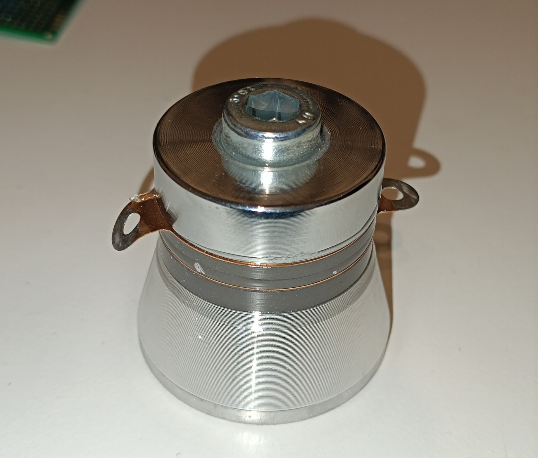
For my printer, I chose 50kHz for driving the piezo, because this frequency is compatible with the 40kHz piezo rings, that you can find in ultrasonic cleaners and because it has a period of 20us which makes calculations with it easier than using an odd number.
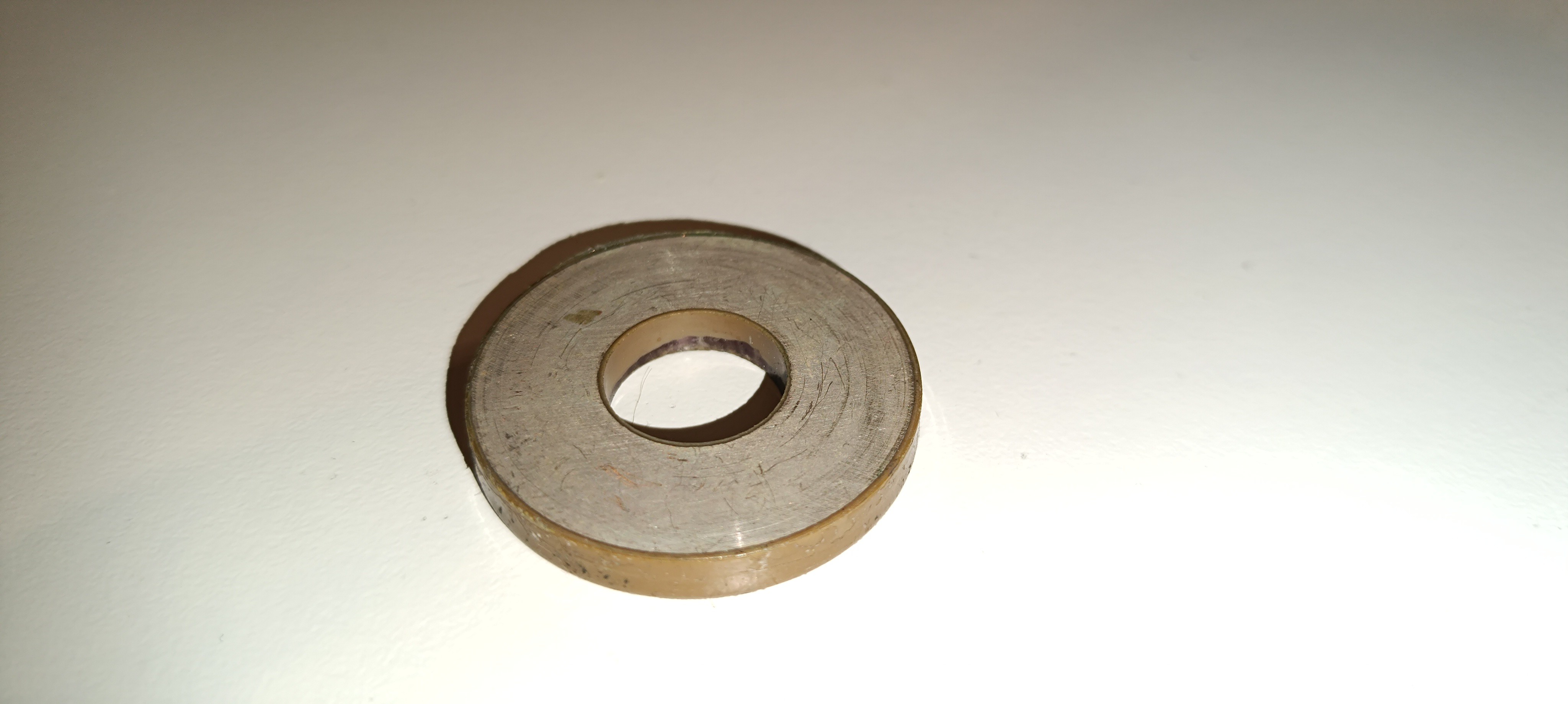
Common 40kHz Ultrasonic Transducer with two Piezo Rings
A single Piezo Ring
Before talking about the phase detection signal's waveform it's worth mentioning, that droplet formation happens over the whole sine wave period while on the other hand, the charging puls can be pretty short, but has to happen at exactly the right moment of the droplet formation process.
The phase detection feature finds the right moment by looking after the phase with the highest charge so that future charging pulses can be executed with this phase setting.
If parameters like ink pressure or viscosity change, the right moment for charging also changes which gets detected by the phase detection feature, which then selects another phase, that fits better to the new parameters.
Phase Detection Signal Waveform
Given that the piezo frequency is 50kHz with a period of 20us and the goal is to design a phase detection signal that completes a complete 360⁰ phase shift in 16 pulses I used a period of 21.25us for these pulses.
My assumption was:
20us / 16 = 1.25us
21.25us * 16 = 340us
20us * 17 = 340us
So, 16 pulse periods take as long as 17 sine wave periods which means that every pulse starts 1.25us later in the sine wave than the one before. The phase detection signal and the sine wave have to start at the same time and after 17 sine wave cycles / 16 pulse cycles, both waves are in sync again.
For the pulse, I just used a 50% duty cycle square wave, but I could just change the duty cycle if it turns out that another duty cycle would be better, just the period has to stay the same, so that 360⁰ phase shift takes 16 pulse cycles.
I added a 340us pause after the phase detection signal so that the period of the whole signal is 680us (340us signal, 340us pause) which equals a frequency of around 1.47kHz.
Piezo Signal in yellow, Phase Detection Signal in green
An older Picture of both WavesHere you can see a Measurement of the Phase Detection Signal
With that, the signal design was completed.
The next task was generating the signal which I will tell you more about in the next log.
In many CIJ printer manuals and papers about CIJ printing it is described that CIJ printers use a closed loop system to monitor droplet breakup. It works by charging some of the droplets with a test signal, measuring the charge of these droplets and analyzing which one got the best charge from the test signal to choose the right timing for droplet charging.
Until lately, I often read that, but didn't fully understand how exactly the printers do that.
Great thanks to @Paulo Campos for helping me understand how Phase Detection works.
Here is my description of it:
A CIJ printer works by using a piezo for breaking up an ink stream into equal-sized droplets. These droplets get charged to a certain voltage level when they fly through a charge electrode and get deflected out of the stream's flight path according to their charge when they pass by a high voltage deflection plate. According to their deflection angle they hit the surface at a lower or higher position of the vertical line that the printhead can reach from it's position.
For droplet charging the right timing is crucial. The charging pulse needs to take place at a certain moment in the droplet formation process.
That's where phase detection comes into play:
The droplet formation process is based on the piezo's vibration which is based on the piezo's drive signal which is a high frequency sine wave. That means that different stages of drop formation occur at different phase angles of the sine wave. To find out at which phase angle of the sine wave the droplets receive the most charge, a phase detection test is used.
The phase detection test signal is applied to the charge electrode whenever the charge electrode is not used for the charging of droplets that are meant for printing.
The phase testing signal is a burst of 16 pulses that cover 0 to 360 degrees in 22,5-degree steps of the piezo signal's sine wave so that each pulse starts at another phase of the sine wave.
This is done to charge 16 successive droplets with different timings/phase settings which will later be read by a phase detection circuit and the printer controller which then can select the best timing/phase setting to get the best possible droplet charging.
In contrast to print charging, test charging usually uses a low negative voltage instead of a high positive voltage to make sure the ink droplets that are used for testing hit the gutter instead of the printing target and to make it easier for the printer controller to differentiate between both types of charge signals.
A positive voltage leads to negatively charged droplets and a negative voltage leads to positively charged droplets. With that, the printer controller sees the positively charged phase detection droplets as positive spikes and the negatively charged printing droplets as negative spikes and can easily differentiate between them. The duration of the measured spikes is dependent on the time of flight of the ink droplets - It shows how long the ink droplet is present to the sensor.
The signal that gets read from the phase detection sensor usually has the shape of a hedgehog, with the highest charge droplets in the middle and the lowest charge droplets on the outside.
The printer controller then selects the phase setting with the highest charge on its droplet and applies it to the charge pulse when printing.
And that's basically it.
It's worth mentioning, that every changing parameter like ink pressure, viscosity, conductivity, dirt in the nozzle and environmental conditions has more or less effect on breakup or charging, so it's likely that the best phase for charging doesn't stay the same during printing what makes a phase detection function essential for operation.
It's also very useful to have the signal from the charged ink droplets on an oscilloscope screen while adjusting parameters on the printer to see which effect they have on breakup and charging.
To date, I could successfully generate the phase testing signal and just recently I could make some progress on the feedback signal reading.
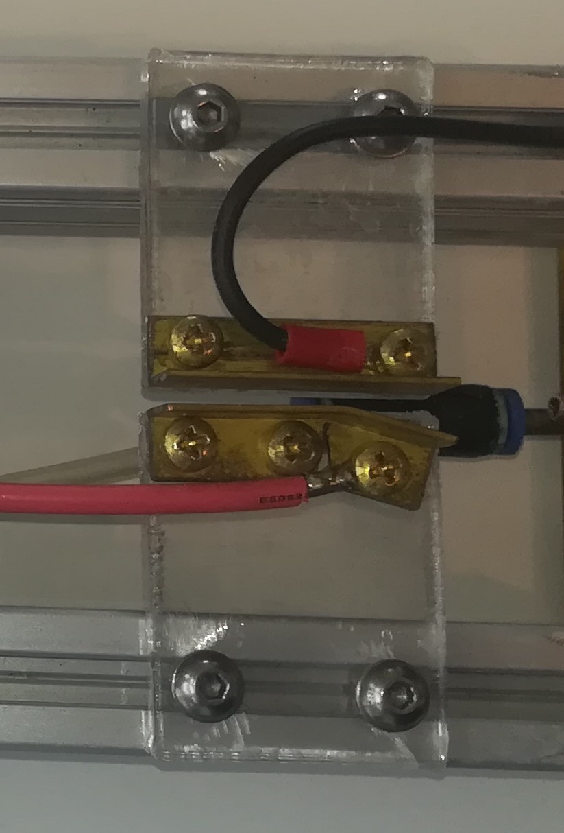
To prove that the 312V charging voltage can be switched, I used an IRFP460 MOSFET for shorting the charge voltage to ground, which turns the charging off.
The charging voltage is already current-limited by a 100k ohm resistor on its output, so shorting it to ground is not a problem.
Now, I can try to apply some signal to the charge electrode and try to measure something on the phase detector next.
While with a single MOSFET, it's only possible to send a square wave to the charge electrode, I will ultimately need a sine wave that has the same frequency as the signal that is sent to the piezo.
Next, I will try to measure a signal with the square wave and if that doesn't work I will try to build a "sine wave driver circuit" and try again.
Update:
I figured out that the phase testing signal is not a sine wave, but a burst of 16 pulses which cover 0 to 360 degree in 22,5 degree steps of the piezo signal's sine wave...
While I spend the last day thinking about the USB charger noise, today I tested out ink stream charging with another voltage source:
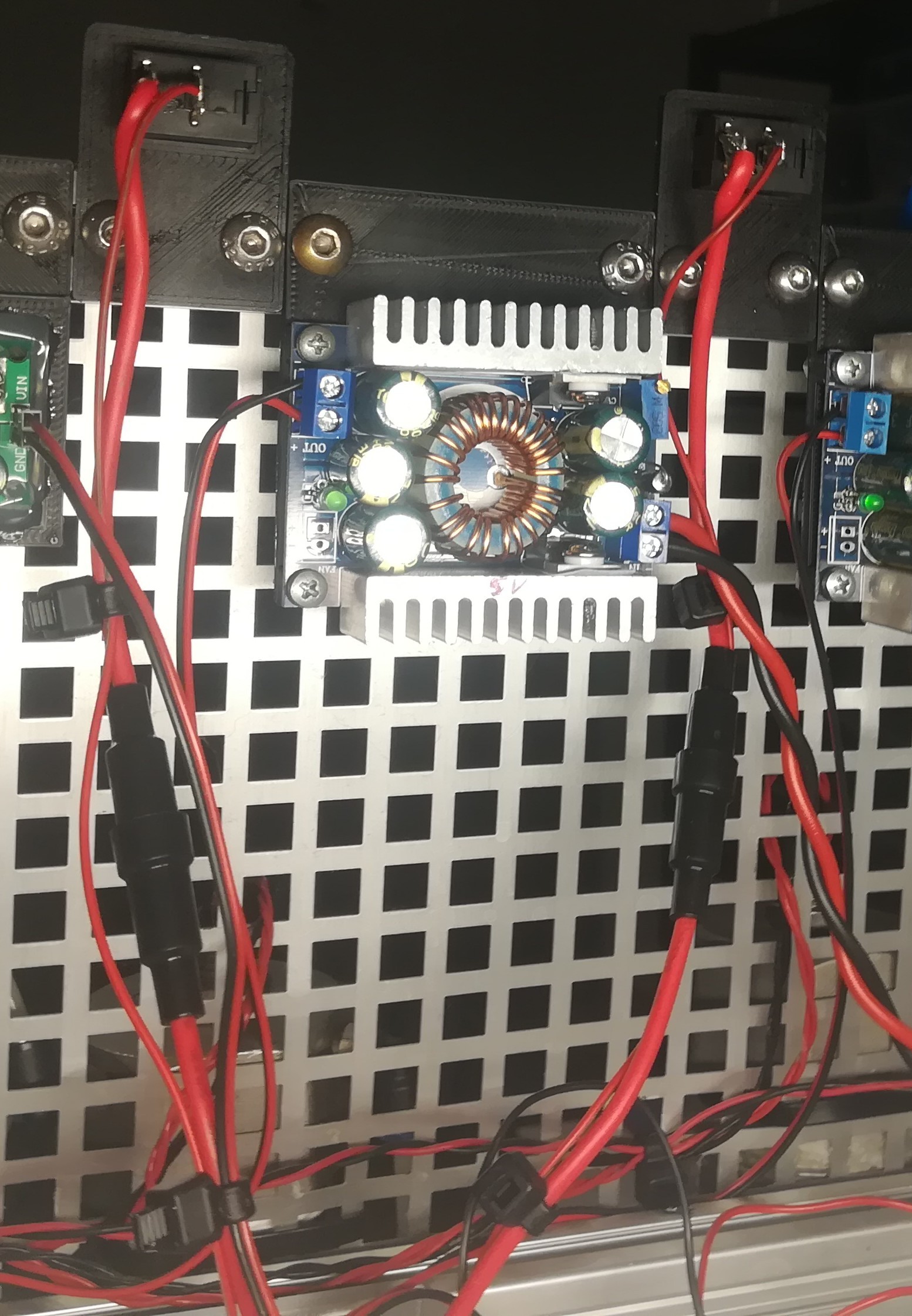
A while ago I added a boost converter to the printer for creating 312V DC.
Boost Converter 12V to 312V
This voltage is already intended to be used as the voltage for ink droplet charging and so I used it for this.
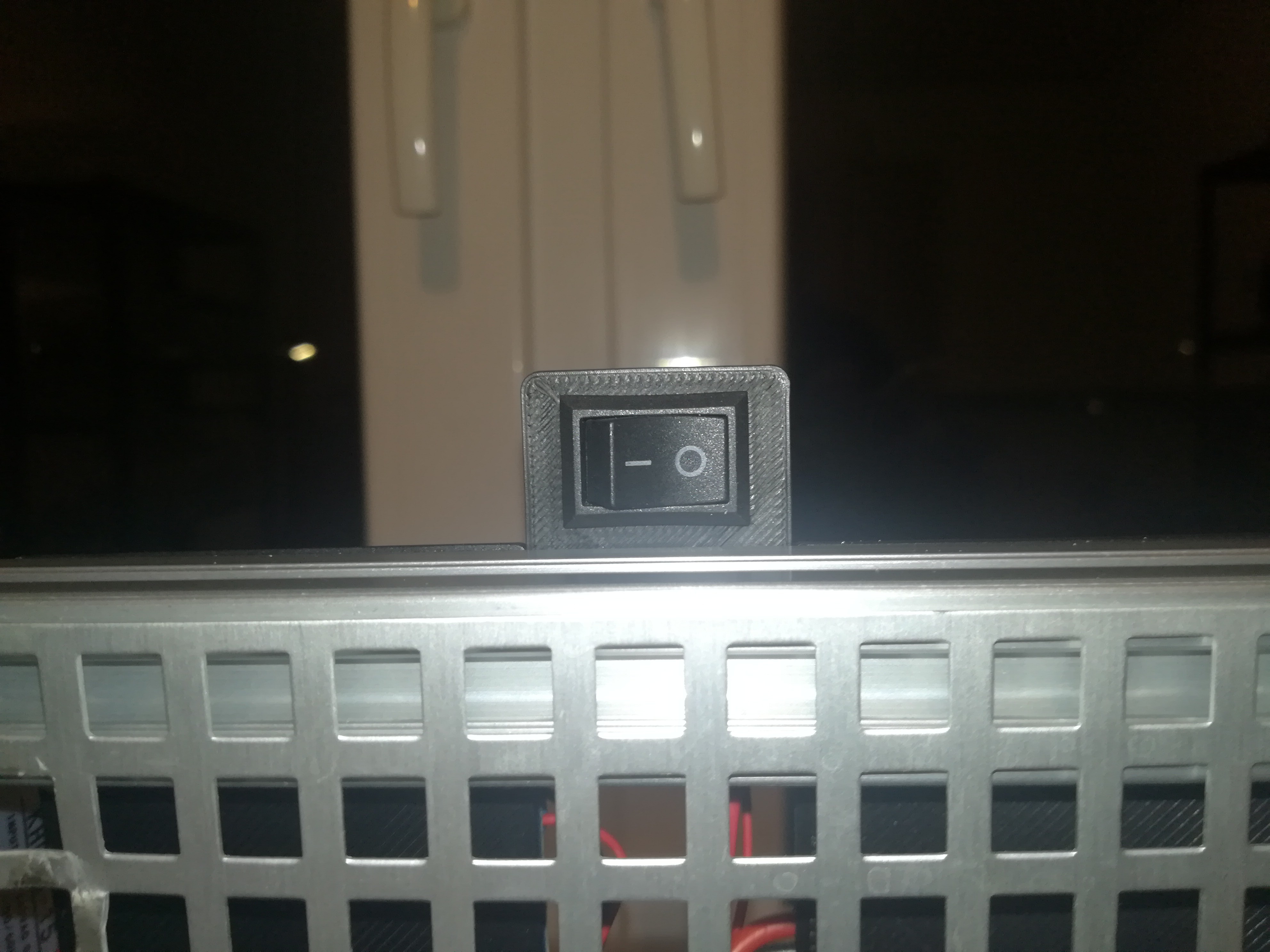
In the video, you can see that by turning on the second switch - the first one from the left is for high voltage and the second one is for the charge voltage - the ink stream gets deflected towards the high voltage plate and by turning off the switch the ink stream returns to its straight alignment.
For this test I set the high voltage to 4.4kV so that the ink stream got more deflected, for not hitting the gutter in its deflected alignment.
This test proves that with the current setup ink stream charging and deflection works.
I think I will contiunue working on the phase detector and on the generation of testing signals next. For ultimately deflecting single droplets out of the ink stream.
I noticed something really interesting when I connected a cheap function generator to the charge electrode without connecting the ground (of the charge electrode).
By doing so I get a pretty high AC voltage reading on the charge electrode. The voltage is also not just a misreading, but actually present. I know that because it can influence the deflection of the ink stream when I turn on the high-voltage deflection plate. Turning the high voltage on while the unknown signal is present leads to an oscillating ink stream - the ink stream moves back and forth from the middle position at around 50Hz.
The function generator is powered by a common 5V USB smartphone charger.
While trying out a different USB charger the signal changed and by running the function generator from a power bank or my notebook the signal disappeared completely.
So, because of the 50Hz and because of the absence of the signal when the function generator is battery powered, I guess that the unknown signal is AC noise from mains that could somehow pass the USB charger and function generator to reach the charge electrode and also charge the ink stream.
I have to admit that I'm pretty happy about this noise because it is helpful to prove some things:
- It shows that the charging and deflection work in general with my current setup.
- It is reproducible. I had unwanted deflection before which was unfortunately not reproducible and so I couldn't dig deeper into it.
- It shows that AC charging leads to deflection in both directions, left and right from the middle position. This means it can charge the ink stream positive and negative. Before, when the high voltage cable was too close to the not connected charging cable, deflection happened only towards the high voltage plate which I think means only negative charging of the droplets caused by a positive voltage on the charge electrode. With the AC noise, it happens in both directions, tho.
- It visually confirms that there is no high voltage to ground leak, which had been a huge problem in the past.
While I was thinking about the source of the signal I decided to do a test to find out whether it comes from the printer, the function generator, the charger, or mains.
For that, I cut off the micro USB plug of an old USB cable to access the +5V and GND USB charger connections.
I then tried to prove my assumption by connecting the +5V USB Charger connection to the oscilloscope and the GND pin of the oscilloscope to mains PE.
By doing so, I could successfully prove that the noise came from the USB charger or mains, but not from the printer or function generator.
To be safe I also tried powering the oscilloscope via battery and could still measure the signal.
Oscilloscope connected to USB Charger + and mains PE
While I still don't know how exactly the signal gets generated - what I guess also doesn't really matter for the project - I think it's a pretty nice coincidence that I didn't connect the function generator's ground to the printer's ground and so could find this noise signal that was very useful for testing.
I just saw that I had even more luck because the other USB charger that I used for comparison creates much less noise and so it likely would have not caused any visible deflection of the ink stream so that the noise would have been overlooked.
Less Noise with a different USB Charger
I did the measurement without connecting the GND of the USB charger to anything and left it floating.
When I then connected the charger's GND to PE, the noise disappeared - it also worked when I swapped the charger's output lines.
My uneducated guess would be, that the noise is created by the switching of the USB charger which couples into the charger's output lines as well as in the mains' live and neutral. Because at some point in the building's electrical system, the neutral line is connected to earth the noise is also present on the PE line.
When now the charger's output, which is not connected to the oscilloscope, gets connected to PE where the oscilloscope's ground pin is also connected to, the oscilloscope receives the 5V DC from the charger's output which can provide much more current than the noise signal. With that the noise is no longer detectable.
While using the function generator and connecting the printhead's ground to it's output the noise was likely shorted so that it did no longer traveled across PE, but through the prindhead's ground to function generator's ground connection instead.
I also could be totally wrong with that...
Anyways... next up is creating a signal that can charge the ink stream as the noise does.
Over the last months, I did some testing with different printhead designs, self-mixed inks, and some new parts and features for improving the reliability of the printer, to prevent frustration while testing.
Great thanks again to @Paulo Campos for helping me with that.
There were two main problems I tried to solve with the improvements:
- Clogging of the nozzle
- Electrode output leaking to ground due to ink/dirt forming a conductive path to ground on the isolators.
Both errors prevent the printer from working, so it's best to prevent them or solve them quickly when they appear.
Maybe I will later add a feature to the printer to detect (and maybe even solve) them when they appear while the printer is printing.
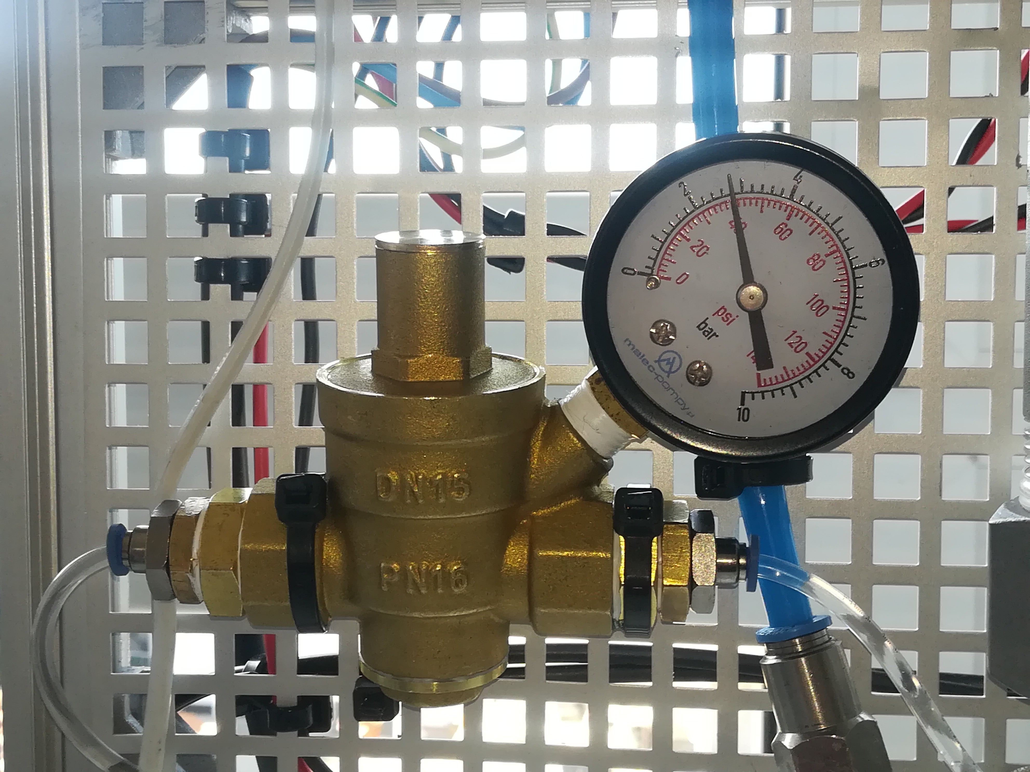
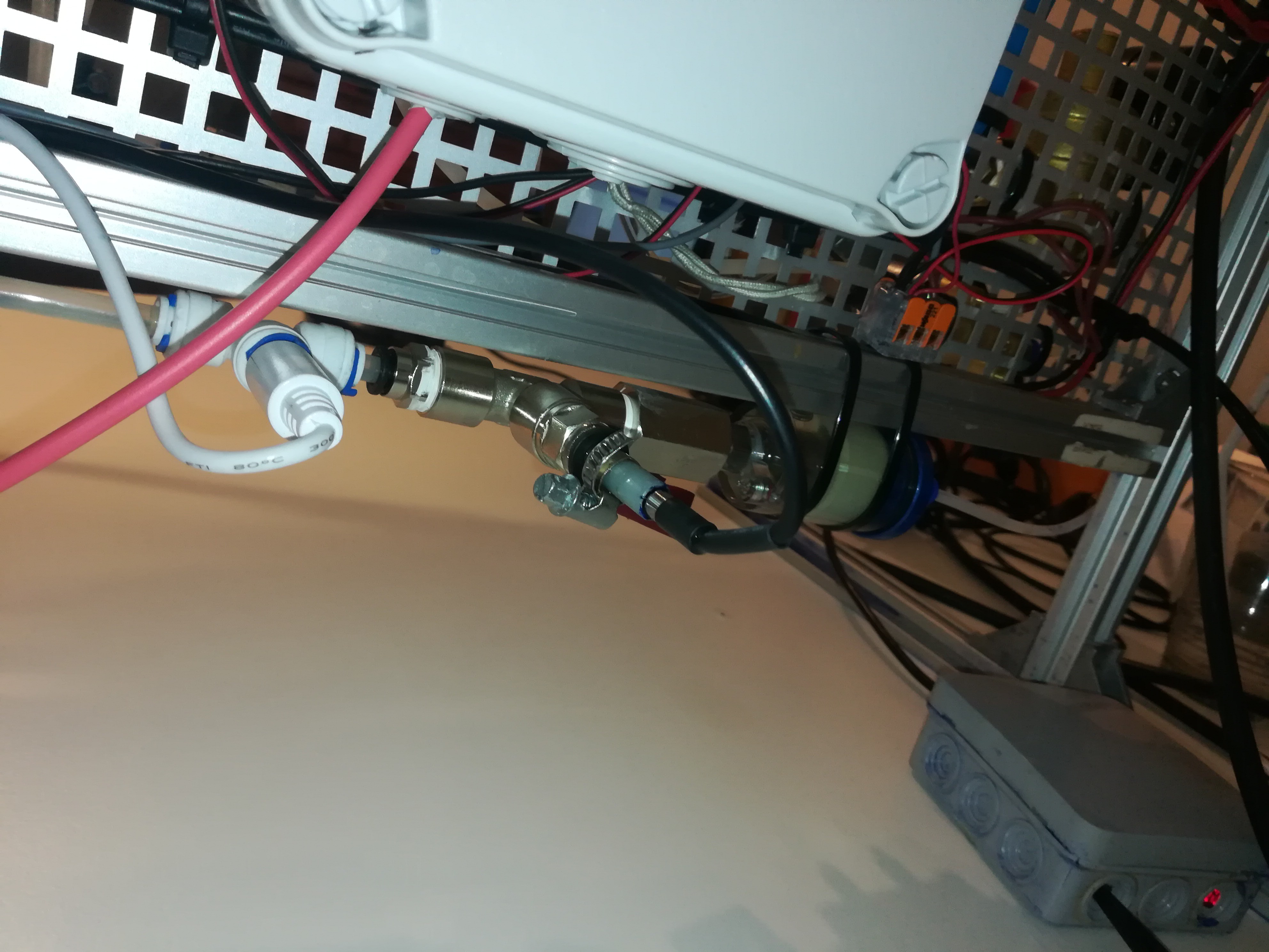
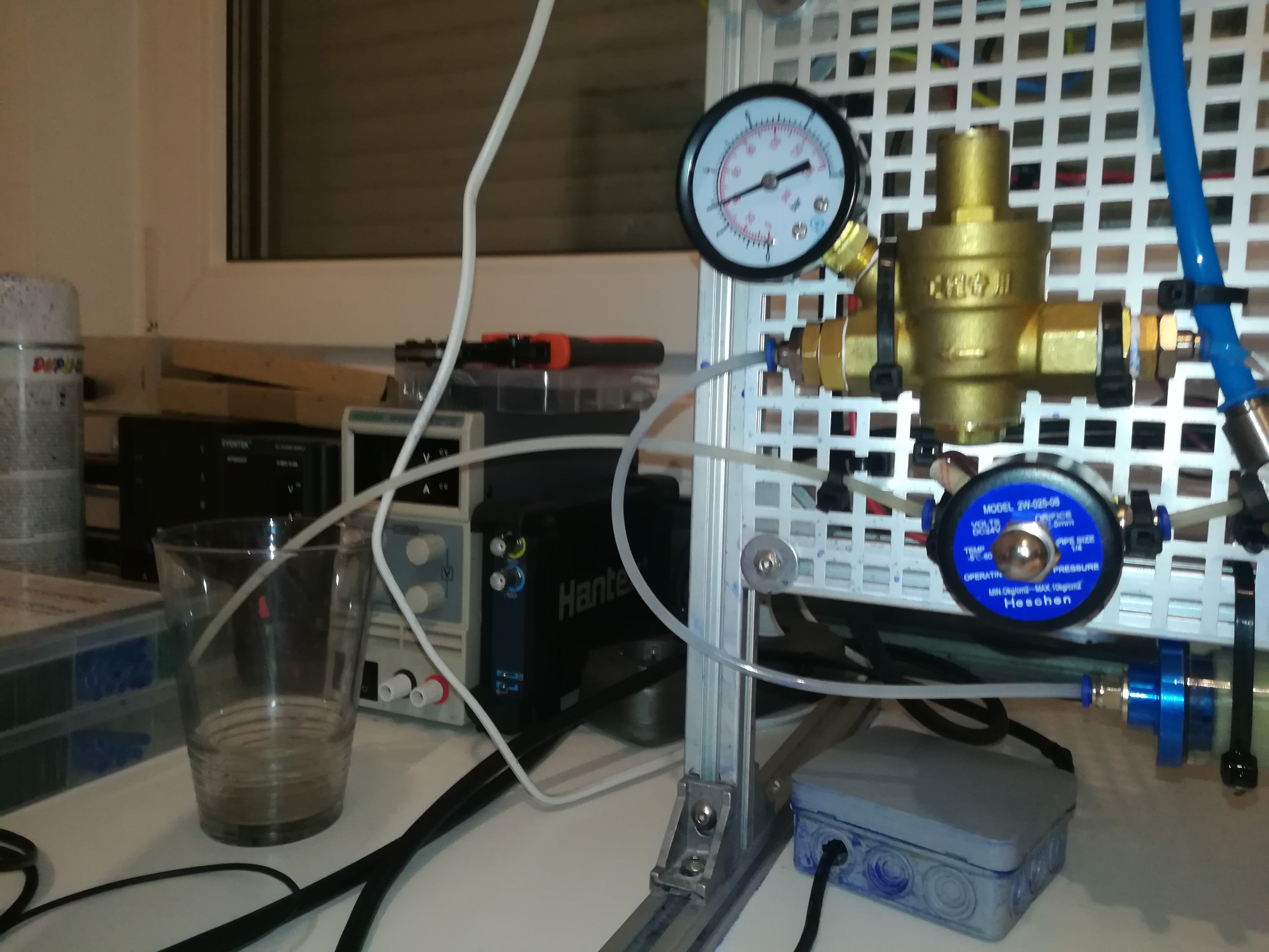
I also improved another problem that caused a rise in ink pressure while reloading the timer chamber by adding a water pressure regulator to the ink line.
This rise led to a shifting of the ink stream break-up point and could shift the break-up point out of the charge electrode which would prevent the printer from working.
Water Pressure Regulator
Adding a water pressure regulator reduced the reloading rise from about 10psi to 1psi which I think should be OK for now.
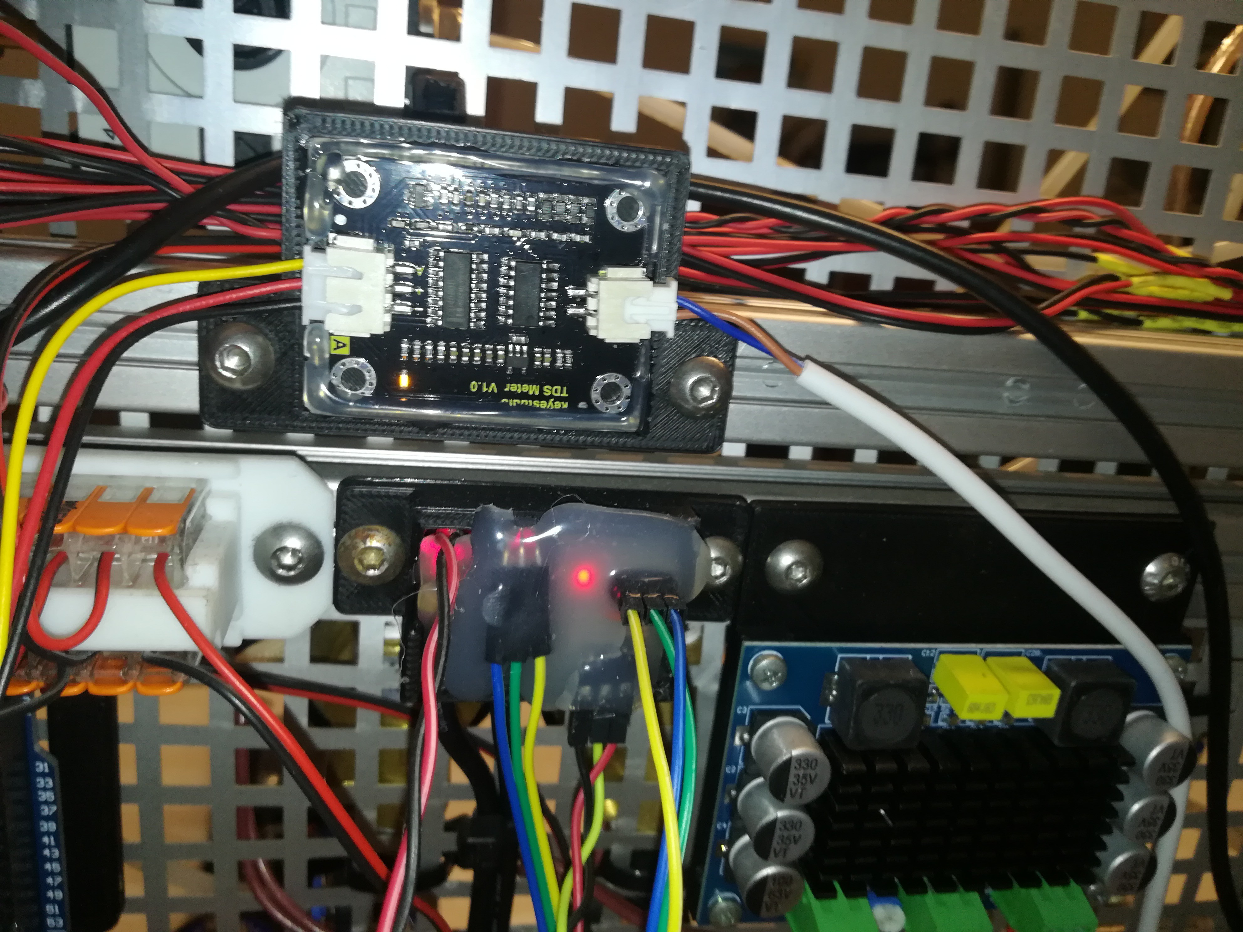
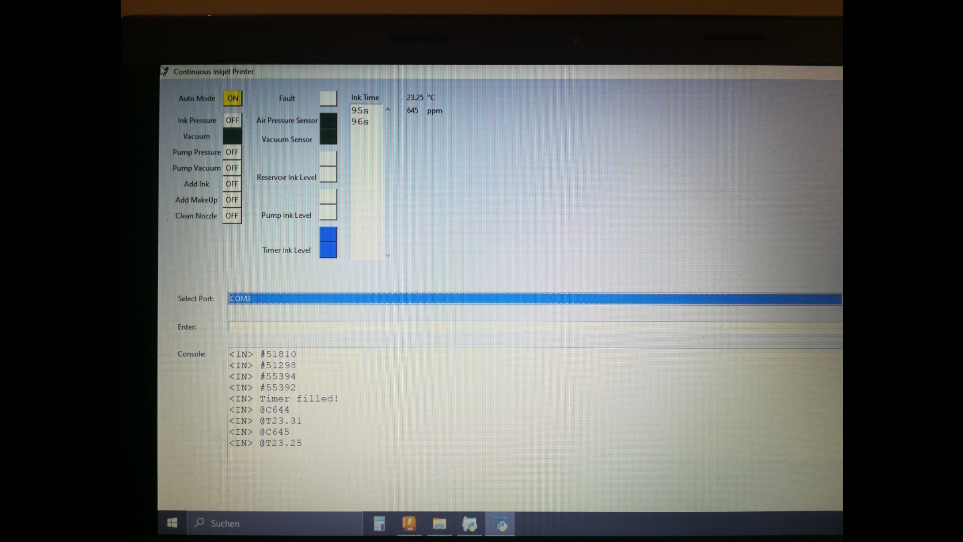
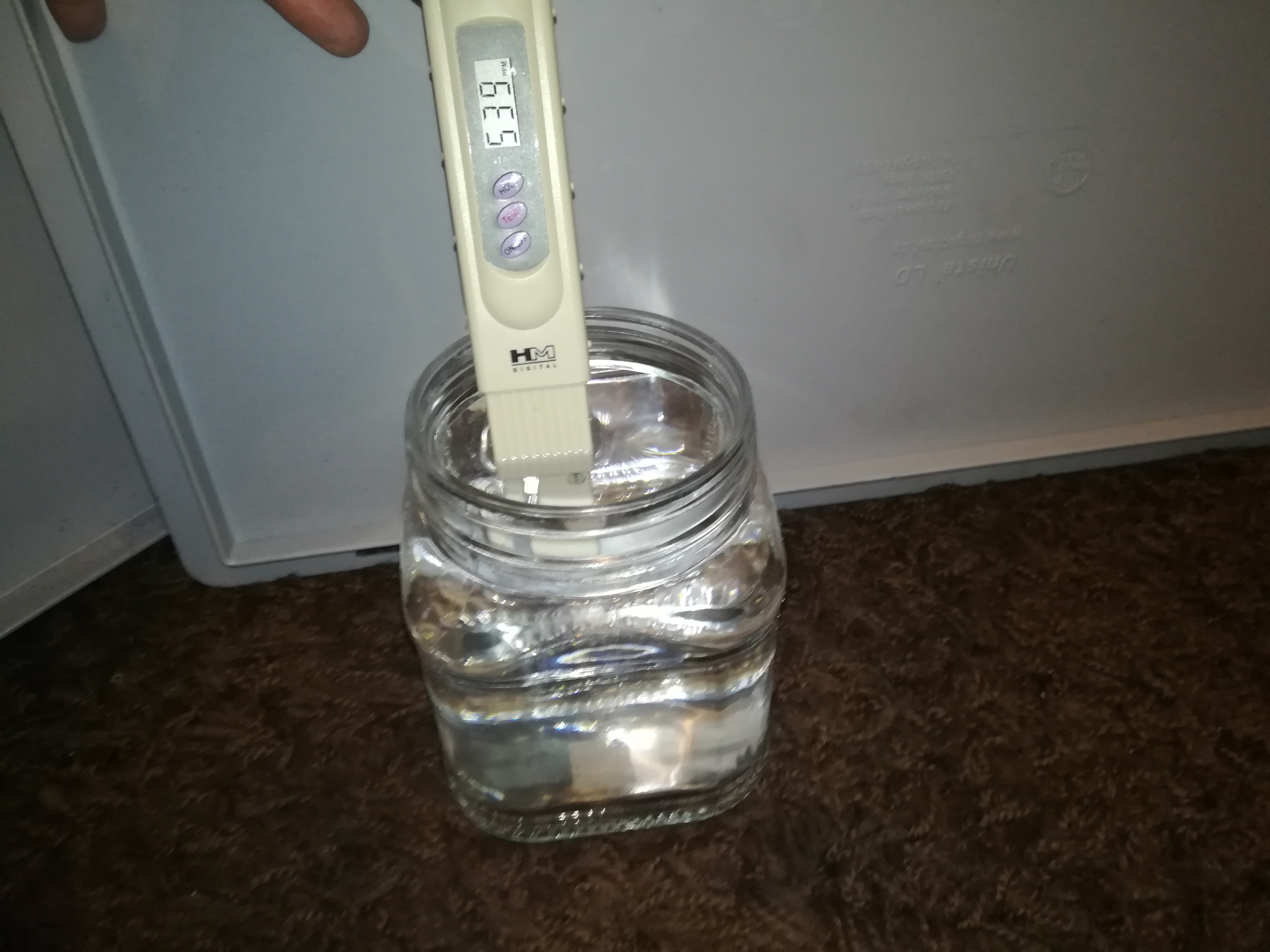
For getting more info about the ink in the system I added a temperature and a TDS sensor to the printer. It's important for the printer's operation to keep the ink at the right conductivity and viscosity.
With the TDS sensor and timer, it's possible to keep an eye on these values.
Ink Filter, Ball Valve, Temperature Sensor, TDS SensorTDS and Temperature SensorTDS Sensor ModuleTemperature and Conductivity on the GUI
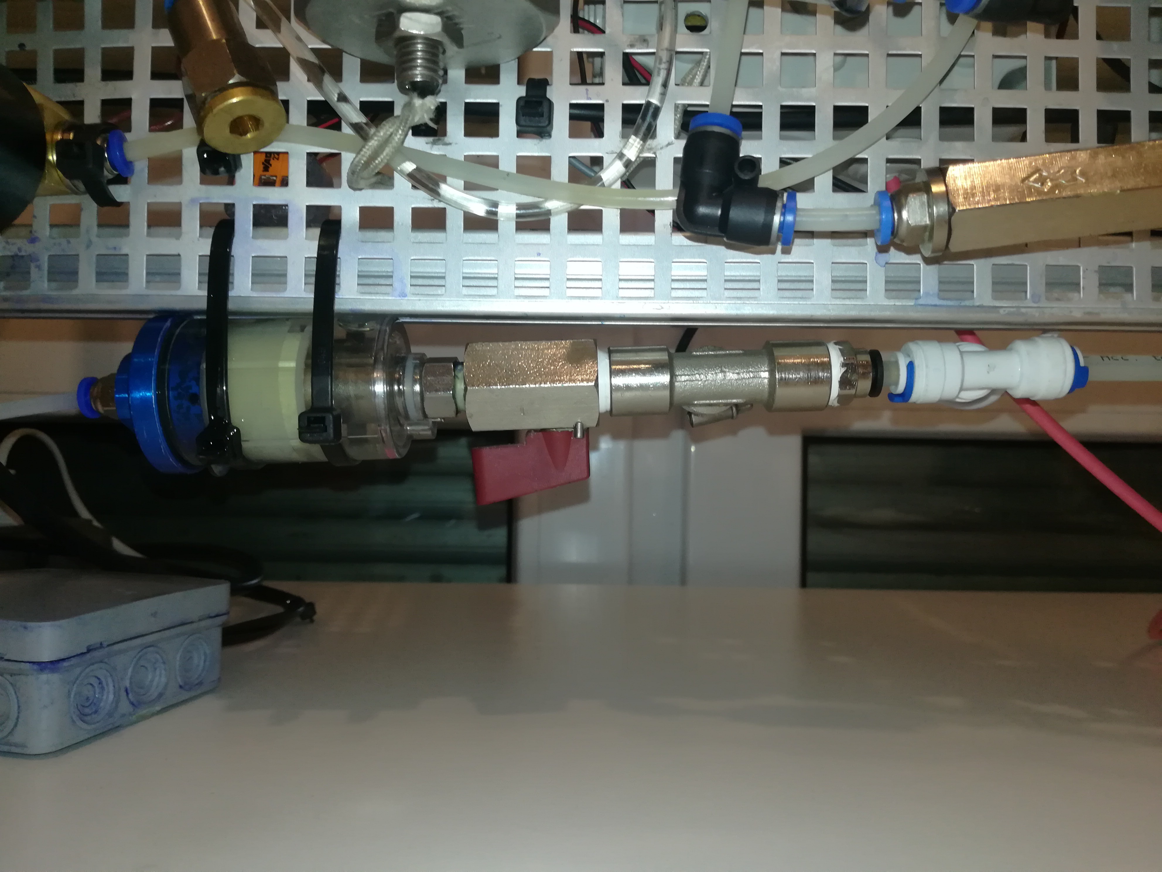
In the future, I want to mount the printhead on a moving carriage for labeling and 3D printing. While the printhead moves and the feed lines bend back and forth the ink pressure would float which could affect the operation and printing quality. To prevent this, I added a small spring-loaded puffer/damper to the ink line that should later act like a capacitor for keeping the ink pressure constant.
Water Impact Damper for preventing Ink Pressure Spikes
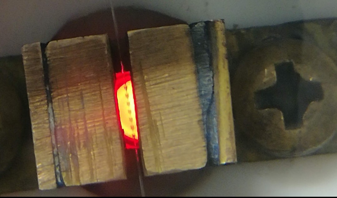
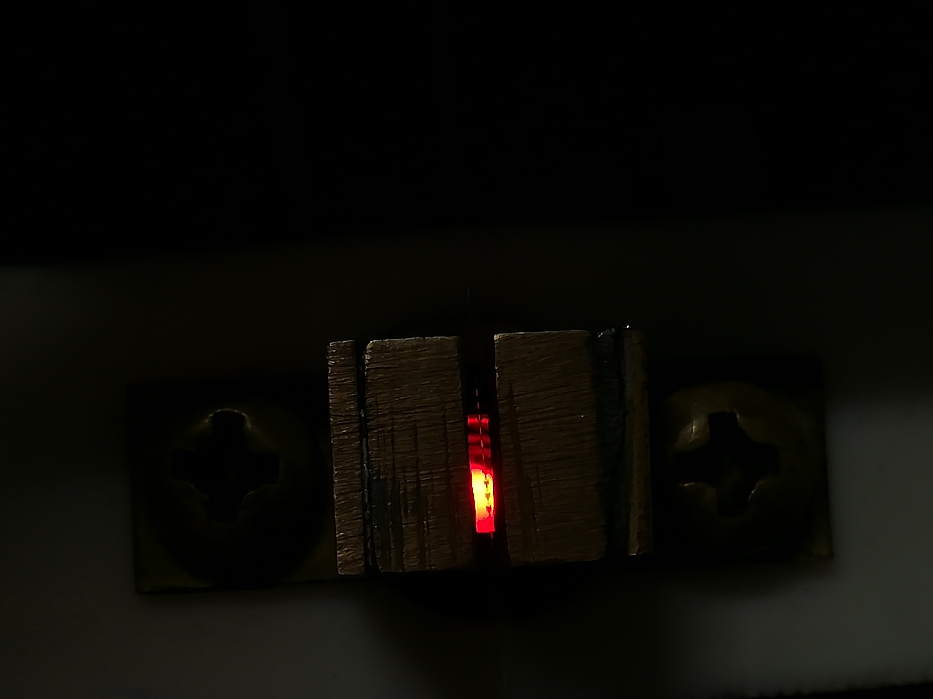
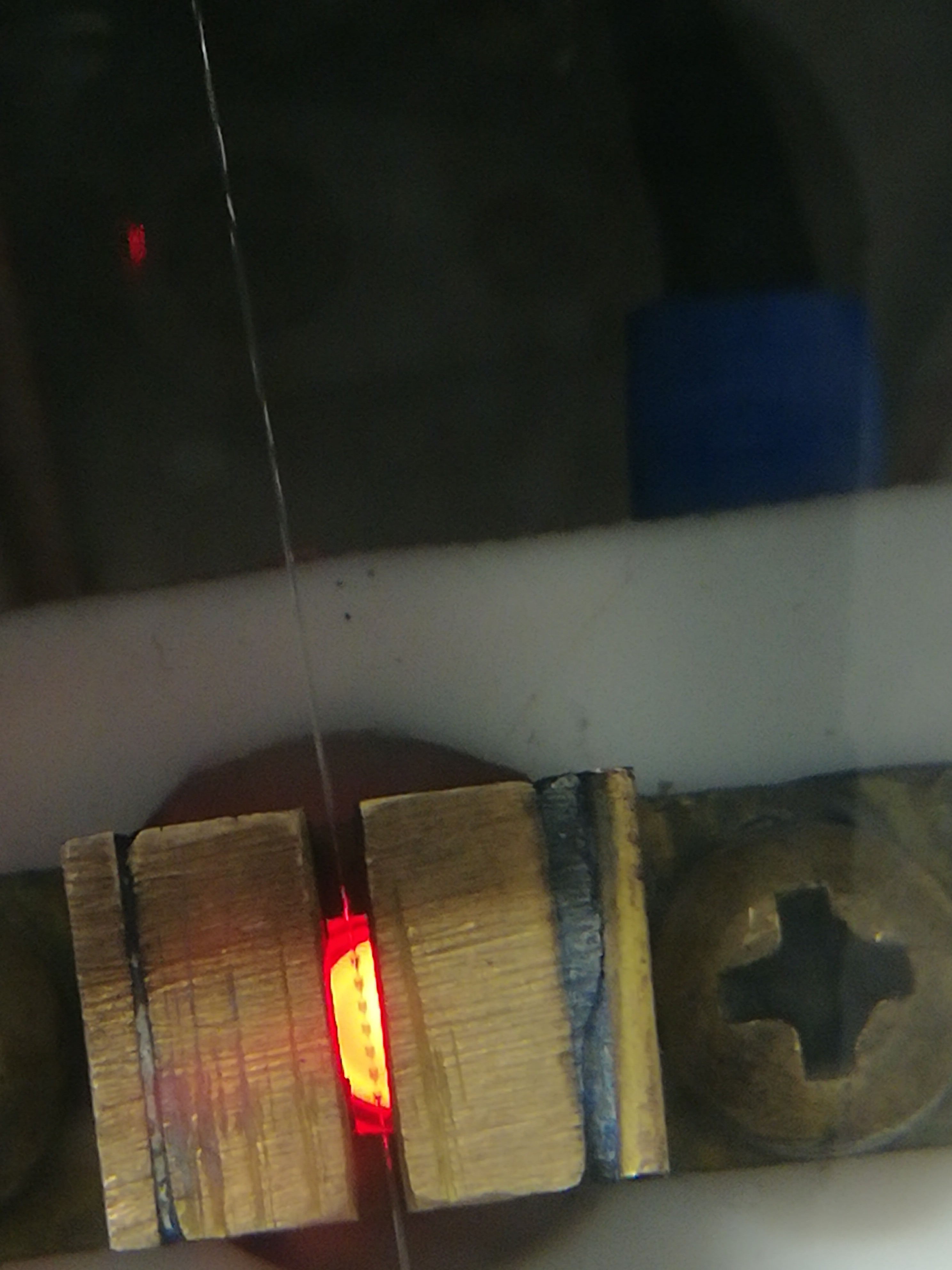
To make the observation of the ink stream break-up and droplet-formation easier, I replaced the white LED with a red LED.
Ink Stream Break-UpInk Droplets under a red LED
The Output to Ground Leakage Problem:
In the past, I did a lot of testing with water-based inks, because water is safe to use and not flammable.
A major drawback of water is that it takes a long time to evaporate.
That leads to a lot of problems with it like:
- Corrosion on places where conductive water reaches in, but does not dry for a really long time like on the aluminum coated piezo ring or underside of aluminum profiles.
- Water puddles from ink stream alignment or dealing with a clogged nozzle. Because the water takes very long to dry, the ink can collect on the printhead, desktop, and floor even if only a small amount of ink misses the gutter or hits an electrode. With water, this leads really quickly to puddles that would otherwise just evaporate after a few seconds.
- Output to ground leakage caused by small amounts of conductive water settle in small scratches from cutting at the edges of the isolators, which renders the electrodes unusable for a long period of time after each splashing with test ink - what happens very often while testing.
This made testing in the past as good as impossible.
In the end, I came to the conclusion that the fire hazard of fast-drying liquids like ethanol is easier to handle with the right safety precautions than the problems caused by slow-drying water.
In the industry, most CIJ printers also use fast-drying ketone or alcohol-based inks.
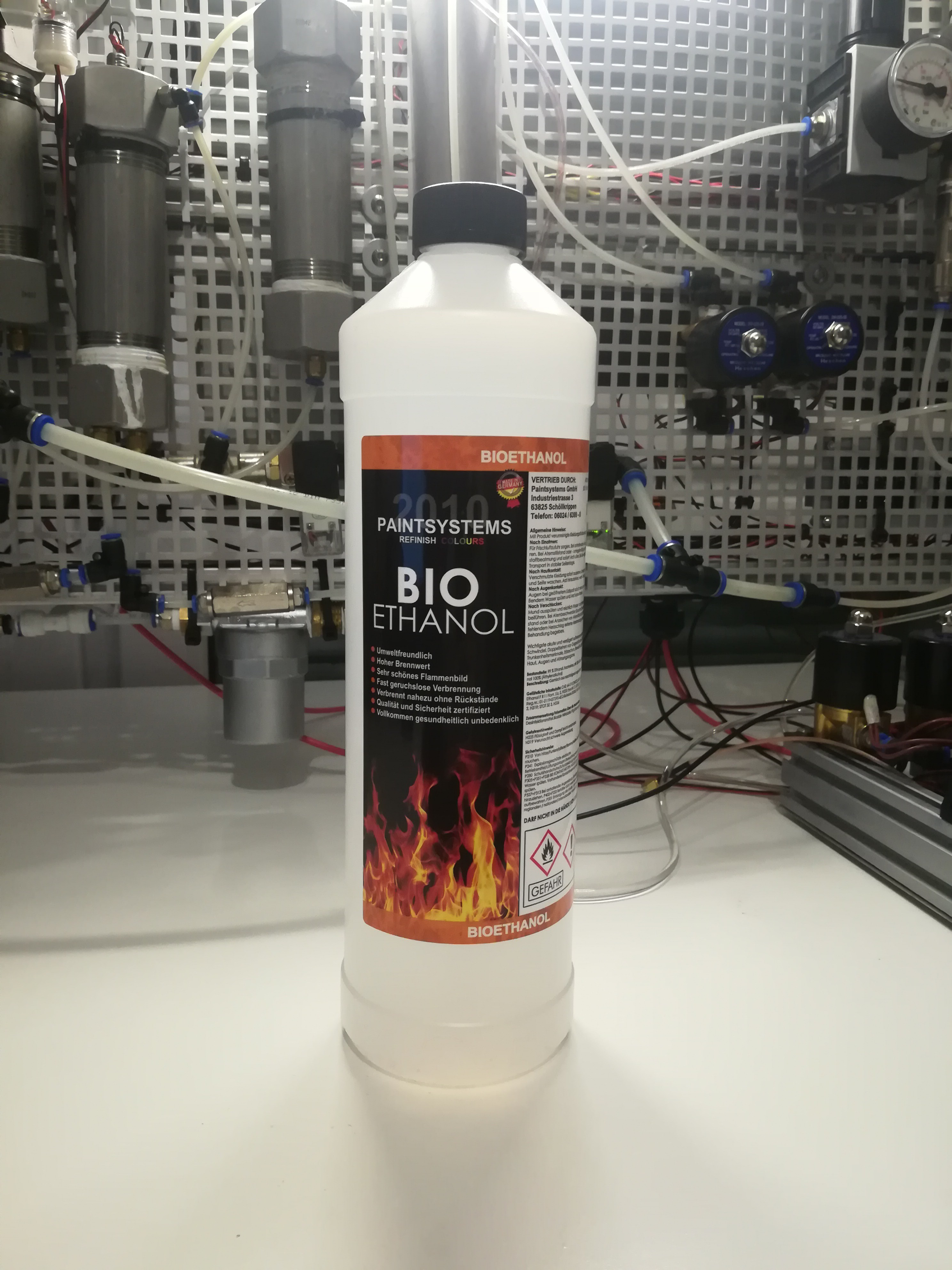
And so I switched to ethanol-based ink.
Bio Ethanol that is normally used for Ethanol Fireplaces
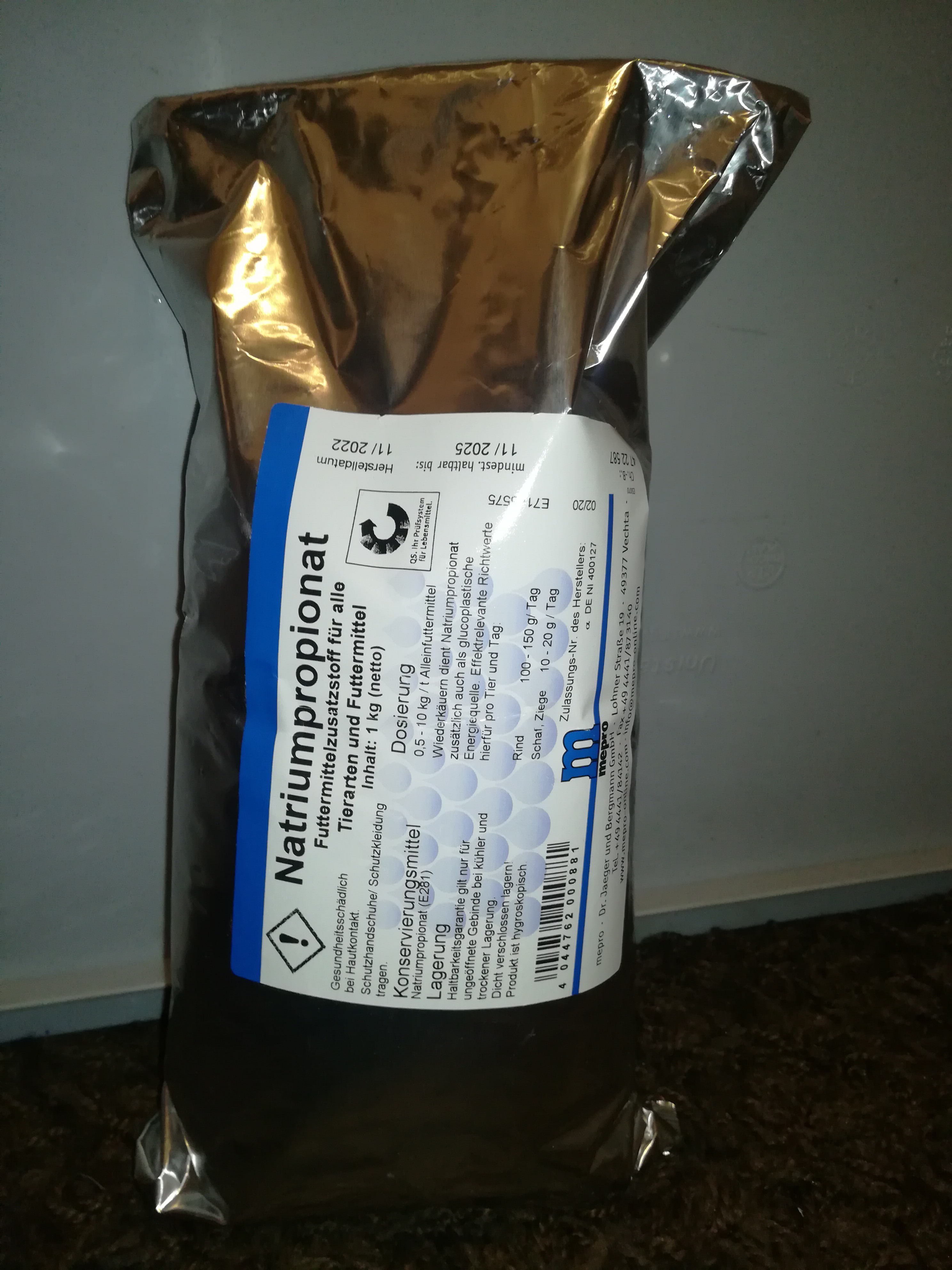
Today, I received a bag of sodium propionate which contrary to sodium chloride and sodium carbonate (which I used before with water) dissolves well enough in ethanol to increase the conductivity to the needed level without the need to add water to the mix.
Sodium Propionate for Farm Animal's Food is also suitable for increasing the conductivity of Ethanol Measuring the Conductivity of Ethanol mixed with Sodium Propionate
With ethanol, the situation really improved. When some ethanol got spilled on the printhead, table, or floor it could be wiped off and the residue on the surface evaporated completely after just a few seconds.
Some parts of the printer like the ink filter, piezo mount, and polystyrene parts were not compatible with ethanol, so I had to replace them.
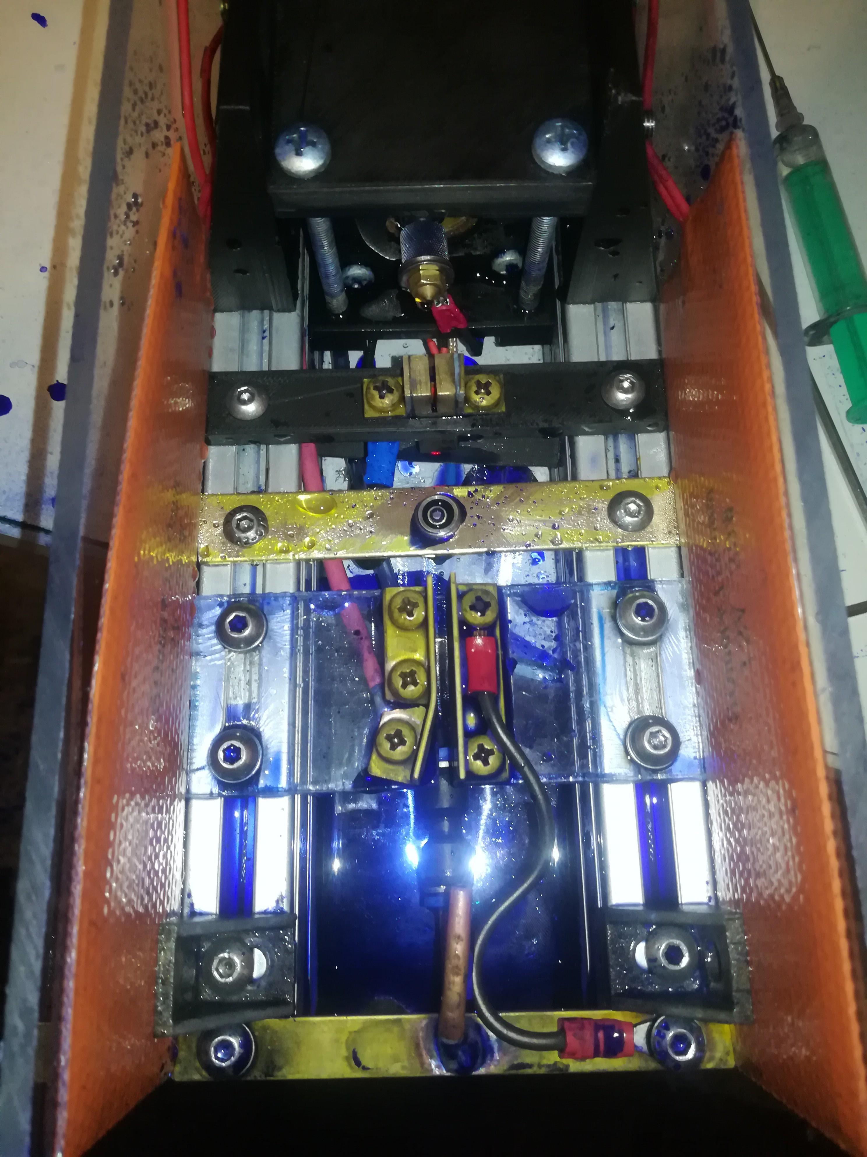
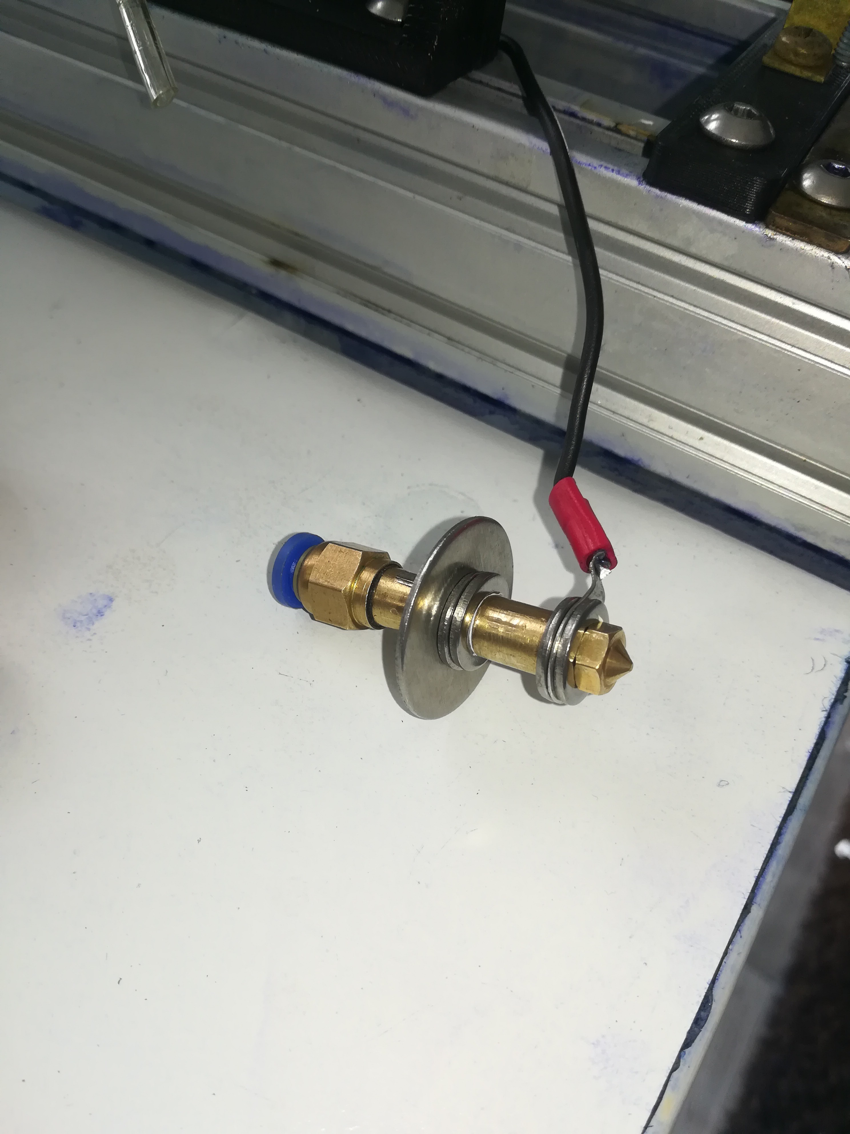
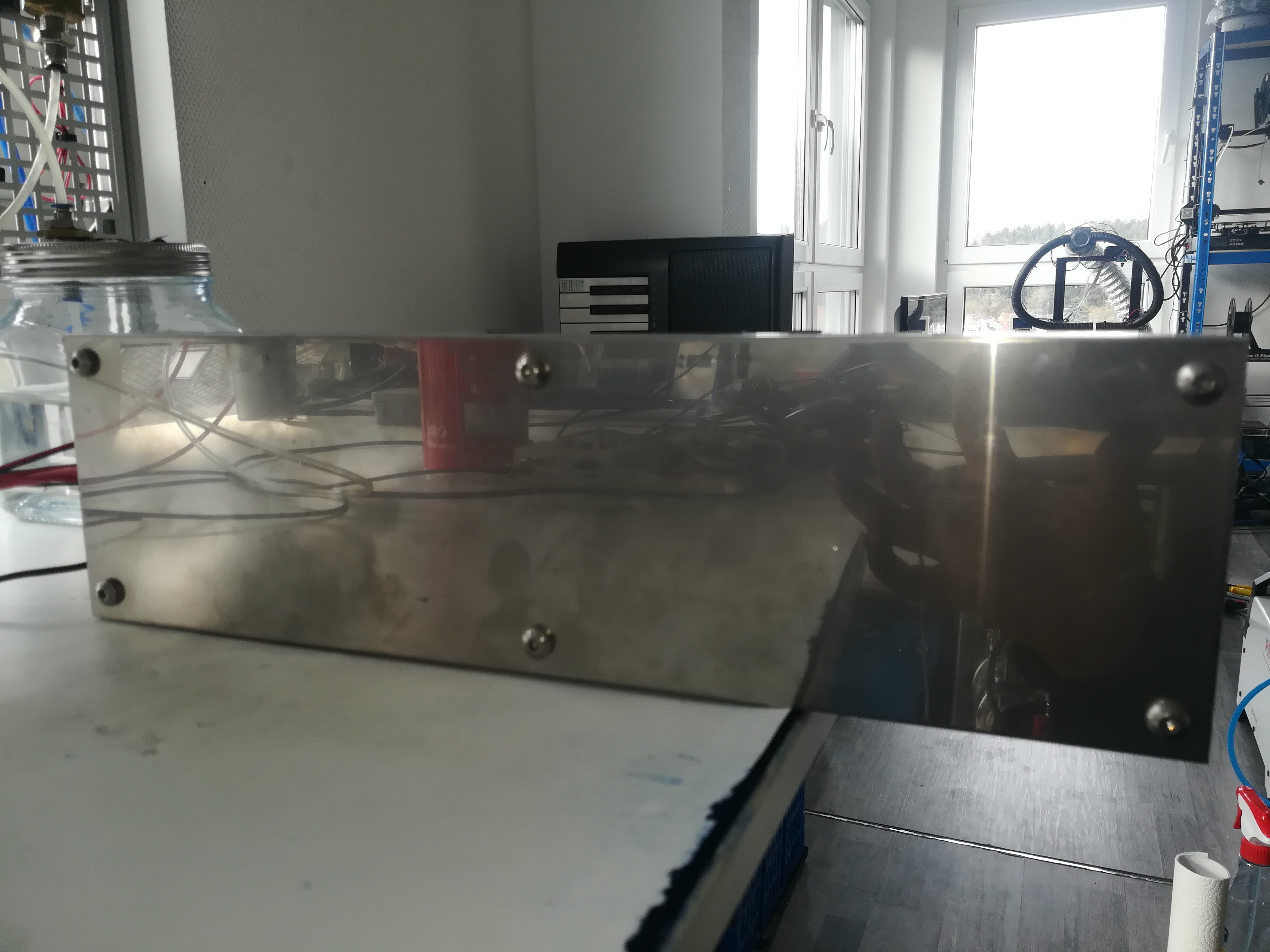
Old Printhead DesignNew Printhead DesignNew Nozzle Assembly (The Stainless Steel Washer got later replaced by PTFE)New Ink FilterNew Stainless Steel Bottom Plate
On the printhead, I tried different materials for the isolators. While using the water ink I used polystyrene isolators and 3D printed isolators, but because the water settled in every small scratch and also soaked between the layers of 3D printed parts it did not work very well - the smooth polystyrene worked better for water than the 3D printed parts.
For ethanol, polystyrene is not suitable because it gets dissolved by it over time. 3D printed parts work better than with water but the ethanol also creeps between the layers and stays there longer.
In the end, I had the idea to use PTFE for the isolators which has a high chemical resistance and also a liquid and dirt-repelling surface which is very nice for keeping the isolators dirt free to prevent forming of conductive paths to ground on the isolator's surface.
Piezo Isolator, Charge Electrode Isolator, and Deflection Plate Isolator made out of PTFE
I did some testing of the high-voltage electrode:
I measured the high voltage which I set to 3,33kV. Then I sprayed the isolator with ethanol which led to the measured voltage dropping to around 100V. Then I wiped the top and bottom of the isolator with a paper towel and blew some air on the isolator to let the residue evaporate. I measured the voltage again and measured 2,95kV which over the next seconds rose back to 3,33kV.
It seems like, from all tested materials PTFE worked the best so far.
I think that the ground leakage problem is solved for now and I can finally start testing with the electrodes. And in case of an isolator gets splashed with ink, the ink will dry off pretty quickly so that the testing can be continued after just a few seconds.
The Nozzle Clogging Problem:
Before the last change nozzle clogging was a serious problem. When some dirt or PTFE flake from sealing PTFE tape reached the nozzle, it obscured the ink stream which prevented drop break-up from happening, changed the break-up point position, or led to a non-straight ink stream that hit an electrode, missed the gutter or shoot across the room.
Sometimes it helped to wipe the nozzle tip with a finger to unclog the nozzle, but often it was needed to disassemble the nozzle assembly and clean or replace the nozzle.
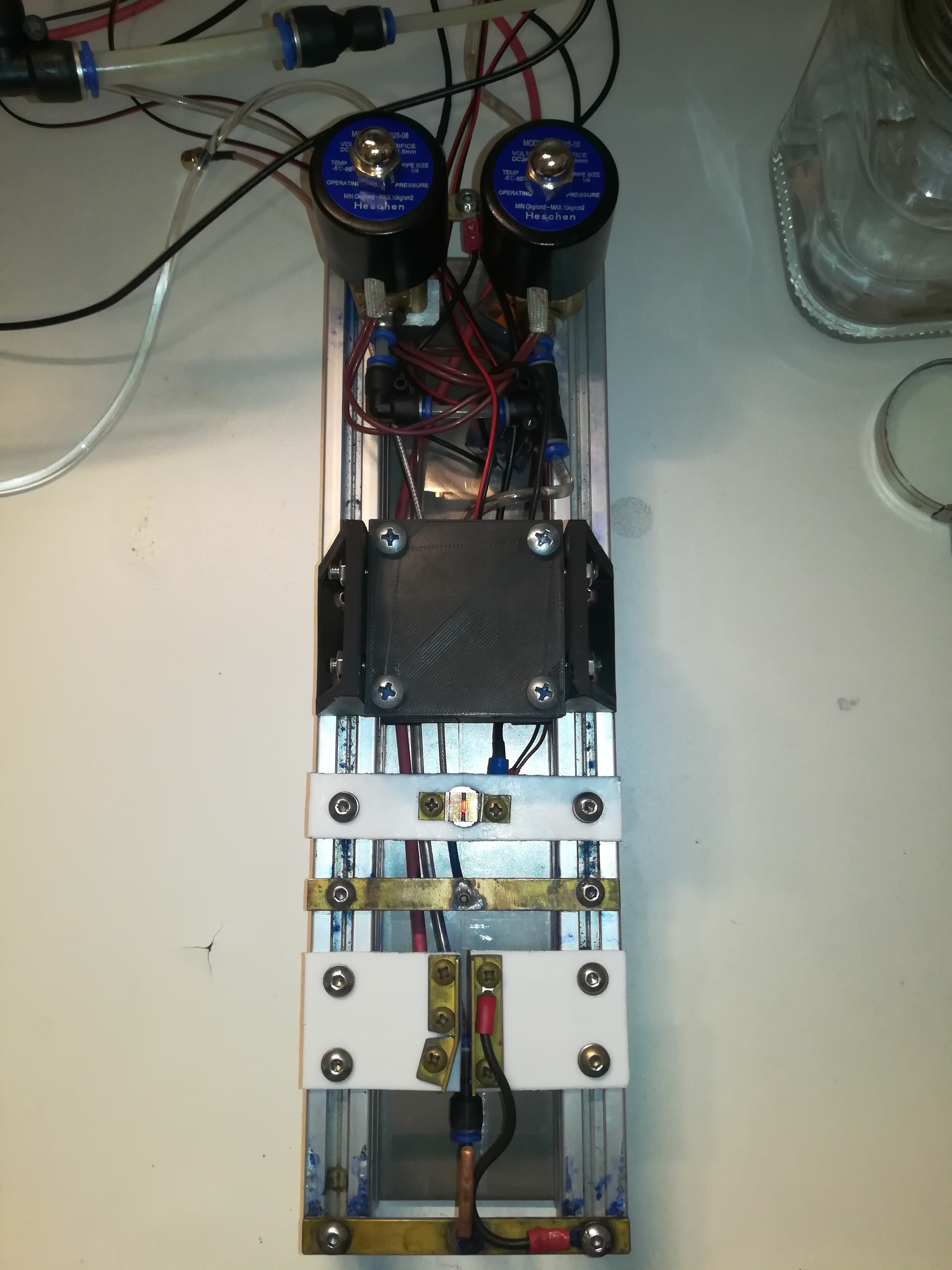
So I added a nozzle cleaning feature to the printer, that connects the nozzle to the primary vacuum line if activated.
This way the nozzle can be flushed and dirt can be disposed of into the vacuum puffer chamber. While doing so any flushing solution can be used because unlike the normal ink, the dirt and flushing solution doesn't get recycled in the system and so they can not contaminate the ink in the system.
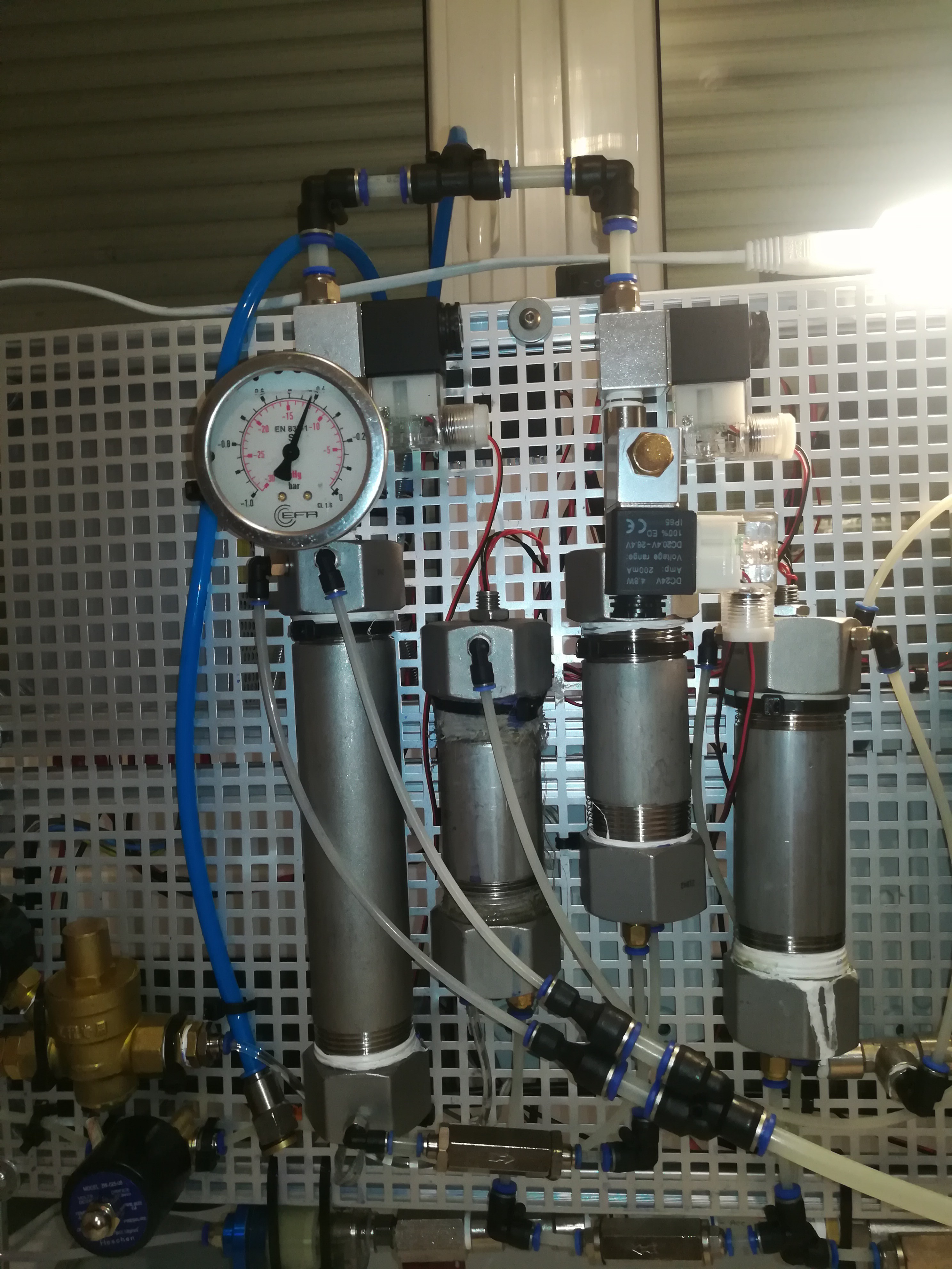
The cleaning function is turned on by the two valves on the back of the printer. The left one is used for the ink and the right one is used for the vacuum.
Printhead with two Valves for the Nozzle Cleaning Function
The "dirty ink" flows from the printhead through the main vacuum line to the vacuum puffer chamber and gets collected there. The vacuum puffer chamber has a float switch to shut the printer down or perform another action when it is full.
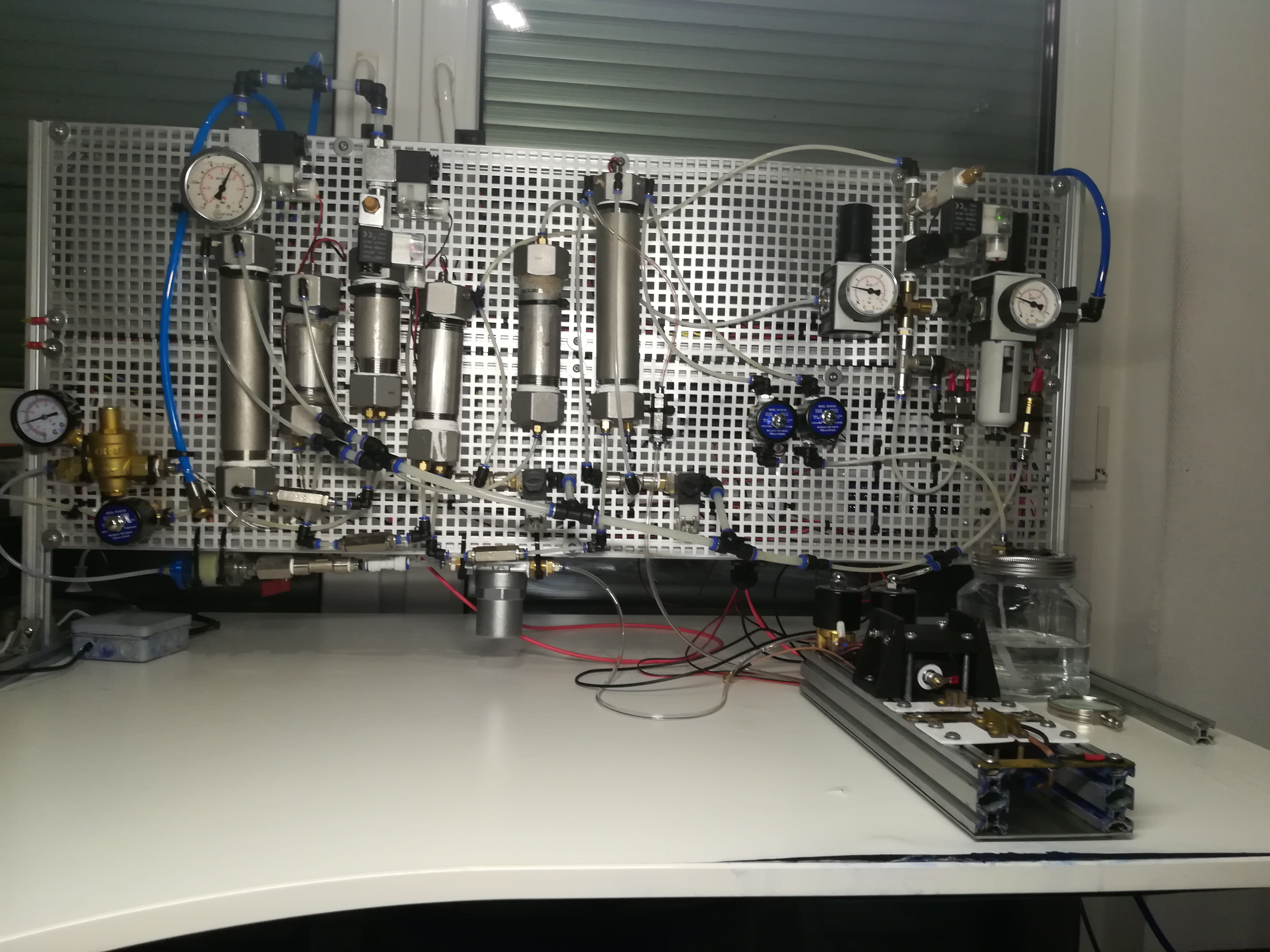
The outer left Chamber with the Vacuum Gauge is the Vacuum Puffer Chamber
For draining the vacuum puffer chamber I added another chamber - a draining chamber to the printer.
The draining chamber has a valve for draining a valve for venting and a valve for vacuum.
For draining the vacuum puffer chamber, the vacuum of it is closed with the valve at the top. At the same time, the venting and drain valve of the draining chamber is closed and the vacuum valve of it is opened. By doing so the "dirty ink" is drawn through a check valve from the vacuum puffer chamber into the draining chamber.
When the vacuum puffer chamber is empty. The valve of it opens again while the vacuum valve of the draining chamber closes and the venting and drain valves of the draining chamber open.
The "dirty ink" that is now in the draining chamber can now exit the printer into a waste container.
With the newly added draining feature, it is possible to drain the vacuum puffer chamber which besides "dirty ink" also catches boiled-off ink and excess ink from the pump and reservoir chamber. The new feature makes it possible to drain the vacuum puffer chamber while the printer is printing. Otherwise, it would be required to shut off the vacuum first to drain the vacuum buffer chamber which would require a shutdown of the printer.
The third Chamber from the left is the Draining ChamberHere you can see the Drain Valve and the Waste Ink Line
I think with the nozzle cleaning feature and draining feature nozzle clogging will be less of a problem.
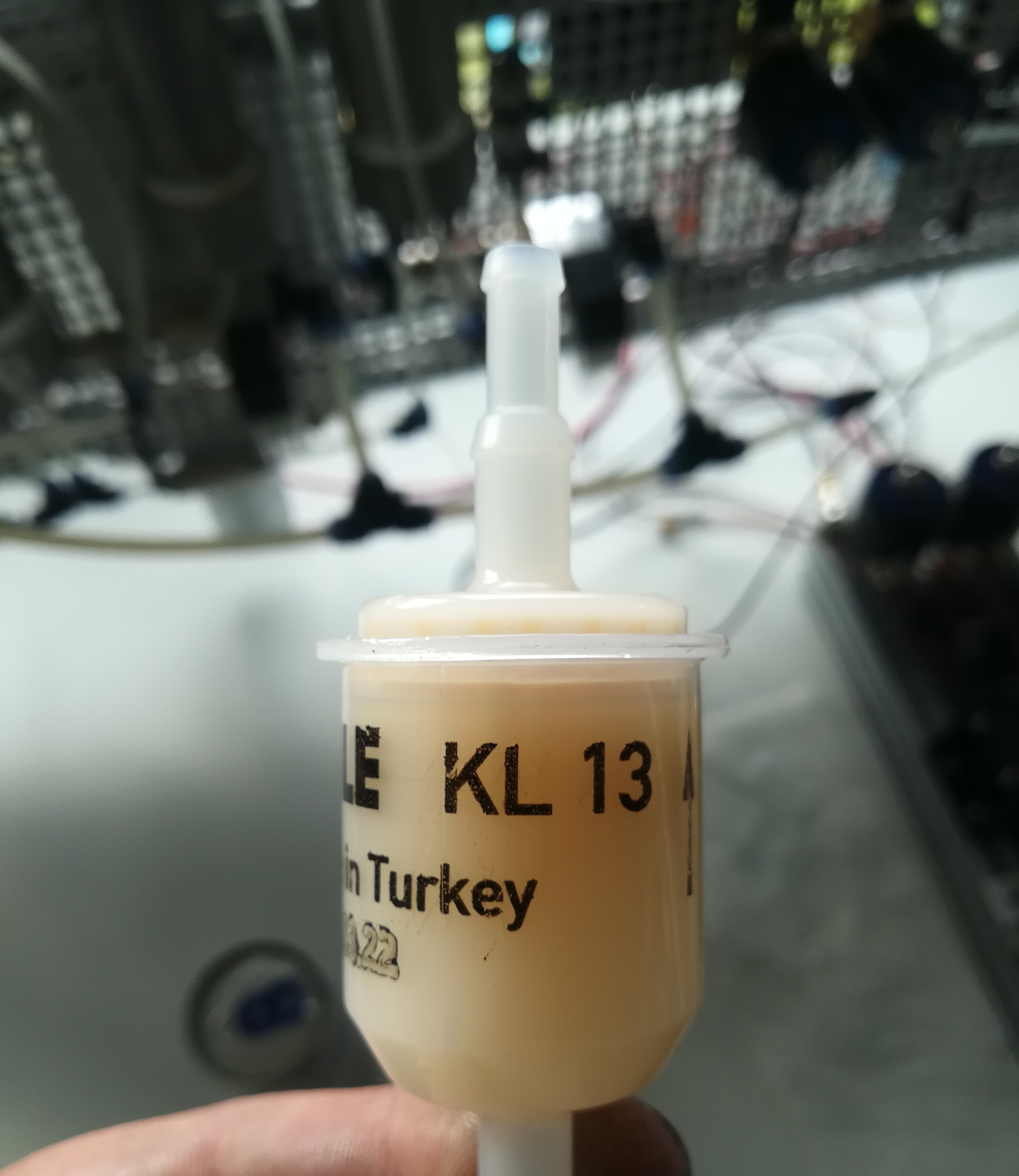
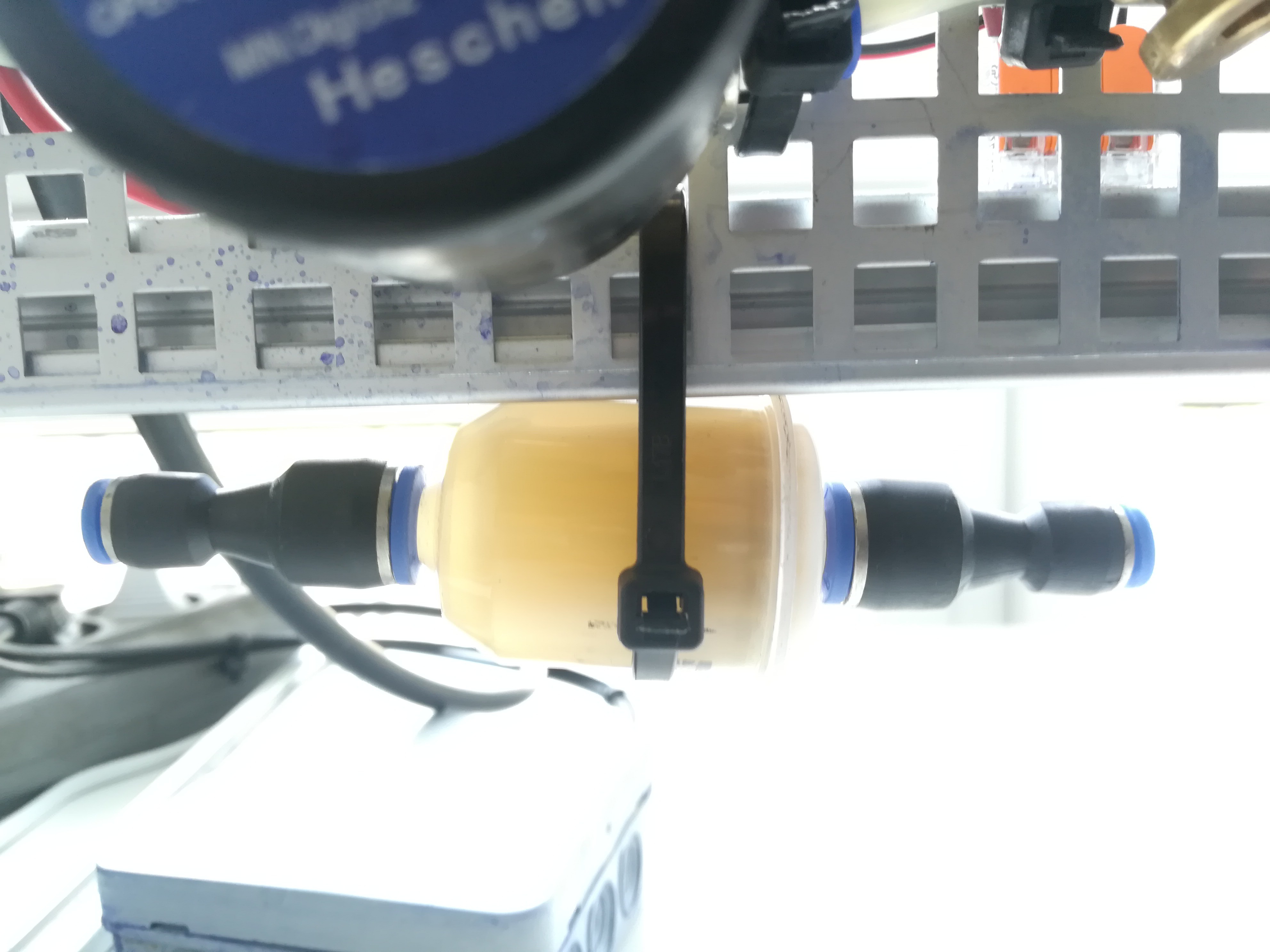
Update:
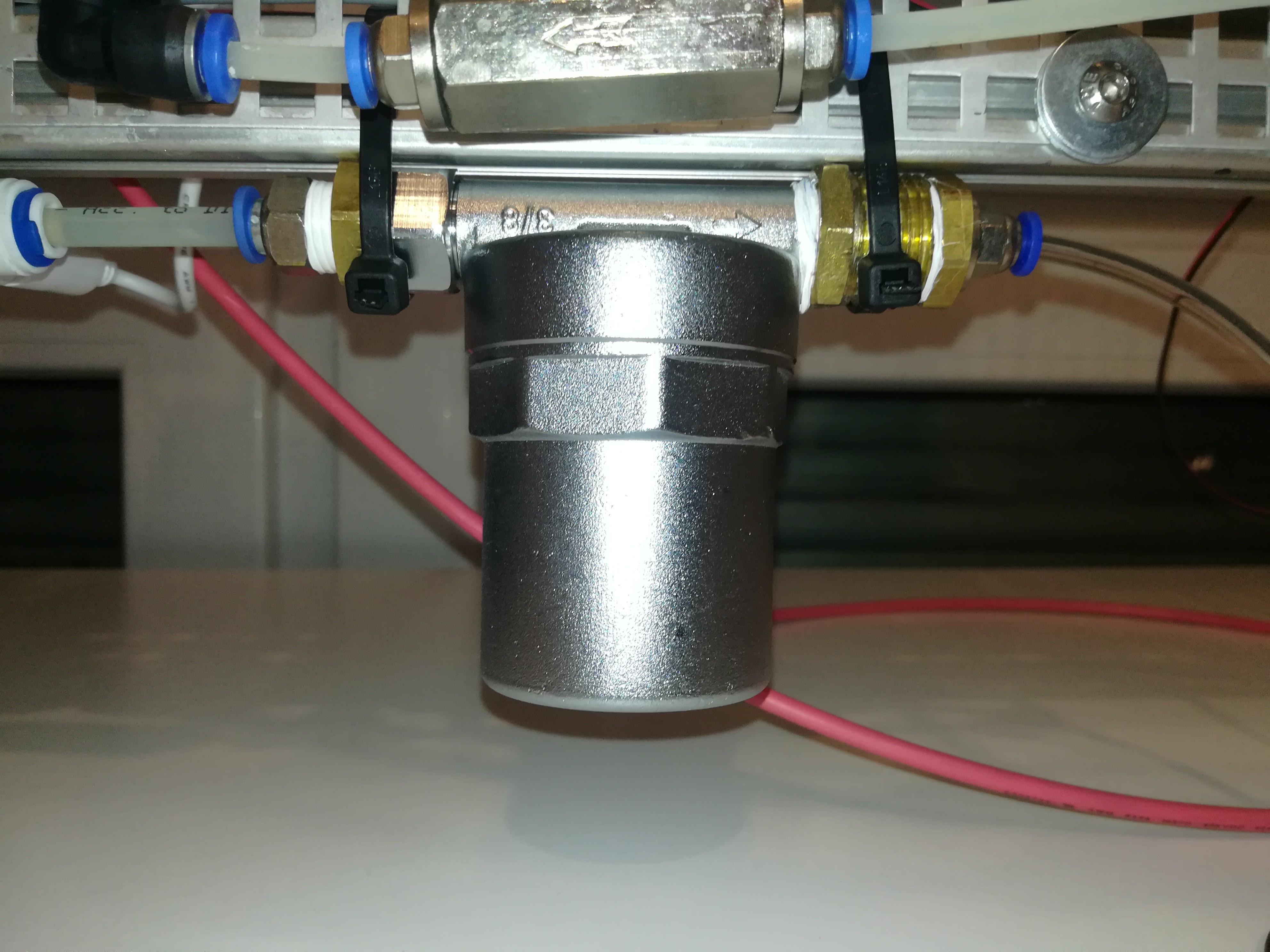
It turned out that the new filter was not corrosion resistant - what should be no surprise, given that it was made out of aluminum and galvanized steel, two materials which are not compatible with the ink....
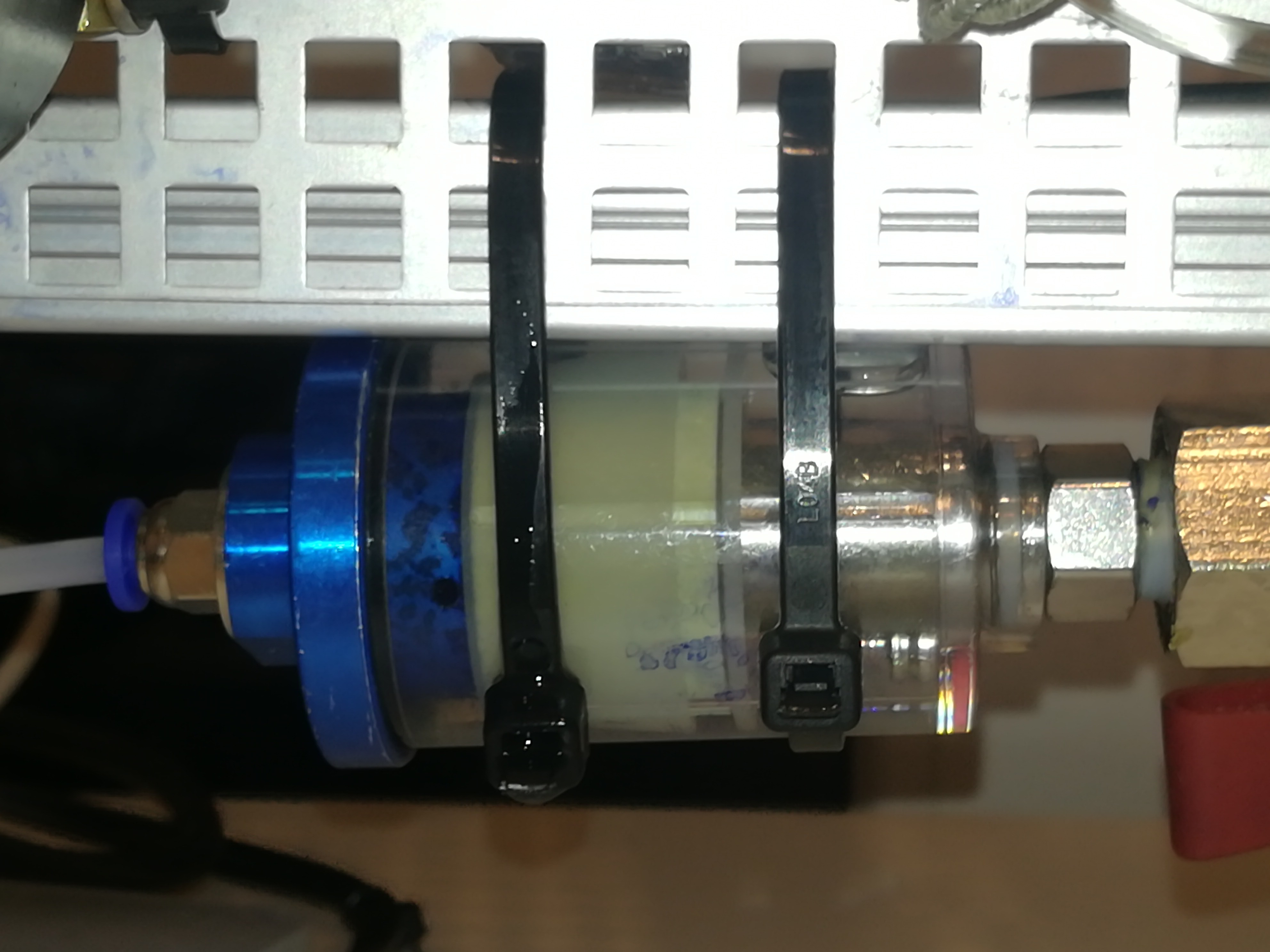
Because of that I'm now using a petrol filter again, like on the beginning of this project, but this time it is an steel free petrol filter.
There are many petrol filters out there which have galvanized steel parts in them which would start rusting and contaminating the ink. These are not suitable for the project and you have to use all plastic ones which are more corrosion resistant.
Petrol Filter without the Steel PartPetrol Filter connected with two 8mm to 4mm Push In Fittings
For now, this is the end of my report, and next up is the testing of the electrodes and trying to charge and deflect the ink stream.
I also want to test out mixing ink out of ethanol and PVB resin.
Besides a couple of low voltages, the CIJ printer also needs high voltages for the charging circuit and deflection plate.
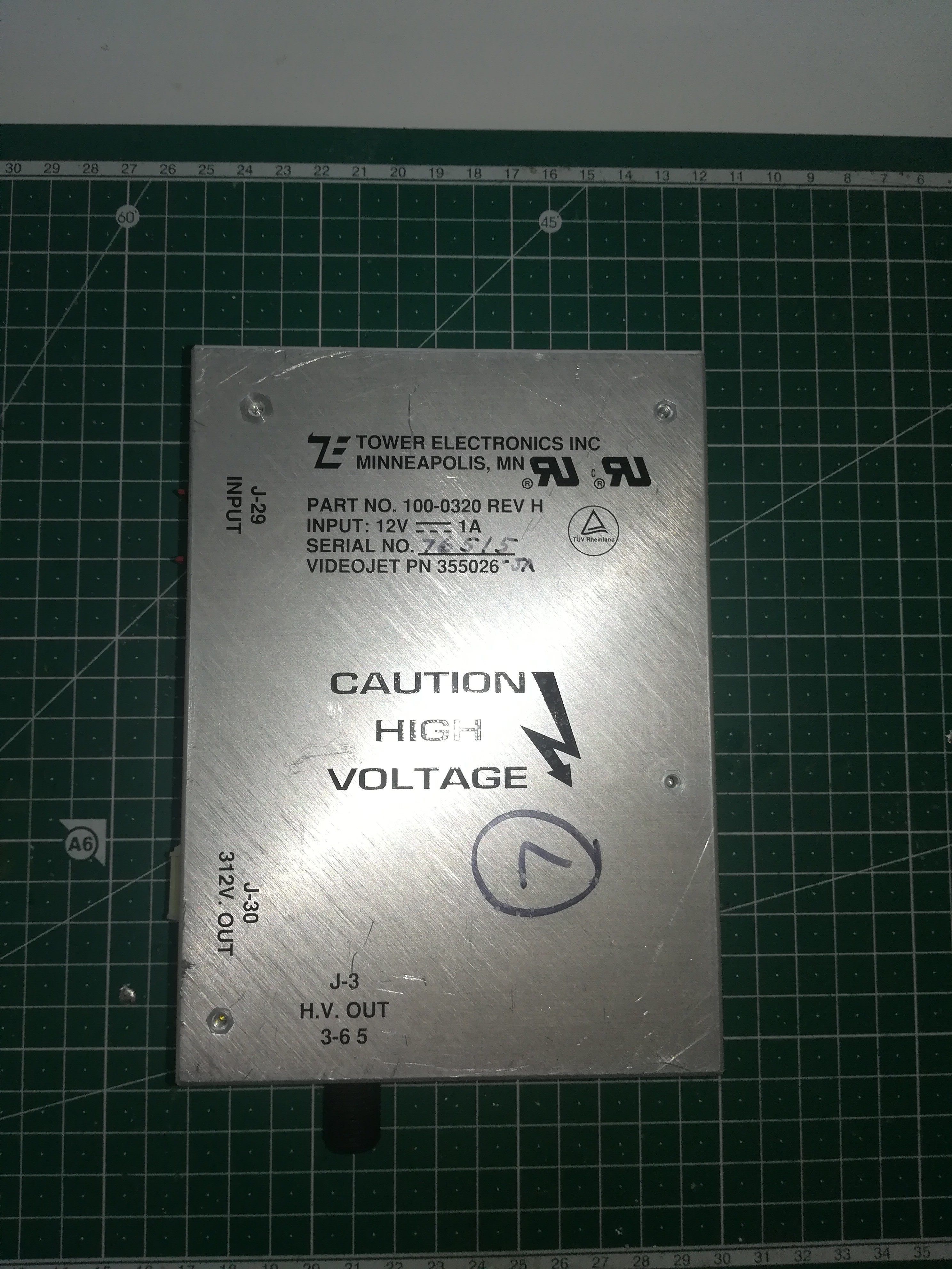
Here, you can see the power supply of an old CIJ printer that I bought for research:
It outputs 312V and 3 to 6 kilovolts. On this printer, the 312V is used for the charging circuit and the piezo driver, and the 3-6kv is used for the deflection plate.
On my printer, I'm currently using a 24V audio amplifier for driving the piezo, because they are available for sale and you don't have to build it by yourself which should make this part of the project easier.
I don't have the charging circuit ready so I can not fully test out if it works, but under the strobe led you can see droplet formation, so it looks promising.
However, if it turns out that the audio amplifier is not enough for driving the piezo I will have to build a proper piezo driver that uses the 312V for it.
Now I started looking for ways to generate 312V and 3-6kV.
312V Power Supply:
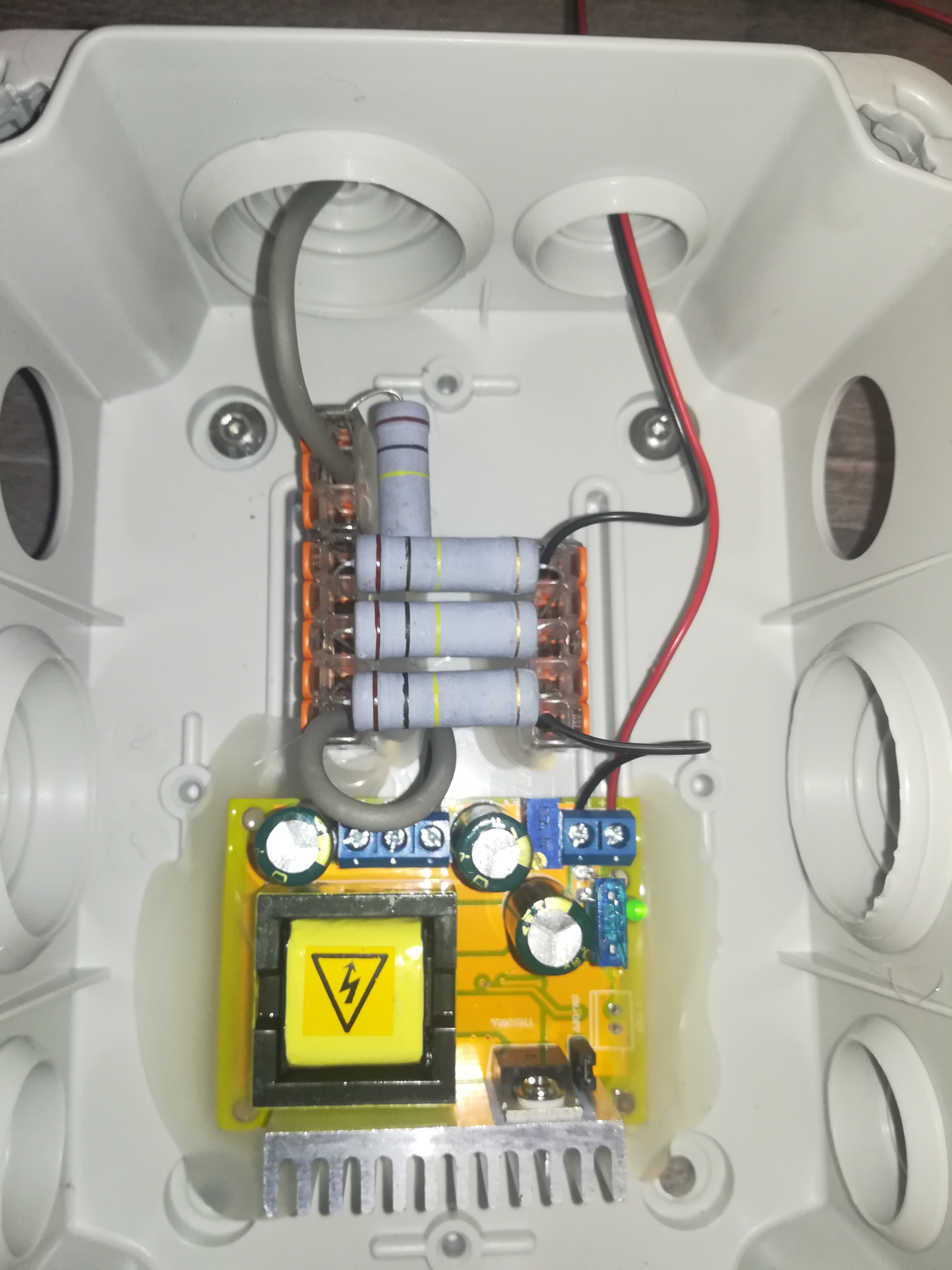
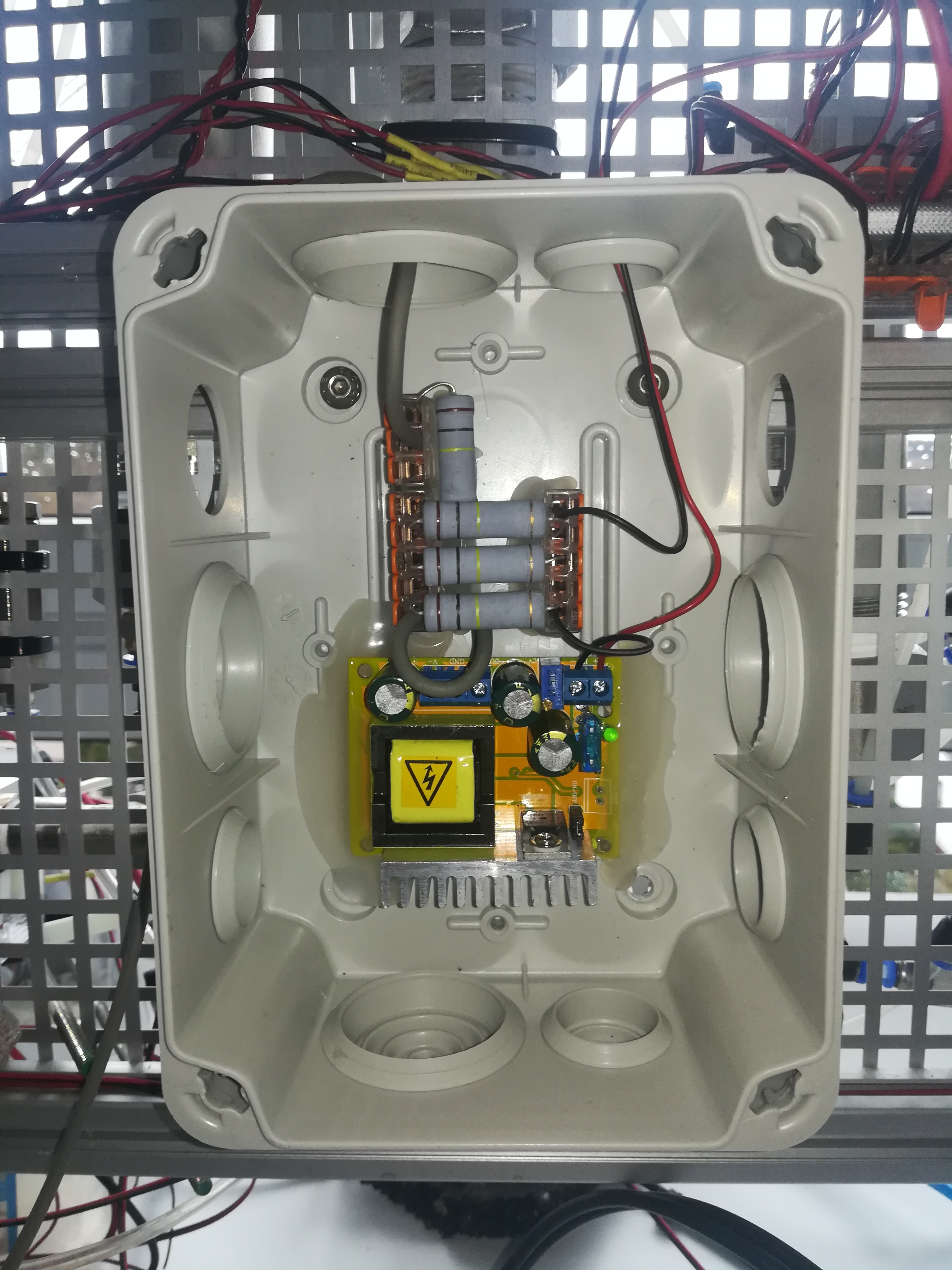
Here you can see my 312V power supply. I used a YH11068A boost converter powered by 12V. It turned out that the YH11068A needs some load to provide a stable output voltage and so I added three 100kOhm 5W resistors in parallel to the output. I also added another 100kOhm resistor in series with the output to limit the current for safety.
The YH11068A is protected by a 1A fuse on the input that will blow in case of an unintended current draw.
Finding out the thing with the needed load was a bit tricky, but because you can just buy the YH11068A, generating your 312V is not that complicated.
Adjustable 3-6kV power supply:
Here you can see my adjustable 3-6kV power supply. The output voltage can be adjusted by changing the switching frequency of the MOSFET.
Higher Frequency = Less Voltage
Lower Frequency = More Voltage
Because there was nothing out of the box available, I had to build it by myself.
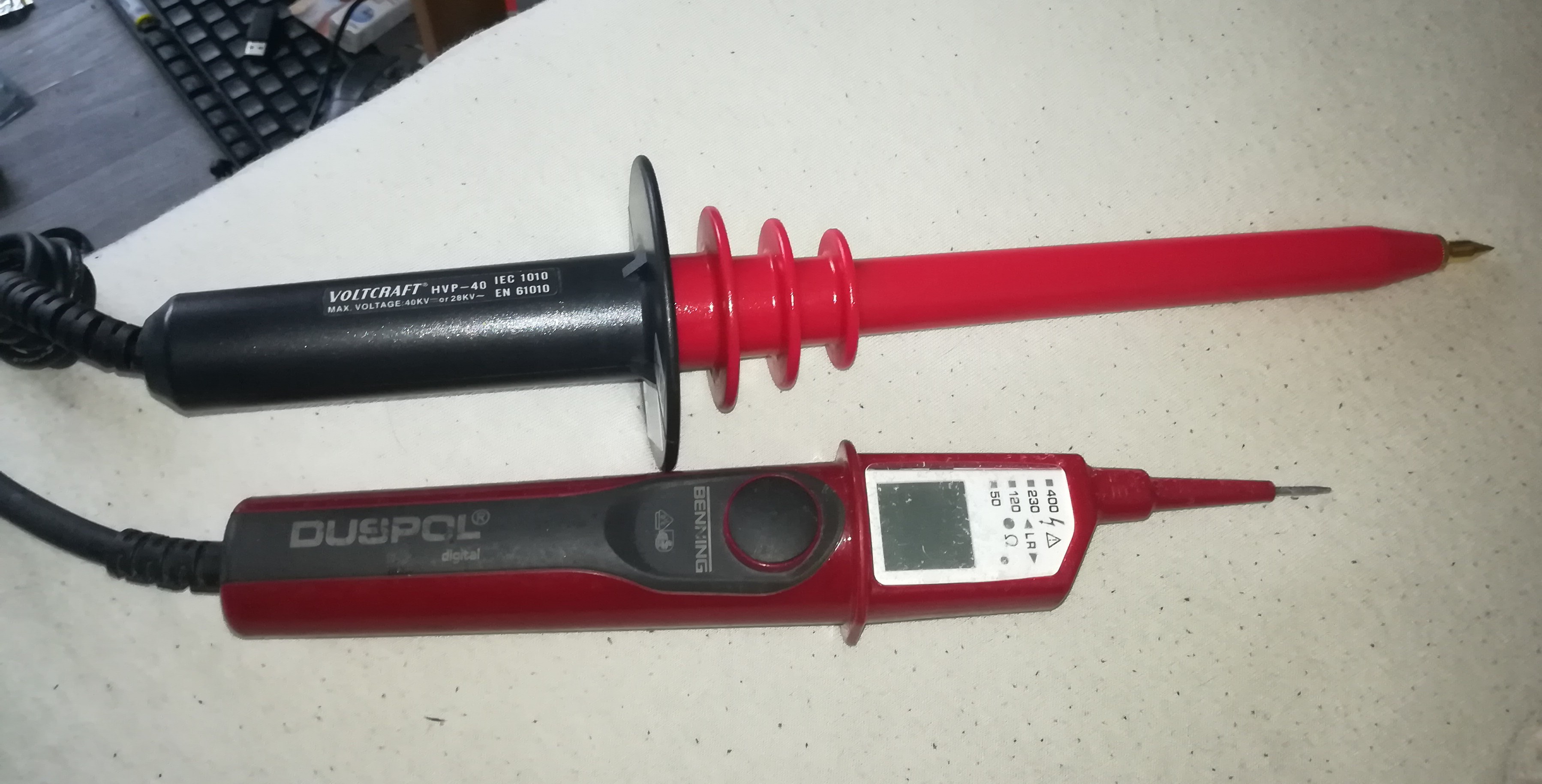
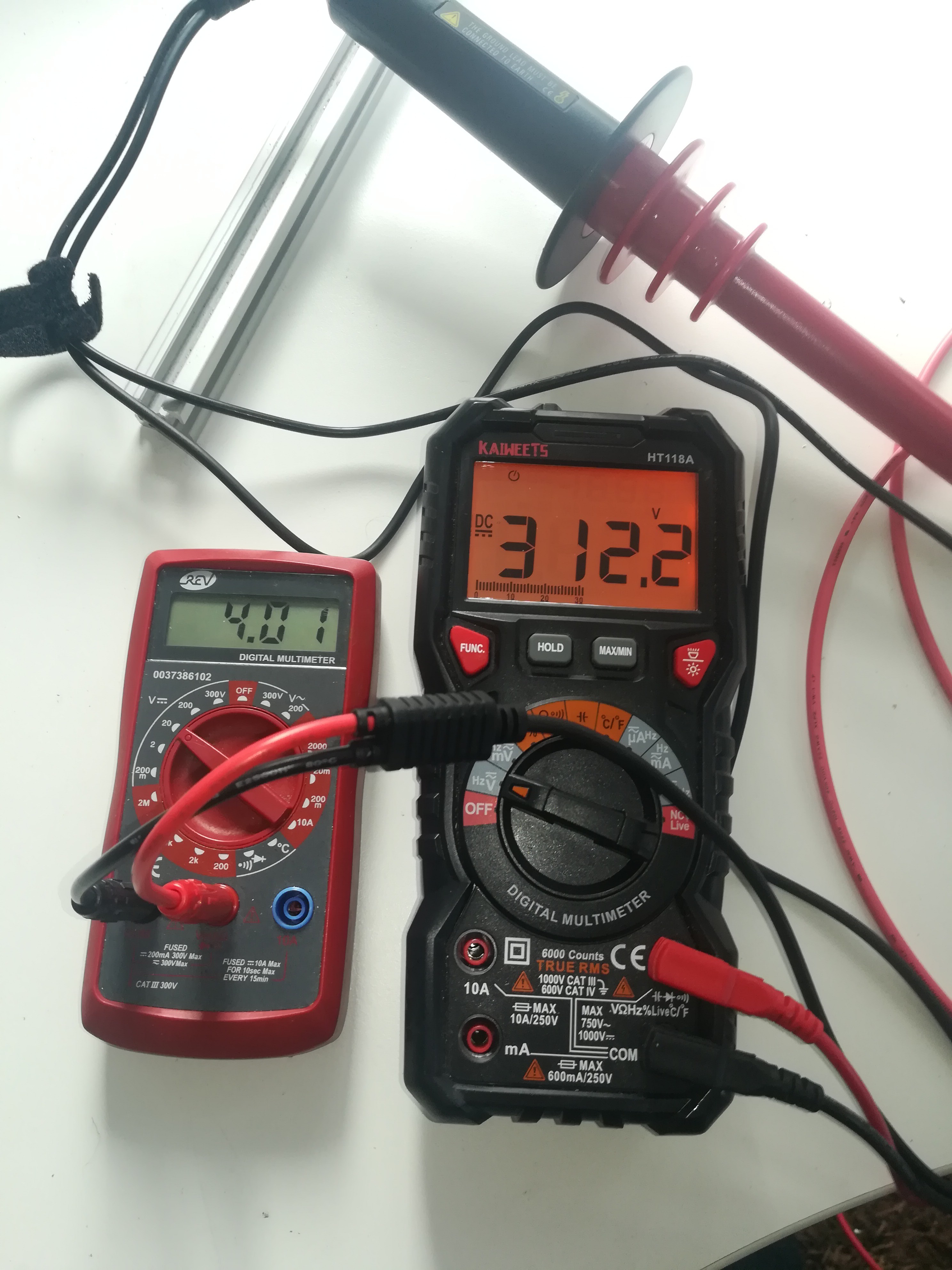
First, I got myself a high-voltage probe, so that I could measure the high-voltage output without destroying my multimeter. The probe divides the voltage 1:1000 so that you can read like 4.20V for 4200V on the multimeter.
After that, I looked for a circuit that can generate adjustable 3-6kV while being easy to build.
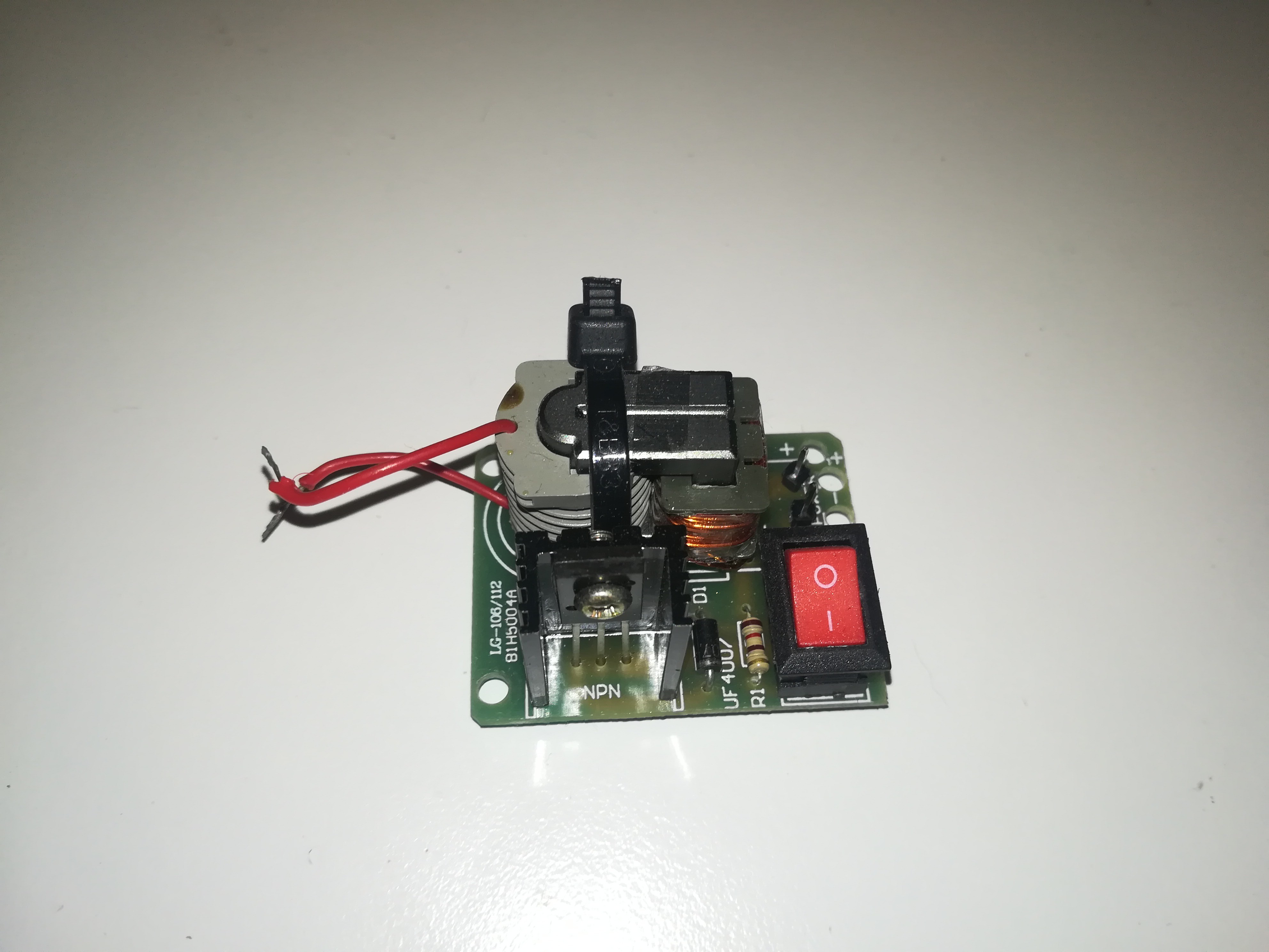
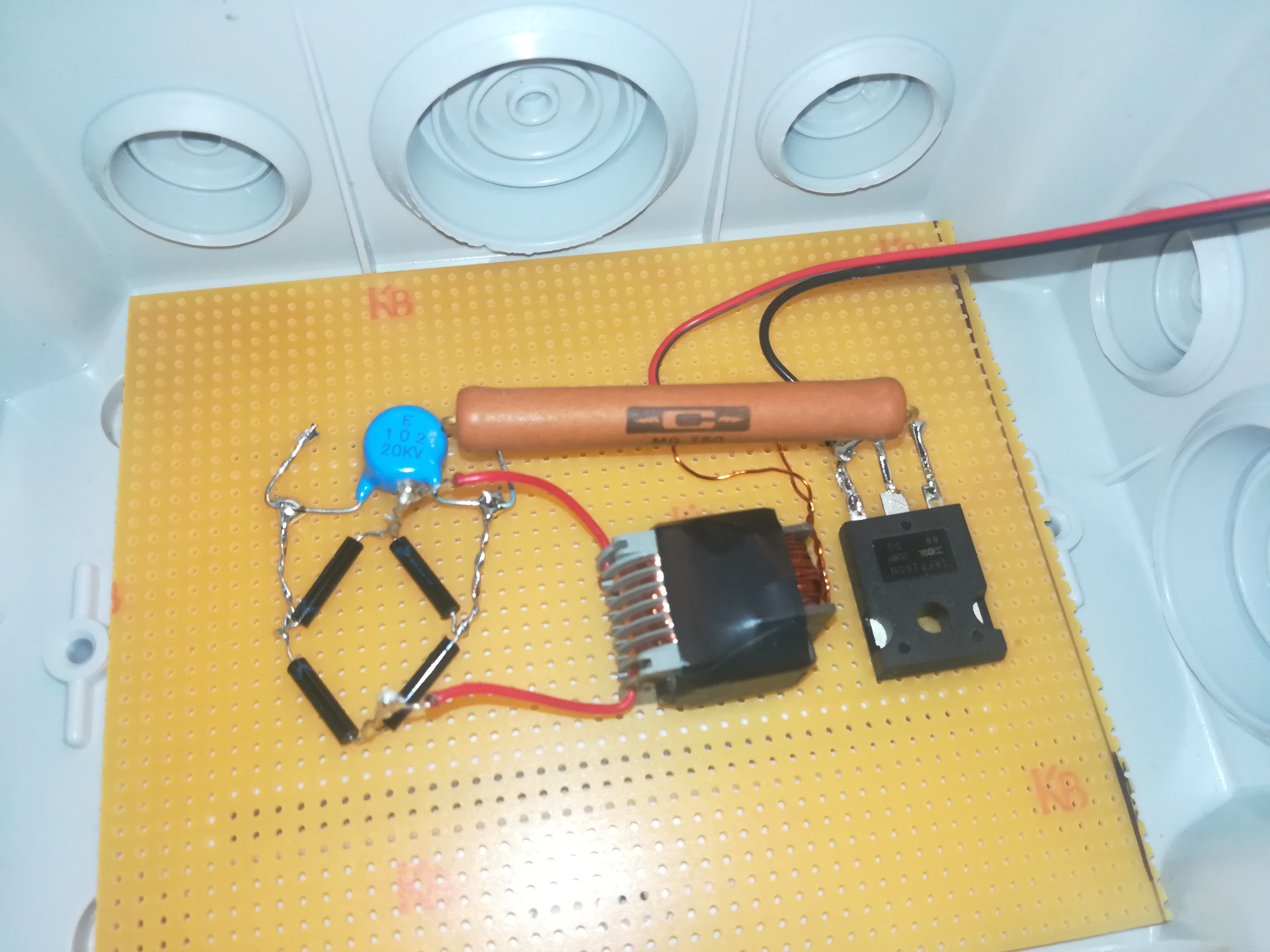
I started with one of these 15kV modules that you can find on Amazon, eBay, and Aliexpress.
This module uses a transformer that gets switched at high frequency by a transistor for generating high voltage. Besides the transformer's primary winding, it also has a feedback winding for controlling the transistor which makes the circuit self-oscillating, so that it does not need any sort of frequency generator to run.
Unfortunately, in contrast to a TV's flyback transformer, it has no internal rectifier diodes, so its output is AC. It also has no way of controlling the output voltage, so it can not be used for the CIJ printer without modification.
Besides that, the transformer that comes with the module is very nice for generating high voltages and because these modules are available almost anywhere, it should be no problem to build the circuit with the same transformer anywhere else.
The modules usually come as DIY kits, so there was no need to first desolder the transformer from the PCB.
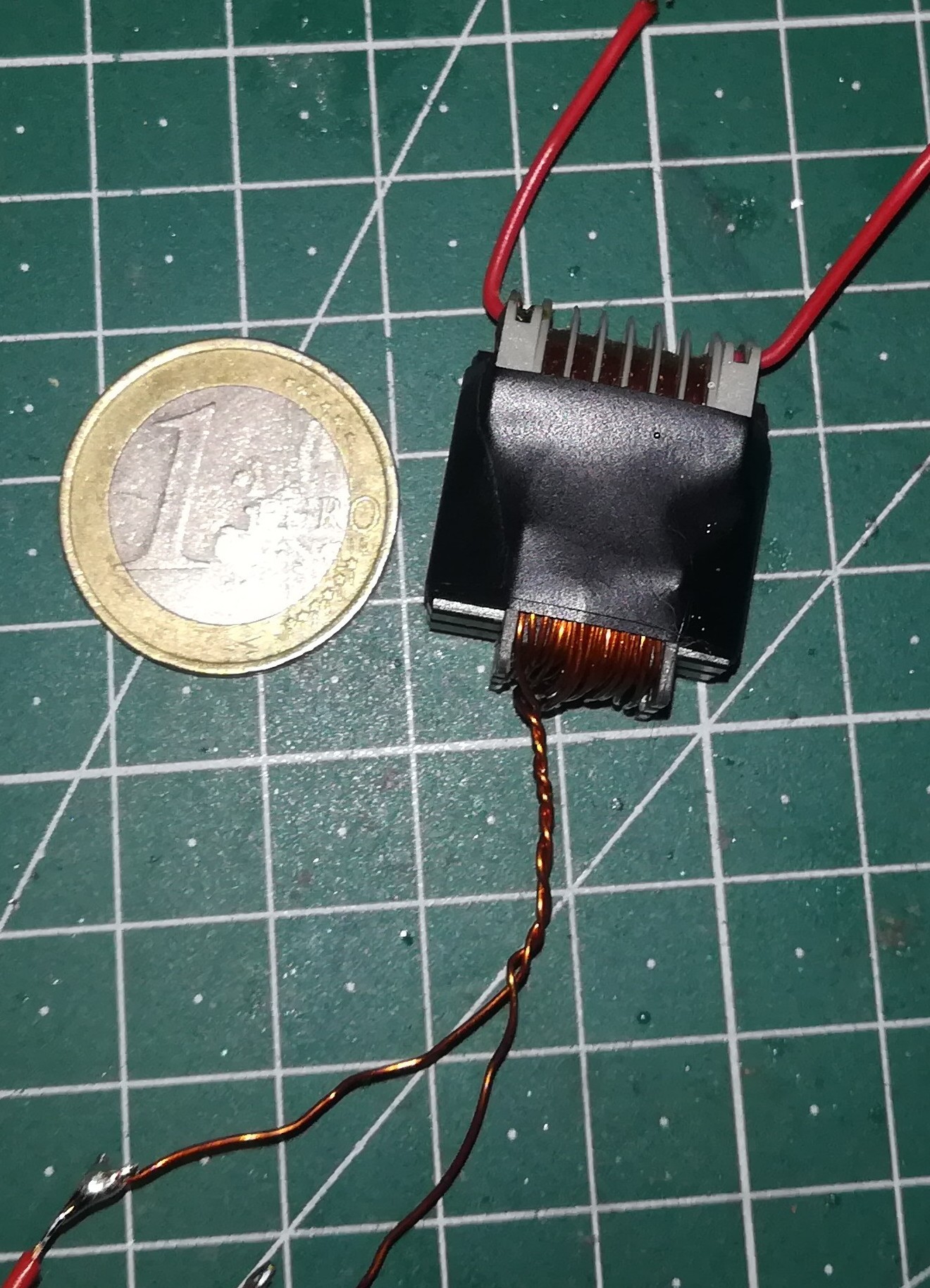
Instead, it was only needed to remove the feedback winding from the primary side of the transformer to get it ready for further use.
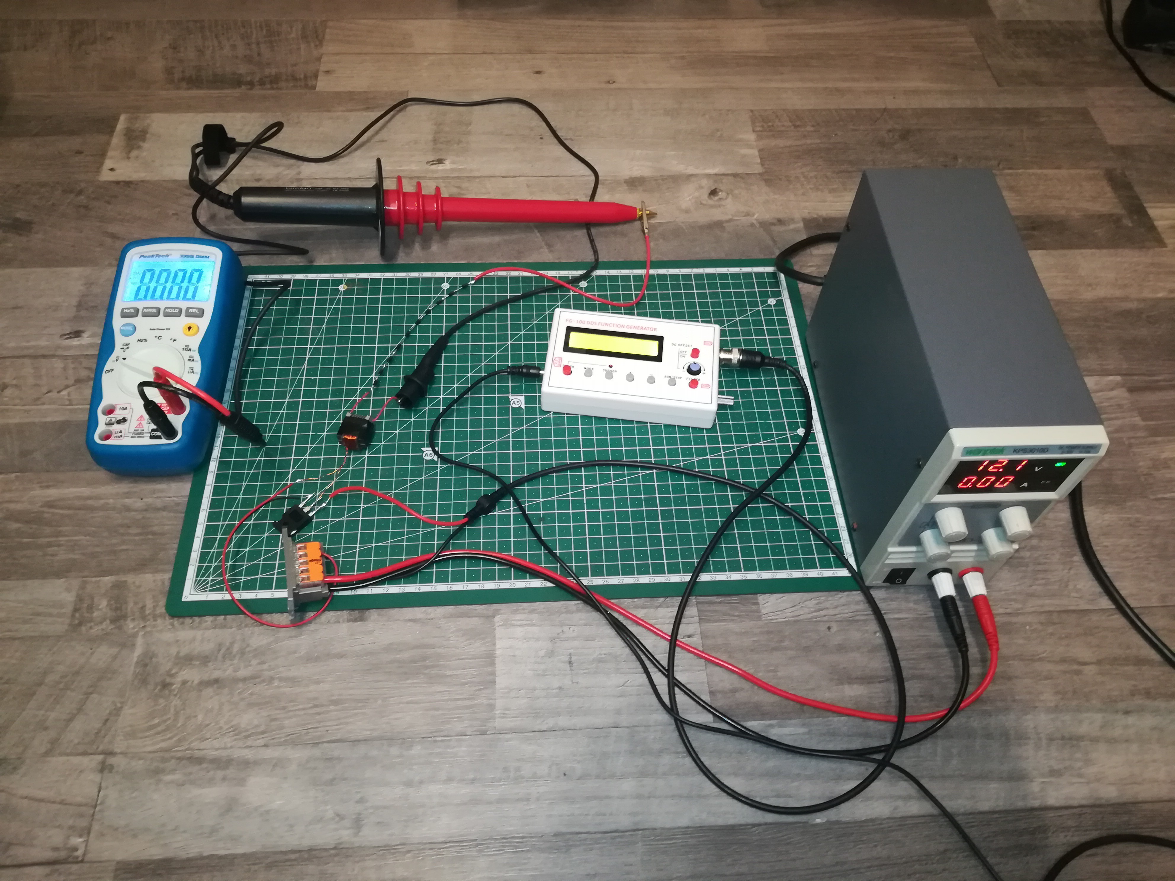
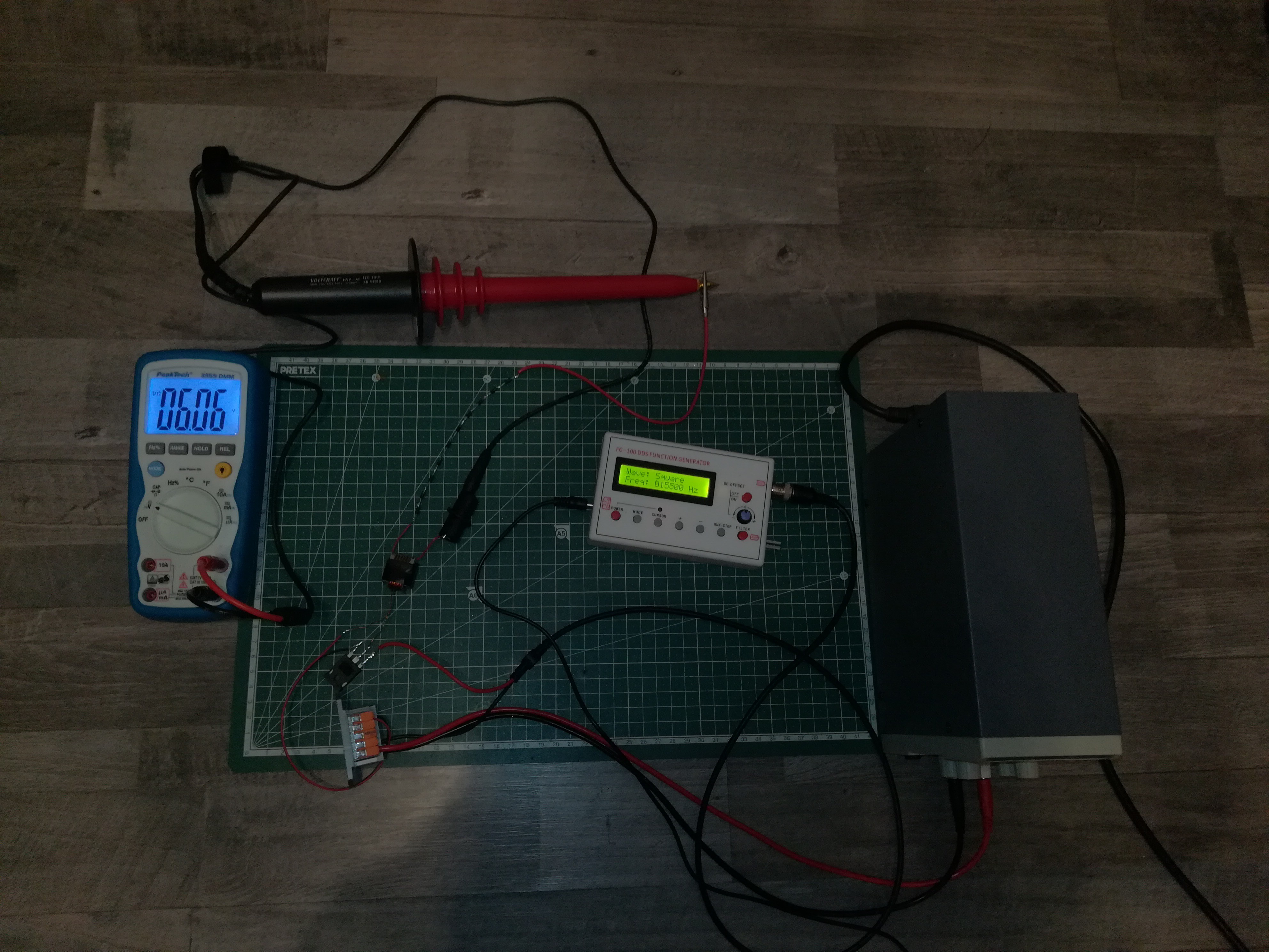
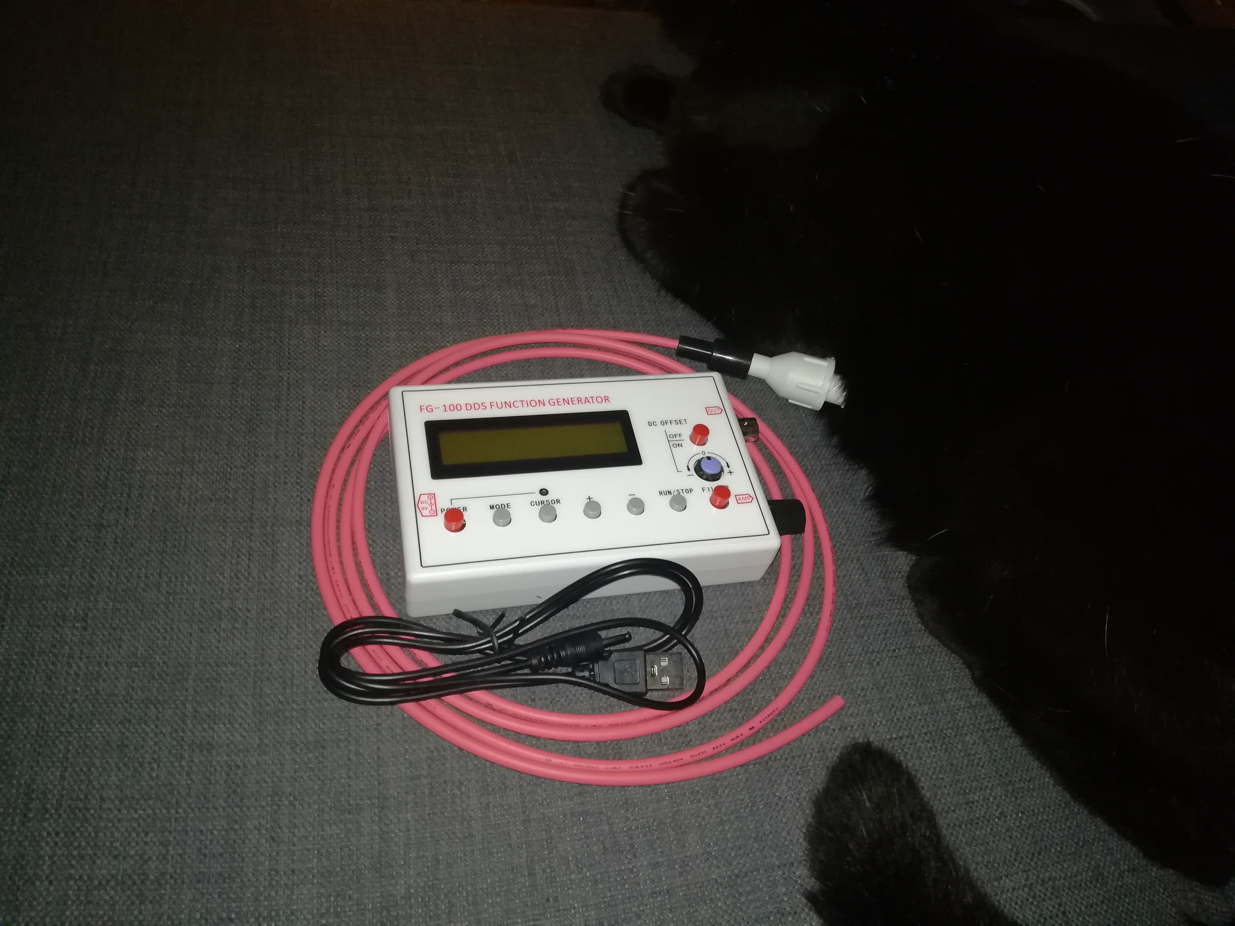
After removing the feedback winding I tried building a new transformer driver circuit, but this time driven by a function generator and an IRFP260 MOSFET. I also added multiple 1000V diodes in series to form a high-voltage diode that converted the output of the transformer to DC.
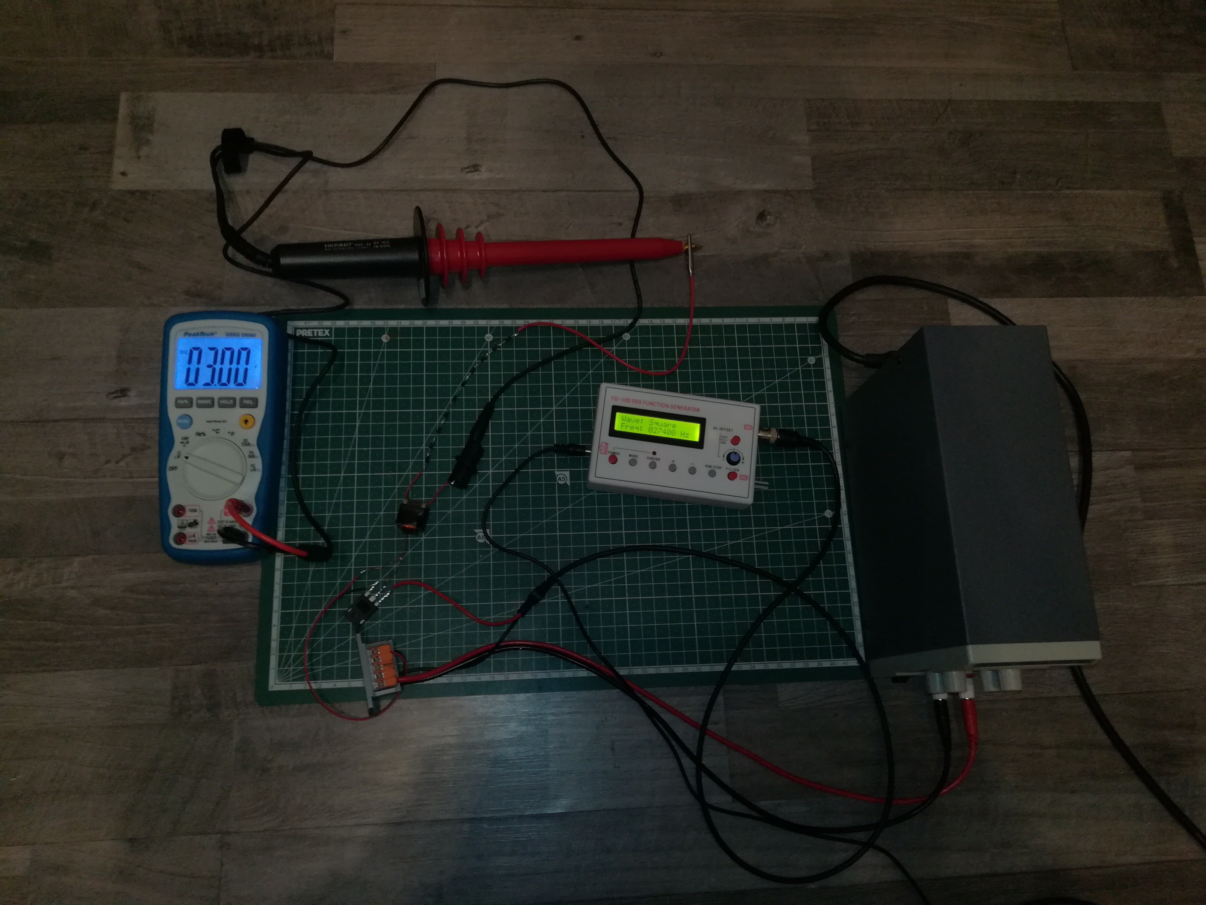
Here you can see my first high-voltage power supply testing setup
6060V @ 15500Hz
3000V @ 27400Hz
I tested out driving the MOSFET with PWM at different frequencies and noticed that the voltage at the output changed according to frequency as expected so I could continue with the work on the circuit.
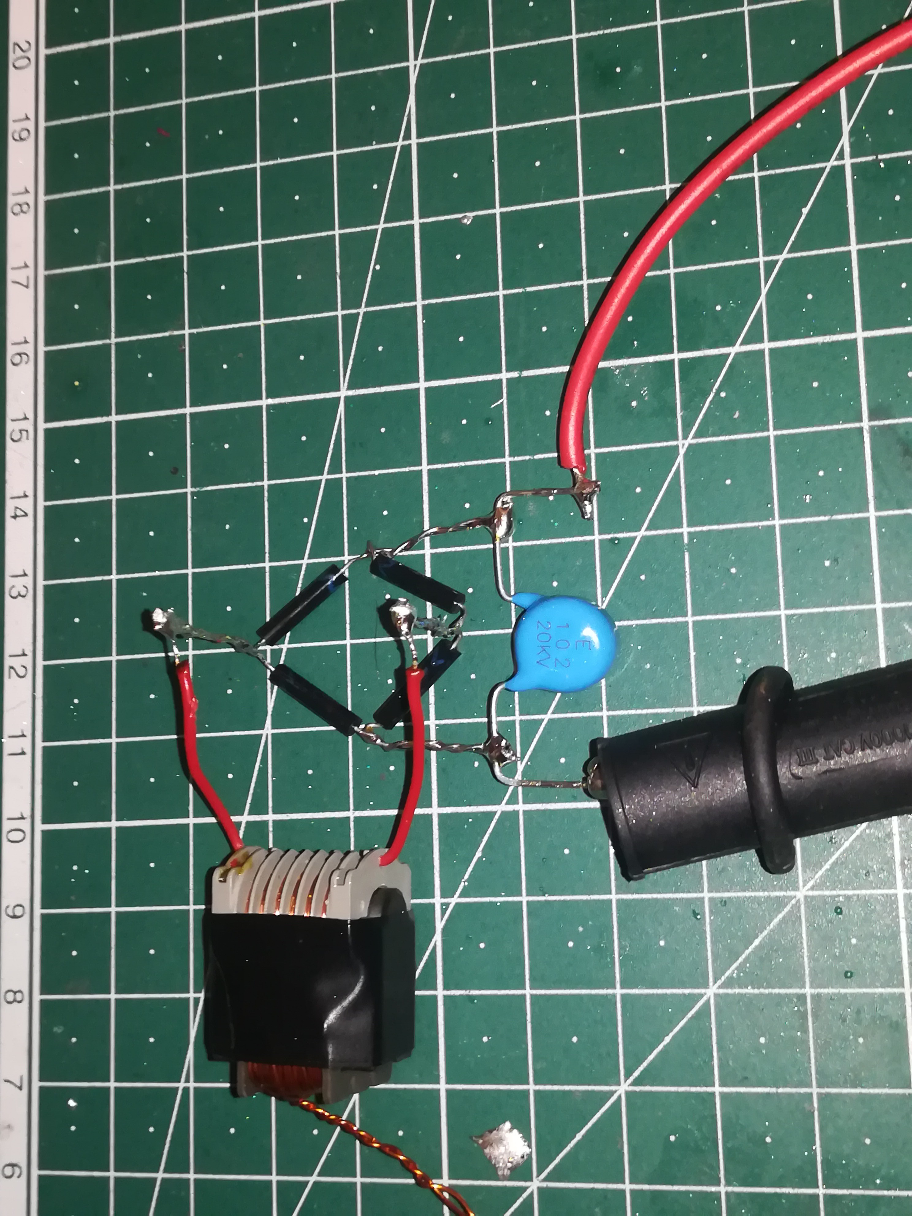
The diodes at the output could not provide real DC, but only the positive AC half wave and so I decided to build a bridge rectifier and add a capacitor to get rectified and smooth DC.
For that, I used four 20kV 5mA diodes to build a bridge rectifier and a 20kV 1nF capacitor for smoothing.
I tested it out and realized that I now could get a higher voltage with the same frequency.
I also tested out drawing some arcs and shorting the circuit, to find out what happens.
Unfortunately, in contrast to the last test circuit, with the capacitor added the circuit could provide enough current to destroy not only the MOSFET but also the function generator :/
Now, I had to find a way to limit the current to a safe level to prevent damage to the electronics in case of a short circuit. It later turned out that short circuits happen from time to time if the high voltage deflection plate gets unintended hit by some droplets.
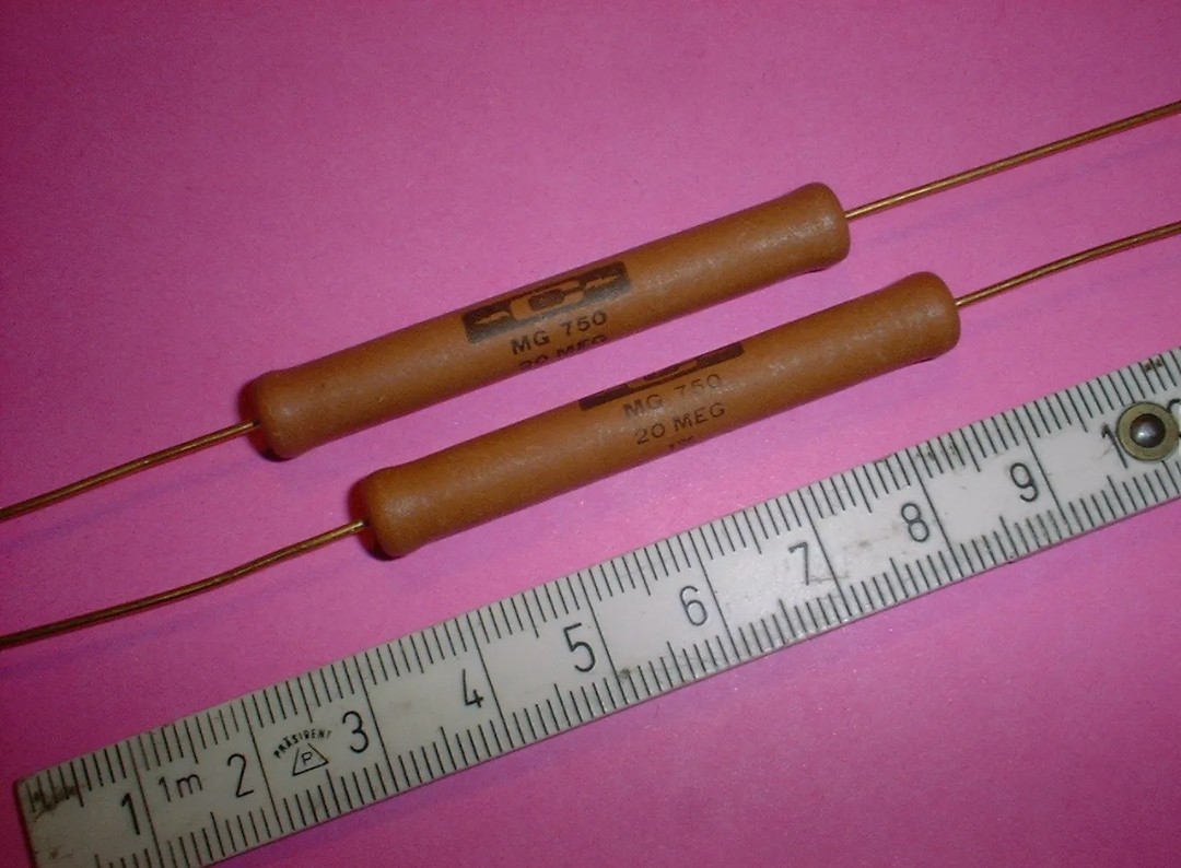
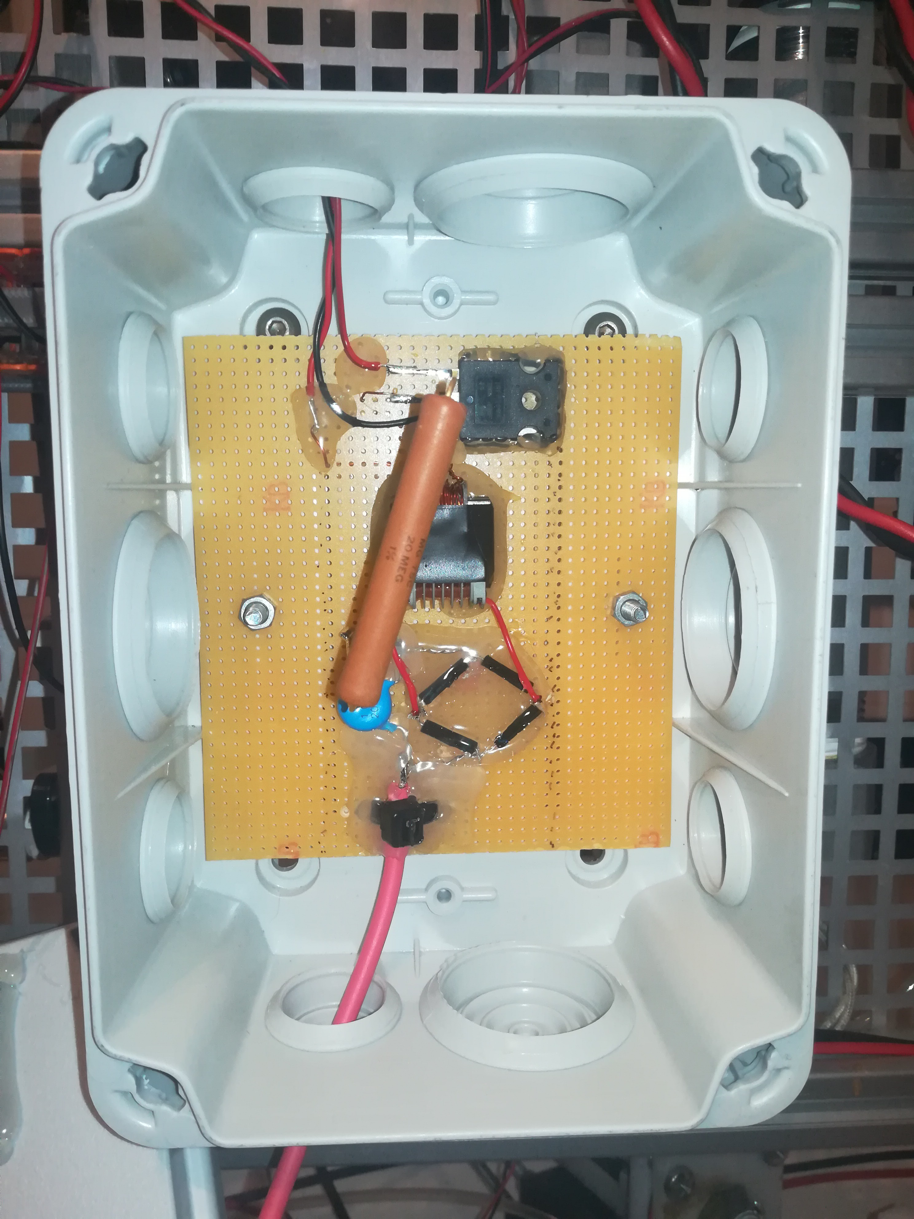
So, I got myself some 20mOhm 5W high voltage resistors to limit the current to a safe level for the electronics and also for the user.
I added the resistor between the negative high voltage output and GND. Now it's possible to short the high voltage to ground without causing damage to the electronics.
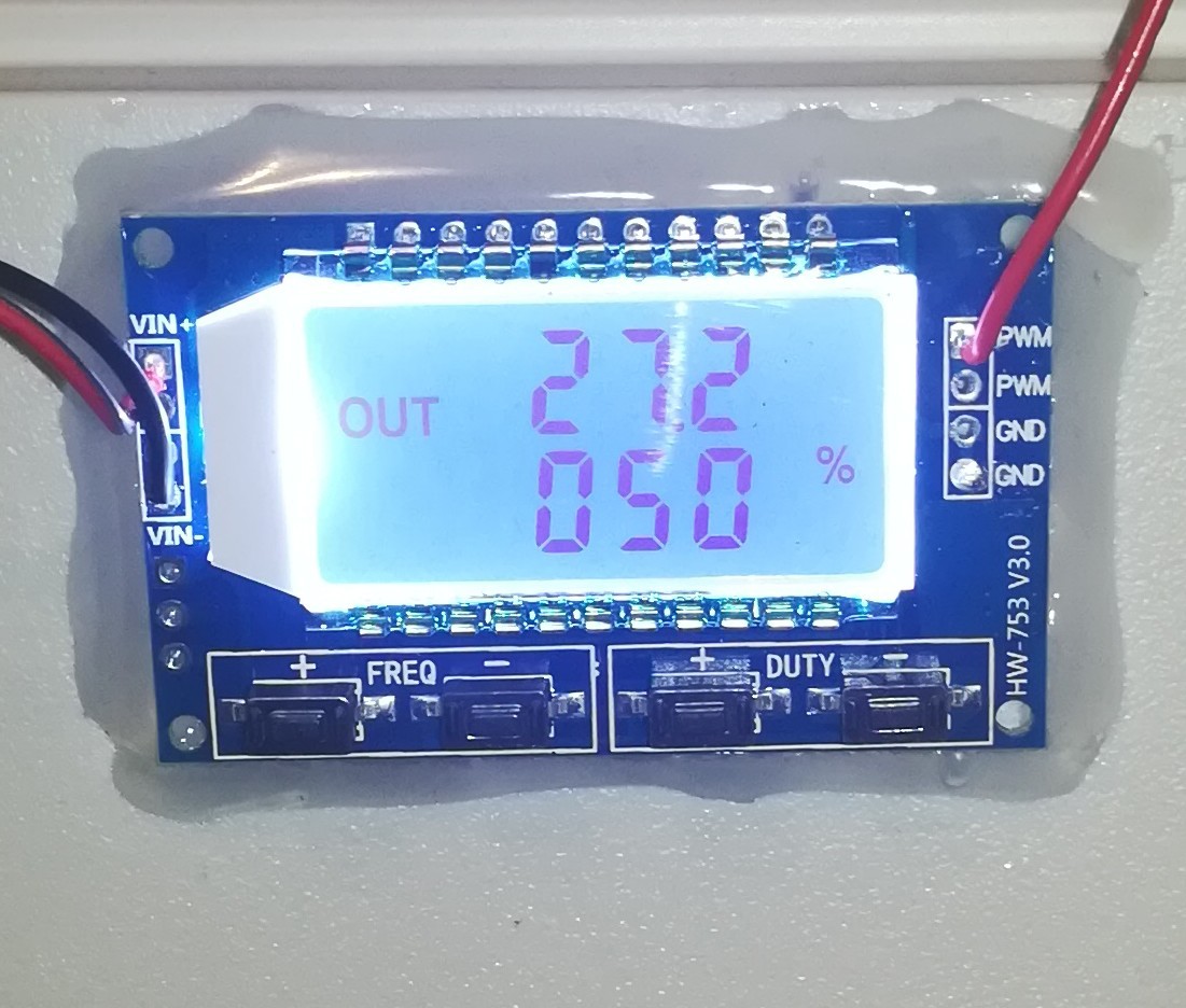
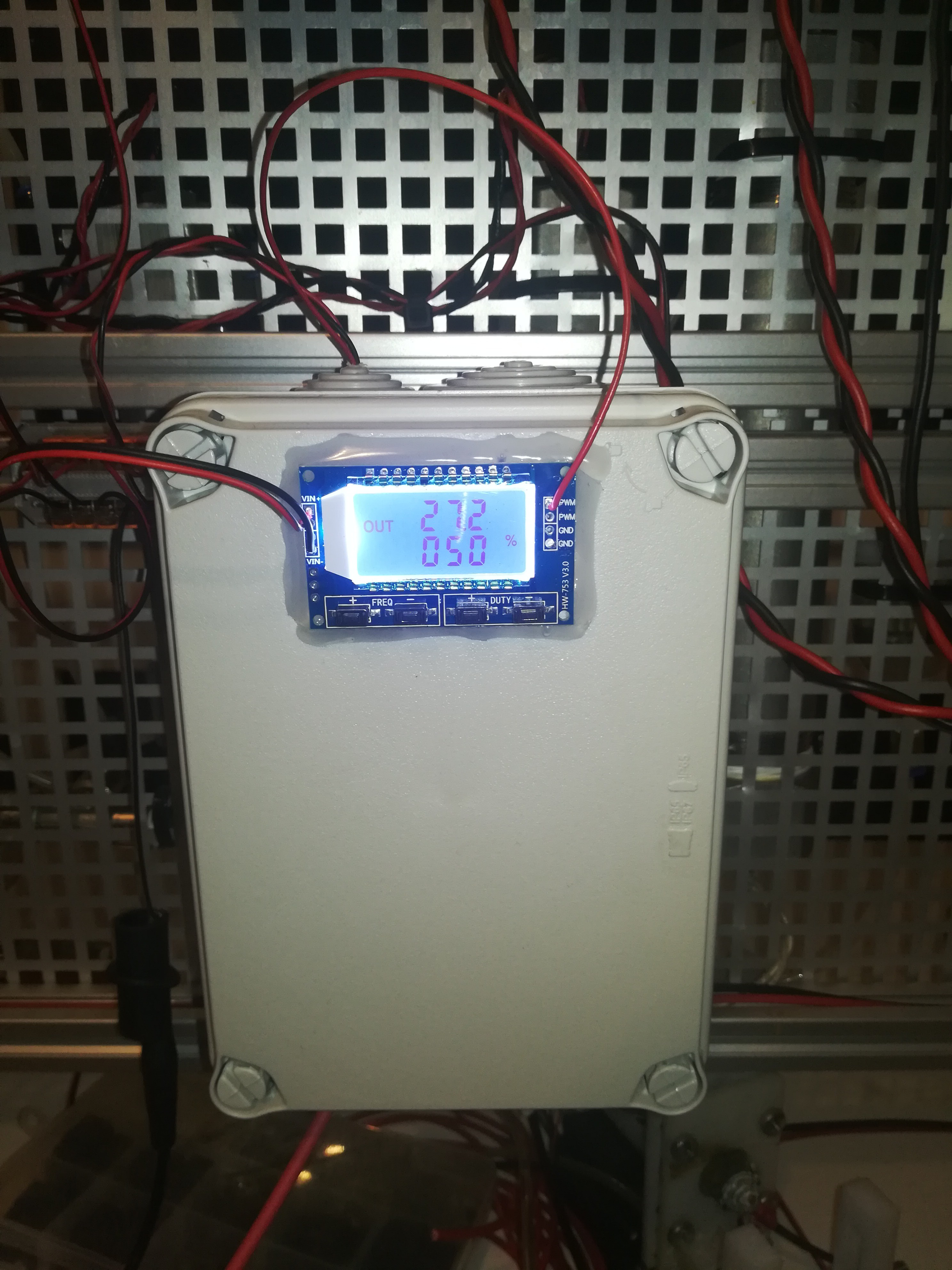
While waiting for a new function generator and a high-voltage cable to arrive, I tested out the nice XY-LPWM generator with integrated LCD, that I wanted to use for adjusting the switching frequency and with that the voltage of the high-voltage deflection plate.
The cable arrived and I could finally fix all parts with hot glue onto a hard paper that I mounted into an electronics box which I mounted on the printer frame.
Finally, I added a switch and a 1A fuse to the input of the high-voltage power supply and connected the high-voltage cable to the deflection plate.
With that, the work on the 3-6kV power supply was done.
Here you can see both power supplies running
And here you can see a test of the 3-6kV power supply.
With that, I finally have all needed voltages ready to drive my CIJ printer prototype.
 Dominik Meffert
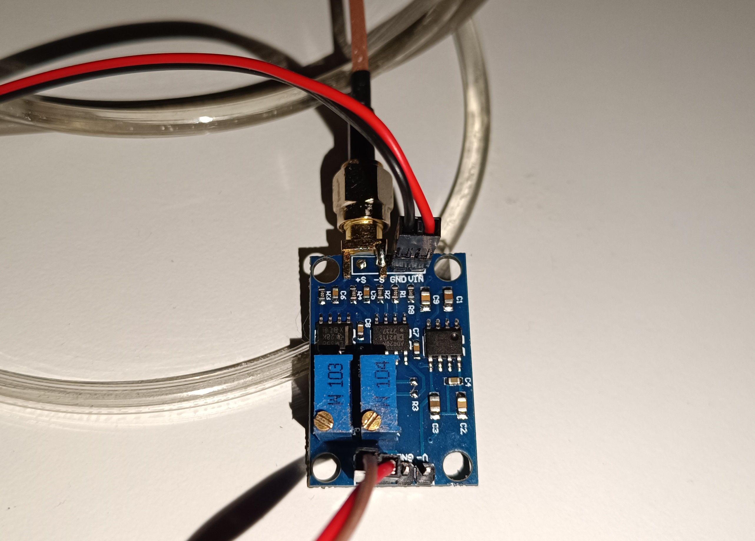


 Here you can see my adjustable 3-6kV power supply. The output voltage can be adjusted by changing the switching frequency of the MOSFET.