 Pablo Antonio Camacho Jr.
Full journey of how the idea came to be is documented here. https://tinyurl.com/mrv8dzr5
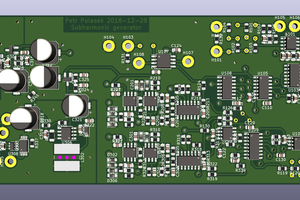
This is a general overview of how the game logic circuit works.
Player Coordinates
Player coordinates are set by the joysticks. The vertical axis of the joystick sets the y value. The horizontal axis of the joystick sets the x value.
Collision Detection
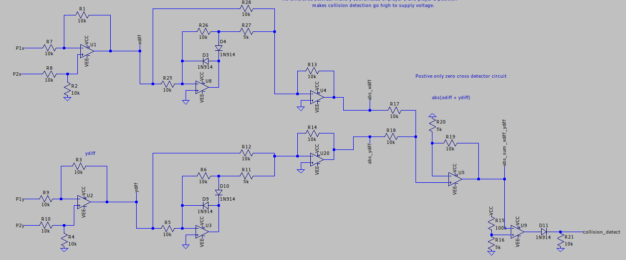
Collision detection is observed by looking at whether the difference between player coordinates are the same or very little with the formula below. The formula is implemented with op-amps.
diffsum_result = | xdiff | + | ydiff |
Same coordinates: diffsum_result = 0 , Close-enough: diffsum_result = 0.1V.
Collision detection test. Collision detection signal goes to 2.7V when both joysticks are in the same position.
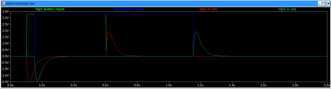
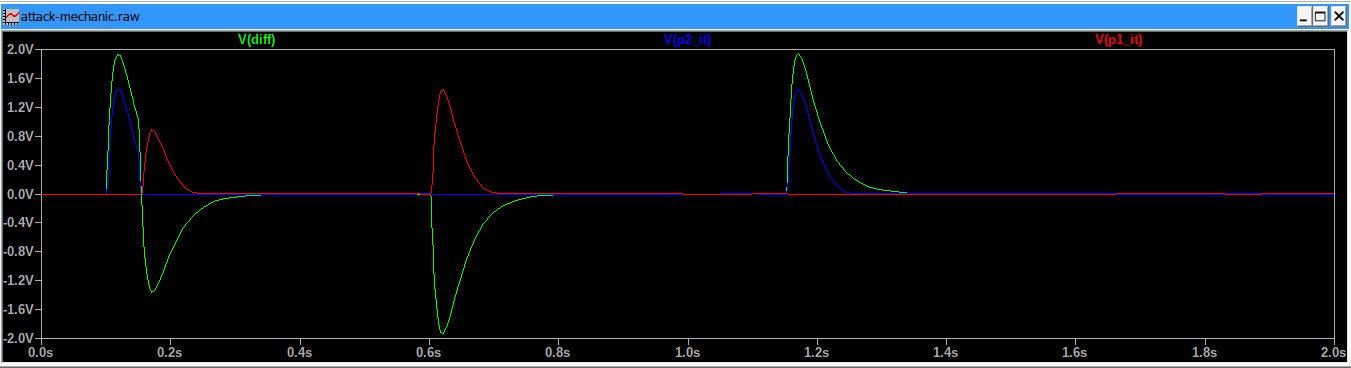
Player Attacks
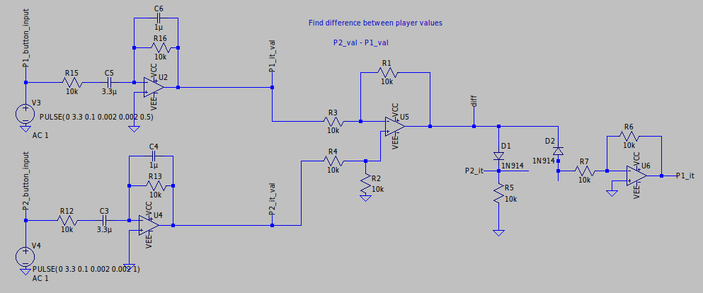
Player
attack involves tracking the button release of the button by taking
the derivative of the square wave made by the button press. A
differentiator circuit produces a negative exponential voltage RC
discharge curve on the rising edge of the square wave and a positive
exponential RC discharge curve that describe the attack
value(player_it_value).
The difference between attack values of the players are measured and put into diff signal. Diff signal is positive if player 2 attack value is more than player 1 attack value, and negative if player 1 attack value is more than player 2 attack value.
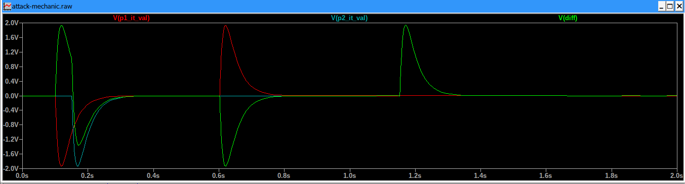
Player with the biggest attack power has a certain switch activated indicating that they are "It" and have the biggest attack power. Player 1 becomes “It” and is indicated as having the biggest attack value in p1_it signal if the diff signal is negative. Player 2 becomes “It” and is indicated as having the biggest attack value in p2_it signal if the diff signal is positive.
If players are near enough and one player has a bigger attack than
the other player, then, a winning player switch is
activated.
Rendering
The game
is intended to be rendered on various systems e.g. PC, TV,
oscilloscope. An example of a rendering that has been done is on the
PC in which an stm32 microcontroller digitizes the analog output
signals from the game(e.g. player coordinates, p1_it and p2_it status
signals, etc.), passes these signals to PC via a USB-UART bridge, and
then C++ code interprets the signals and draws what is happening in
the game world.
The way rendering works on the PC is that
it is split into 2 separate processes. The rendering of ADC values is
done in the main thread and reading and storing ADC values from UART
is done in a separate thread. Rendering and updating adc buffer must
be done in separate threads or else rendering would slow down adc
buffer update process which stalls rendering from drawing the latest
adc buffer values. Mutex
is used to lock the ADC buffer to give exclusive access to the ADC
buffer when updating or reading from it.
Video Results

 MS-BOSS
 UTSOURCE
 Russell Kramer
 kamalkedin123
Updated project. Circuit uses different attack mechanic now. Added more videos and images for explanation.