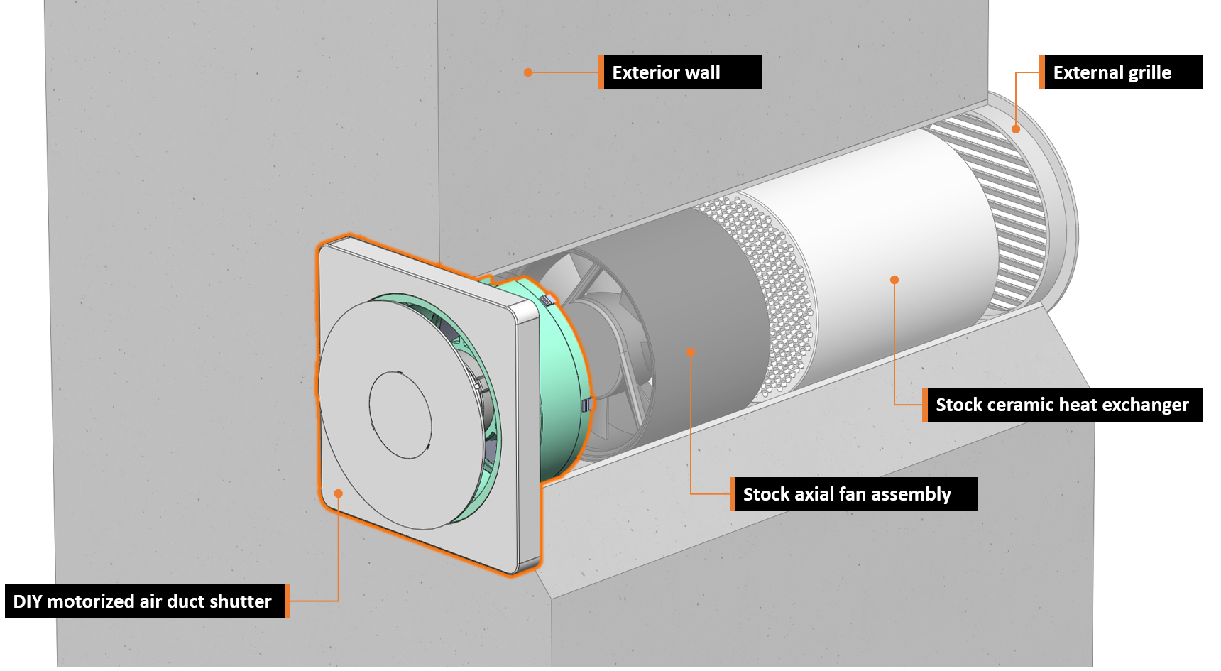
Close
0%
0%

AutoDuct smart motorized air duct shutter

Smart motorized air duct shutter with wireless connectivity for decentralized ventilation systems

Public Chat
Similar projects worth following
The AutoDuct system prevents heat loss and high cost for heating in apartments with decentralized ventilation systems.

AutoDuct is a smart DIY air duct shutter for decentralized ventilation systems in residential buildings. Its main purpose is to automatically control airflow and block outside noise using a 3D-printed shutter system. This solves the problem of unintended air flow into the apartment during cold and windy days to increase comfort, maintain energy efficiency and reduce expenses for heating.
The integrated electronics of the air duct shutter assembly also gives full control of the ventilation system’s fan to enable features like flexible ventilation schedules and automatic humidity control. The Bluetooth low energy interface lets you control and configure the system via a mobile app. Multiple ventilation units can also be integrated into Apple HomeKit via a simple ESP32-powered BLE-to-Wifi-bridge.


Mechanical Assembly

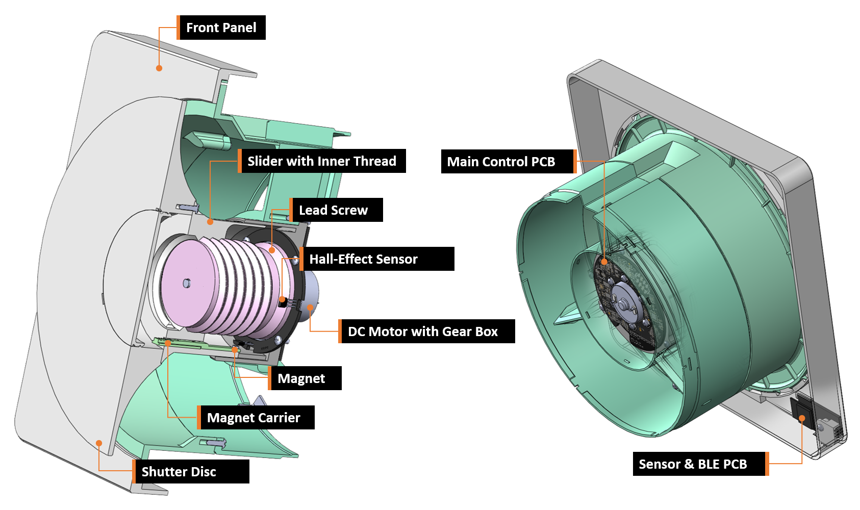
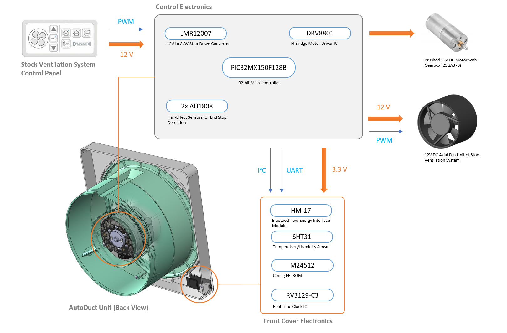
At the heart of this device is a mostly 3D-printed linear actuator which is used to open and close a shutter disc to prevent unwanted airflow. The 3D-printed leadscrew of the actuator is directly attached to a small brushed DC motor with an integrated gearbox.

Integrated into the encapsulated actuator unit two hall effect switches on a separate ring-shaped PCB are used to detect the end stop positions (open/close) of the shutter mechanism in combination with tiny magnets. The axial position of these magnets can be adjusted to compensate for mechanical tolerances in the assembly.

Note: the actuator unit does not use any additional (ball) bearings to keep the BOM simple and material cost low. Axial and radial forces are solely absorbed by the 3D-printed linear guides and the integrated bearings of the geared motor. This could potentially reduce longevity of the assembly but has not been an issue while testing multiple units over more than a year now. Use of silicone grease is highly recommended. 

Electronics

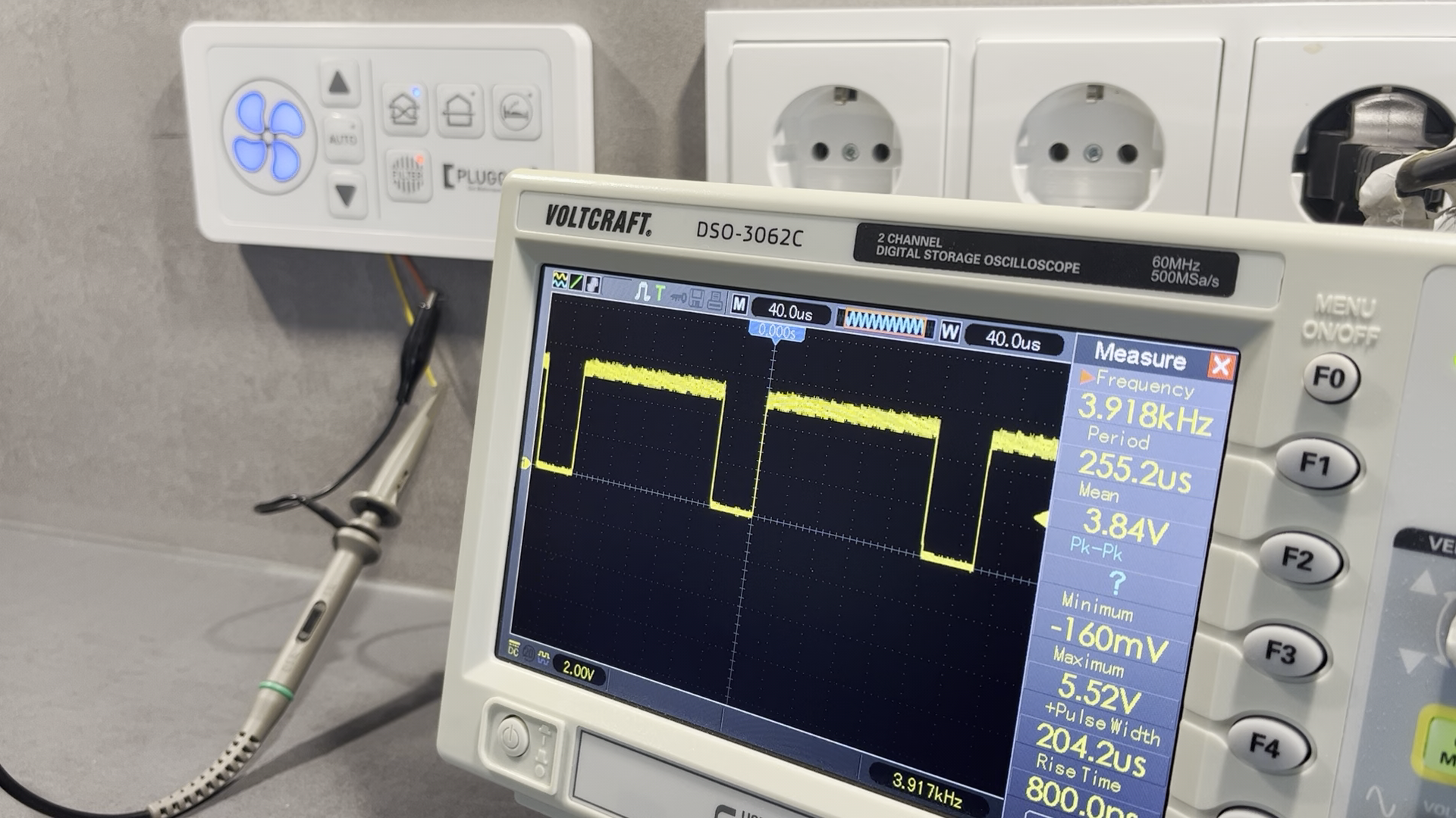
The electronics are based around a Microchip 32-bit microcontroller (PIC32MX), which might be a little bit overpowered for this project but was available from a previous project and has a neat footprint. The +3V3 rail is generated from the +12V bus by a step-down converter. The geared DC motor is driven by a dedicated H-bridge driver IC (DRV8801).

Behind the front cover of the assembly another small PCB is hidden. This PCB contains the Bluetooth low energy module (HM-17), a serial EEPROM, a real time clock (RTC) IC and a humidity and temperature sensor. User feedback is given via a white LED which shines through the 3D-printed enclosure and has brightness control via PWM.

Firmware

The main processor of the device (PIC32MX150F128B) runs a super simple multitasking OS which takes care of these main tasks:

  • monitoring of fan control PWM signal from the stock ventilation system control bus
  • reading of temperature / humidity from SHT31 sensor
  • generating the PWM control signal for connected fan
  • motor control including end stop detection
  • handle the BLE communication when the system is connected to the mobile app or the HomeKit-to-BLE bridge

Depending on the selected operating mode, the device will perform the following actions:

  • opening / closing the valve based on the detected fan control PWM signal
  • automatically activating the fan based on schedule events or humidity thresholds
  • react to remote control commands issued via the mobile app / BLE connection

A custom bootloader was developed which enables over-the-air firmware updates via the Bluetooth low energy interface.


VentAdapter.STL

Air duct adapter / outer shell of AutoDuct assembly

Standard Tesselated Geometry - 28.99 MB - 09/11/2023 at 20:02

Download

PistonSliderMod.STL

slider component of linear actuator with inner thread

Standard Tesselated Geometry - 24.56 MB - 09/11/2023 at 20:02

Download

FrontCap.STL

front cover / cap

Standard Tesselated Geometry - 13.32 MB - 09/11/2023 at 20:02

Download

Centralizer.STL

main body part of linear actuator

Standard Tesselated Geometry - 16.48 MB - 09/11/2023 at 20:02

Download

WingRing.STL

outer shell of AutoDuct unit with carrier ring for linear actuator. Cable guide channels integrated into two of the 3 wing structures.

Standard Tesselated Geometry - 16.55 MB - 09/11/2023 at 20:01

Download

View all 18 files

  • 1 × HM-17 Electronic Components / Bluetooth low energy interface module
  • 1 × PIC32MX150F128B Microprocessors, Microcontrollers, DSPs / ARM, RISC-Based Microcontrollers
  • 1 × LMR12007 Power Management ICs / Switching Regulators and Controllers
  • 1 × DRV8801 H-Bridge Motor Driver IC
  • 1 × AH1808 Sensors / Hall Effect, Magnetic

View all 10 components

  • Fan Control Signal Reverse Engineering

    Daniel Porzig09/11/2023 at 20:17 0 comments

    To be able to open and close the shutter when the fan is active or not, the signal of the stock ventilation control bus (pluggit IconVent 160) needs to be analyzed.

    Using an oscilloscope reveals a pulse width modulated (PWM) signal with a 5V amplitude and a frequency of 3.915kHz.

    When the control unit generates a 50% duty cycle PWM signal, the connected fans will stop operation. A duty cycle above 50% will produce inward air flow, below 50% will prodcue outward airflow.

    With this information, the firmware to analyse and replicate the PWM fan control signal can be developed.

  • AutoDuct Block Diagram

    Daniel Porzig09/11/2023 at 19:50 0 comments

    The electronics of the AutoDuct unit is divided into two PCBs: the main control PCB containing the microcontroller, the power supply circuit and the shuttor motor driving circuit is located on the back of the linear actuator assembly. A second PCB is hidden behind the front cover of the unit. It contains the HM-17 BLE communication module, a real-time-clock IC, a configuration EEPROM and a SHT31 temperature/humidity sensor.

    The two end stop sensors for the shutter control are placed on a separate PCB and integrated inside of the linear actuator.

View all 2 project logs

Enjoy this project?

Share

Discussions

Similar Projects

Does this project spark your interest?

Become a member to follow this project and never miss any updates