 Anton Khrustalev
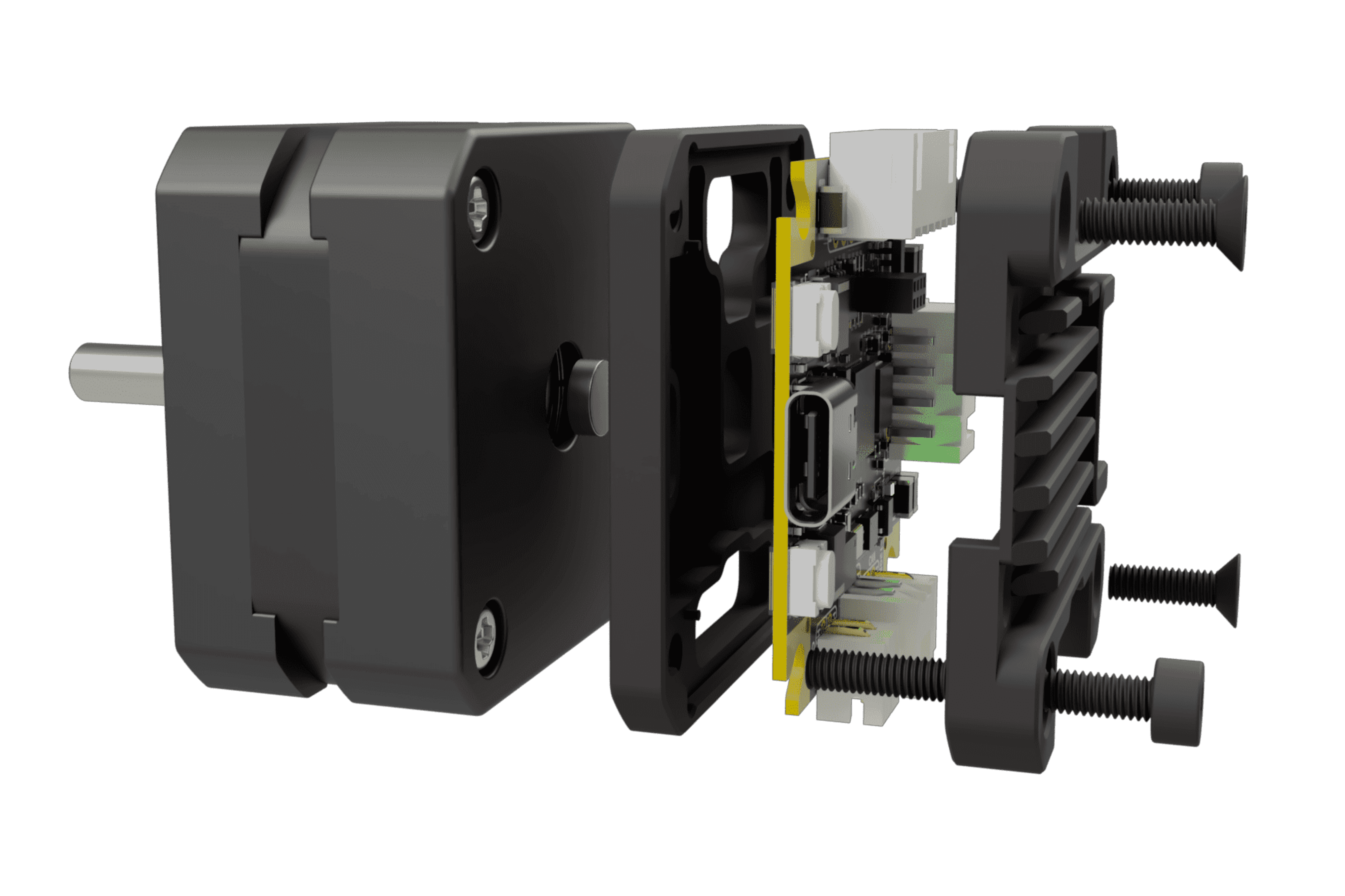
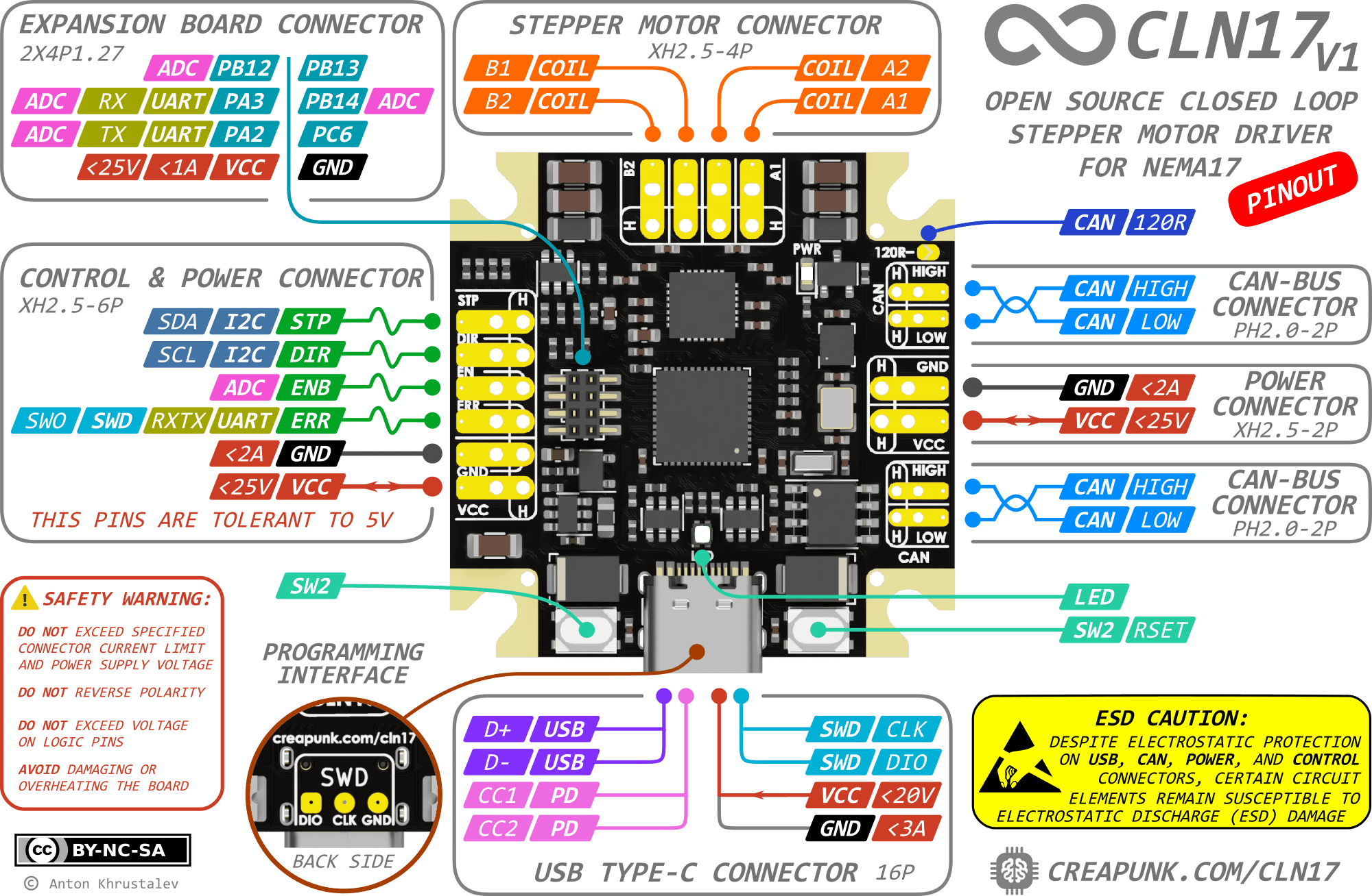
Board Diagram
Key Features | All Features
- 🕹️ Closed-Loop Control: Enables precise motion in challenging conditions.
- 💪 Adaptive Torque Control: Optimizes energy efficiency, reduces stress, and extends motor lifespan.
- 🧩 Reliable Operation and Enhanced Safety: Ensures reliable operation and protects users from potential harm.
- 🛡️ Modular Concept: Provides flexibility and cost-effectiveness through various configurations and expansion boards.
Key Specs | All Specs
- 🔌 Wide Input Voltage Range: 5-25VDC with reverse polarity and surge protection
- ⚡️ Powerful Motor Control: 1.4A RMS current per phase with up to 2.5A peak and up to 1/256 microstepping
- 🚀 High-Performance MCU: STM32G431CB Arm Cortex-M4 running at 170MHz with Classic EN/DIR/STEP interface, CAN-Bus, I2C, UART and USB Type-C with PD2.0 support,
- 🔒 Compact and Durable Design: 38x38mm PCB, with optional aluminum housing for heat dissipation and mechanical protection and minimal height of 7.5mm (10mm with connectors)
Applications | In-depth
- 🎓 Learning Platforms
- 🛠️ CNC Machines & 3D printers
- 🤖 Robotics & Automation Systems
- 🤝 Collaborative Robots
- 🔭 Camera & Telescope Stabilization Systems
- 🔬 Laboratory Equipment
- 🏭 Industrial Motion Control Systems
- 📳 Haptics & Force Feedback Systems
What is the project's status?
There are numerous updates planned for the documentation, including the publication of articles on related topics. Alsowill be provided insights into development process, announce new versions, introduce new features, and much more. Here's a concise breakdown of major and immediate updates:
✅ Completed:
- Project Conceptualization: The initial idea and blueprint of the project.
- First Prototype Development: Crafting the initial version of our product.
- Design Completion: Finalizing (or nearly finalizing) the product's design.
- Final Prototype Testing: Evaluating the last prototype to ensure functionality and reliability.
- Wiki and Specifications: Developing a comprehensive wiki and detailing the product's specifications.
🔜 In Progress:
- Hardware Documentation: Providing essential information and guides about the hardware components.
- Library for TMC2209: Developing a STM32 library to manage all TMC2209 registers using UART communication.
- Library for TLE5012B: Crafting a STM32 library for interactions with TLE5012B registers via SPI.
- Basic Driver Function Code: Producing the foundational source code for executing the product's essential operations.
📅 Scheduled:
- PowerDelivery Support Library: Working on a library that will support PowerDelivery functionalities.
- CLN17 Lite: Simple and cheap version for basic tasks (CAN-FD, IMU excluded)
- CLN17 Pro: Advanced version with higher currents and voltages (TMC2240 based)
- CLN234 Version: Developing a variant that can control NEMA23 and NEMA34 motors, supporting up to 55V 10A (TMC5160 based)
Should there be significant interest, the project will establish Kickstarter Campaign and its own store to cater to the entire community's needs!
Components
- 1 × CLN17 PCBA For control the motor
- 1 × NEMA17 Stepper Motor The motor as it is
- 1 × Diametrically magnetized magnet D5xH2mm To determine the shaft orientation with a magnetic encoder
- 1 × Aluminum enclosure For positioning, securing, protecting and cooling the board
- 2 × DIN912 M3 For securing to the motor
Project Logs
Collapse
-
The Journey: Functional Prototype
Anton Khrustalev • 09/12/2023 at 13:14 • 0 commentsAfter an extensive development process which involved numerous design iterations and reconsideration of implementation methods, the updated project version that encompasses all concept ideas has been released!
Compared to the previous version, the PCBA is more:
- Compact
- Powerful
- Functional
- Equipped with numerous safety features
![]()
It has now evolved from being just another driver to becoming a powerful tool for education, development, testing, and system modeling.
Does it work? The short answer is yes. However, diving deeper, things get a bit more complicated.
From a hardware perspective, there are a few minor issues, which fortunately don't have an impact on the primary functionality. These known issues include:
- Incorrect polarity of the power indicator LED;
- Not stable behavior of the buck DCDC converter at voltages below 6V
Apart from these, all other driver functions operate correctly.
On the code side of things, it's a different story. A vast amount of work is still needed to release the complete driver control library that would unlock its full potential. But there's hope that it's just a matter of time.
-
The Journey: Concept Challenges
Anton Khrustalev • 09/12/2023 at 12:03 • 0 commentsBased on the experience and ideas acquired during the prototype development, a final vision of the project and its functionalities has been formed. Below are the key challenges:
- Quiet yet Robust Driver: Designed to deliver core motor control functionalities unhindered by hardware constraints. This driver is intended to be an off-the-shelf solution to minimize the computational load on the microcontroller and mitigate risks, leveraging the inherent safety features of pre-built solutions.
- Support for Standard Interfaces: Incorporates USB for computer connectivity, CAN-Bus for communication within industrial systems, Stepstick for compatibility with legacy systems such as 3D printers, and UART and I2C for interactions in embedded environments.
- High-Speed Microcontroller: Equipped to handle concurrent tasks such as position calculations, real-time encoder-based position monitoring, processing of external commands from various interfaces, and other user-defined tasks.
- Compatibility with Expansion Boards: Ensures the provision to integrate additional boards to accommodate any functionalities not originally addressed.
- Efficient Power Delivery: Guarantees compatibility with widely-used power sources or power banks.
- Optimal Protection: Shields against potential hazards like electrostatic discharges, current overflows, voltage spikes, and more.
- Integrated IMU: Facilitates the detection and compensation of resonances or vibrations while continuously tracking the current position.
- Compact Design: Crafted to seamlessly integrate into devices where space is a constraint.
- Cost-Effective and Modular Structure: Tailored for swift customization based on specific requirements.
There are many other smaller nuances that can be enumerated, but more on that later! You can also read the foundational principles to get a clearer picture.
-
The Journey: Concept Prototype
Anton Khrustalev • 09/12/2023 at 10:33 • 0 commentsIn March 2022, while working on a laboratory robot designed for handling test tubes, the idea of using a closed-loop driver came up. This driver needed to be:
- Compact
- Feature minimalistic wiring
- Offer precise and repetitive positioning
- Exhibit unwavering reliability
Sadly, no existing solutions fit the bill. Some were inadequate due to size, others lacked the necessary features or interfaces, some had proprietary code that disallowed modifications, and still, others were either unavailable due to component shortages or had been discontinued. A detailed comparison of these alternatives can be found here.
Thus, a new vision was formed: To create a universal, powerful, and affordable driver that would address all challenges related to controlling a stepper motor.
![]()
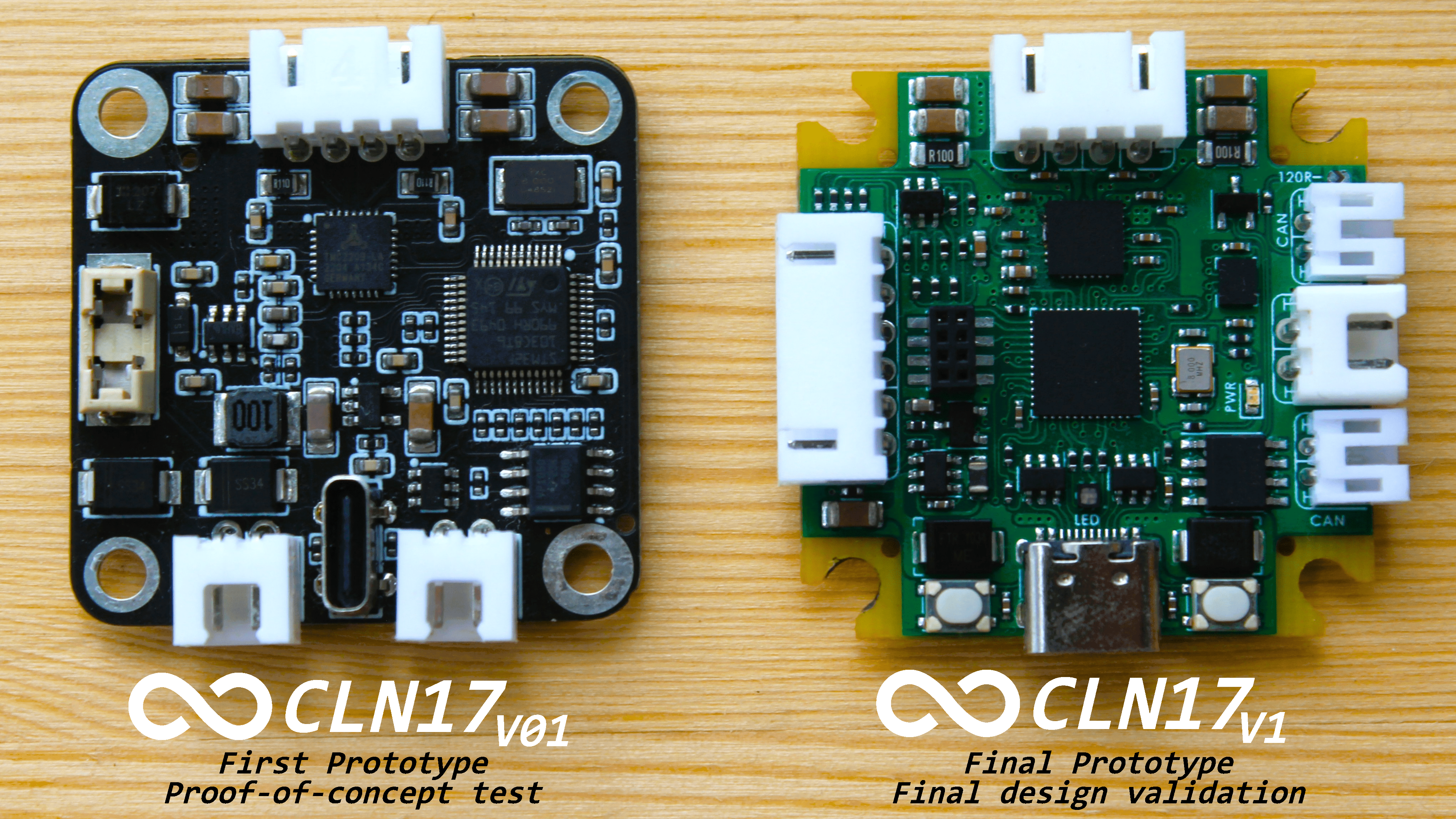
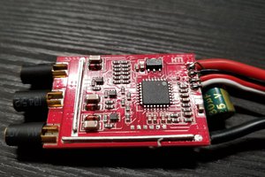
By September 2022, the first prototype driver was born. Key components included:
- Standard CAN-Bus and USB2.0 with QC support
- STM32F103 MCU
- TLE5012B encoder
- TMC2209 stepper motor driver
However, there were critical setbacks. While it did feature a Type-C port, it relied on Quick Charge (QC) for power, which hampered its flexibility. Another significant limitation was that the controller could not operate the USB and CAN-Bus simultaneously, leading to developmental troubles. A few minor problems arose but were quickly fixed with a soldering iron.
Predictably, this prototype did not achieve all its intended functions, underscoring the need for a revised driver version. This initial setback only strengthened the determination to design a comprehensive stepper motor control solution.
Build Instructions
Collapse
-
1Complete Project Documentation
All the latest project documentation can be found at creapunk.com/cln17
-
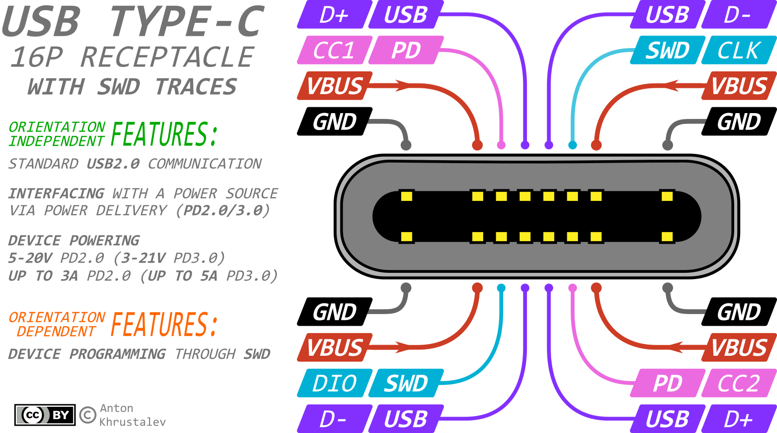
2Note about USB Type-C and board programming
In many small-scale embedded projects, the Type-C connector has historically seen limited use. However, there's a noticeable shift towards its adoption in recent times.
For the most part, Type-C acts as an up-to-date substitute for the now-obsolete Mini-USB or Micro-USB connectors. Their primary roles have been to provide 5V power and to function as a USB2.0 interface. Let's sidestep the frequent oversight by some developers who forget to incorporate the 5.1k resistors.
Yet, the utility of Type-C extends far beyond merely replacing aged connectors!
Note: This discussion excludes Type-C configurations that necessitate USB3.0 or the 24-pin connector due to their intricate design.
A popular adaptation of Type-C is the 16-Pin variant:
Pins Usage 8 pins Power (4 for GND and 4 for VCC). There's a potential limitation to 3A – this requires confirmation. 4 pins Orientation-independent USB 2.0 (2 each for D+ and D-) 2 pins CC1 and CC2 (Configuration Channel) for PowerDelivery communication 2 pins SBU1 and SBU2 (SideBand Use). Usually dormant, except in 'alternate mode' or specific Audio Accessory Modes. Employing PowerDelivery can yield voltages and currents ranging from:
- 5-20V at 5A (max 100W) for PD2.0
- 3.3-21V at 5A (max 100W) with 20mV steps in PPS mode for PD3.0
- 3.3-48V at 5A (max 240W) with 100mV steps in PPS+EPR mode for PD3.1.
However, two pins in the connector – SBU1 and SBU2 – often remain untouched. They're designated for 'alternate modes' that rely on USB3.0 signaling lines. Since many projects bypass USB3.0, these pins stay dormant. But consider the potential: what if we repurpose these pins for debugging or programming? Imagine using them for the SWD or UART interfaces, both of which require just two lines! For example
![]()
In terms of compatibility, the Type-C standard dictates that the impedance of inactive SBU lines should exceed 950kOhm. With CMOS-based communications (like UART and SWD), this specification is almost always met. Additionally, if a Type-C cable lacks USB3.0 support, it likely won't carry SBU signal lines, eliminating potential concerns. And given the resilience of UART and SWD protocols, coupled with their data integrity checks, inadvertent mishaps are unlikely.
Advantages:
- Single connector on the board, ensuring reliable contact.
- Eliminates the need for bulky programming pads, especially in micro-projects.
- Debugging flexibility with extended cables.
- Firmware updates without having to disassemble the device.
Drawbacks:
- Mandatory attention to Type-C orientation since signaling is orientation-specific.
This is a raw note, will be corrected late
Linked project: #SWD over USB Type-C: New way of programming boards
Enjoy this project?
ShareDiscussions

Thank you! The project is still in the works, so the release of source files and software is planned after successful tests. Follow updates on this page or in the Discord community!
 Anthrobotics
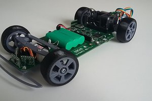
 AdaCore
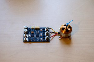
 Maakbaas
 Zdenek Hurak
Hey, great project! Where can I find the code it is not on gihtub.