Beko Pharm
Primary Buffer Panel v2 (the good)
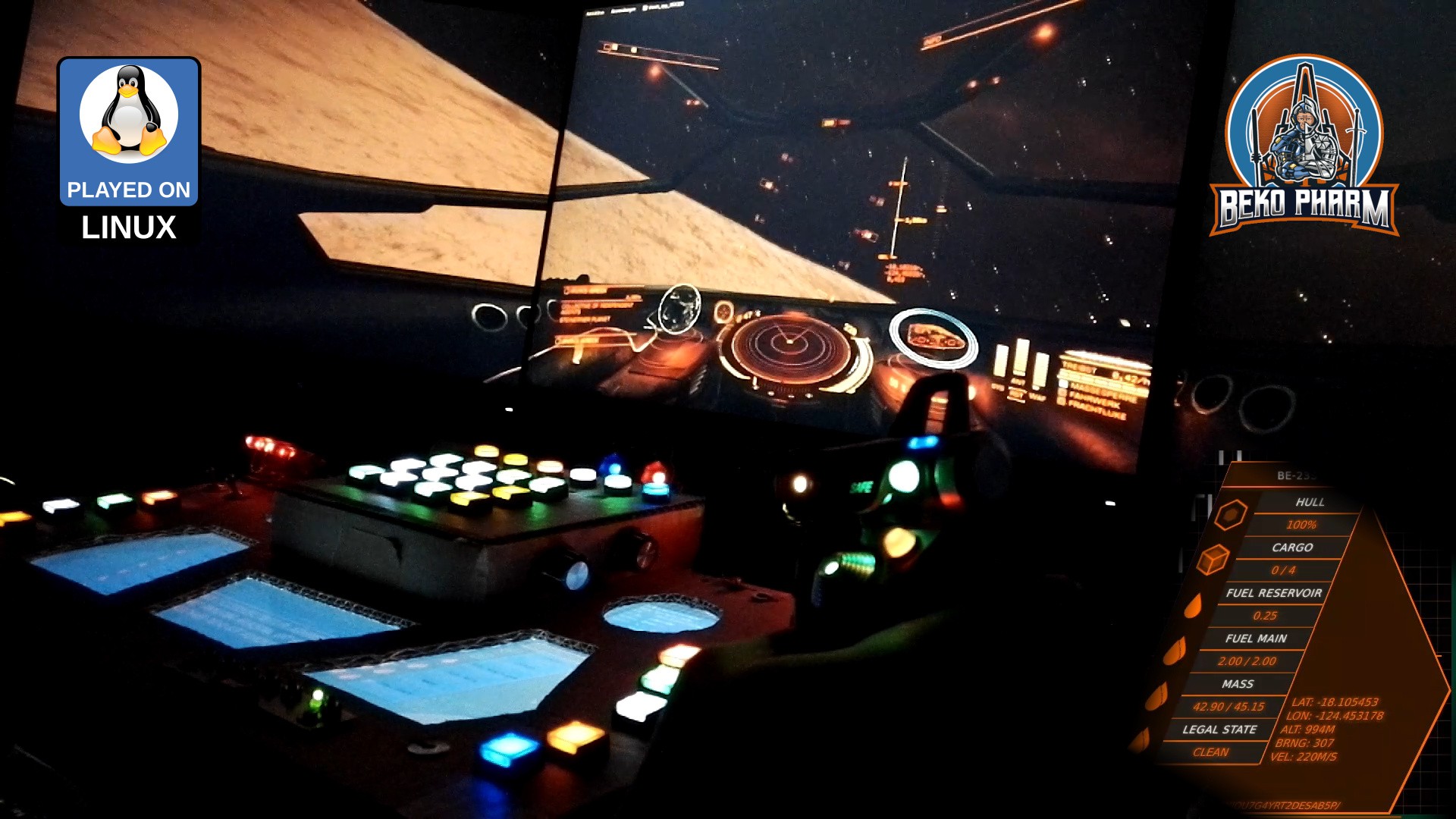
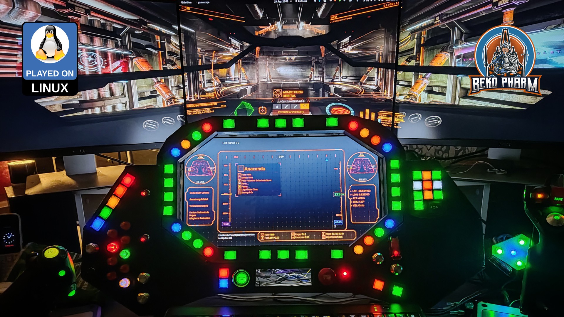
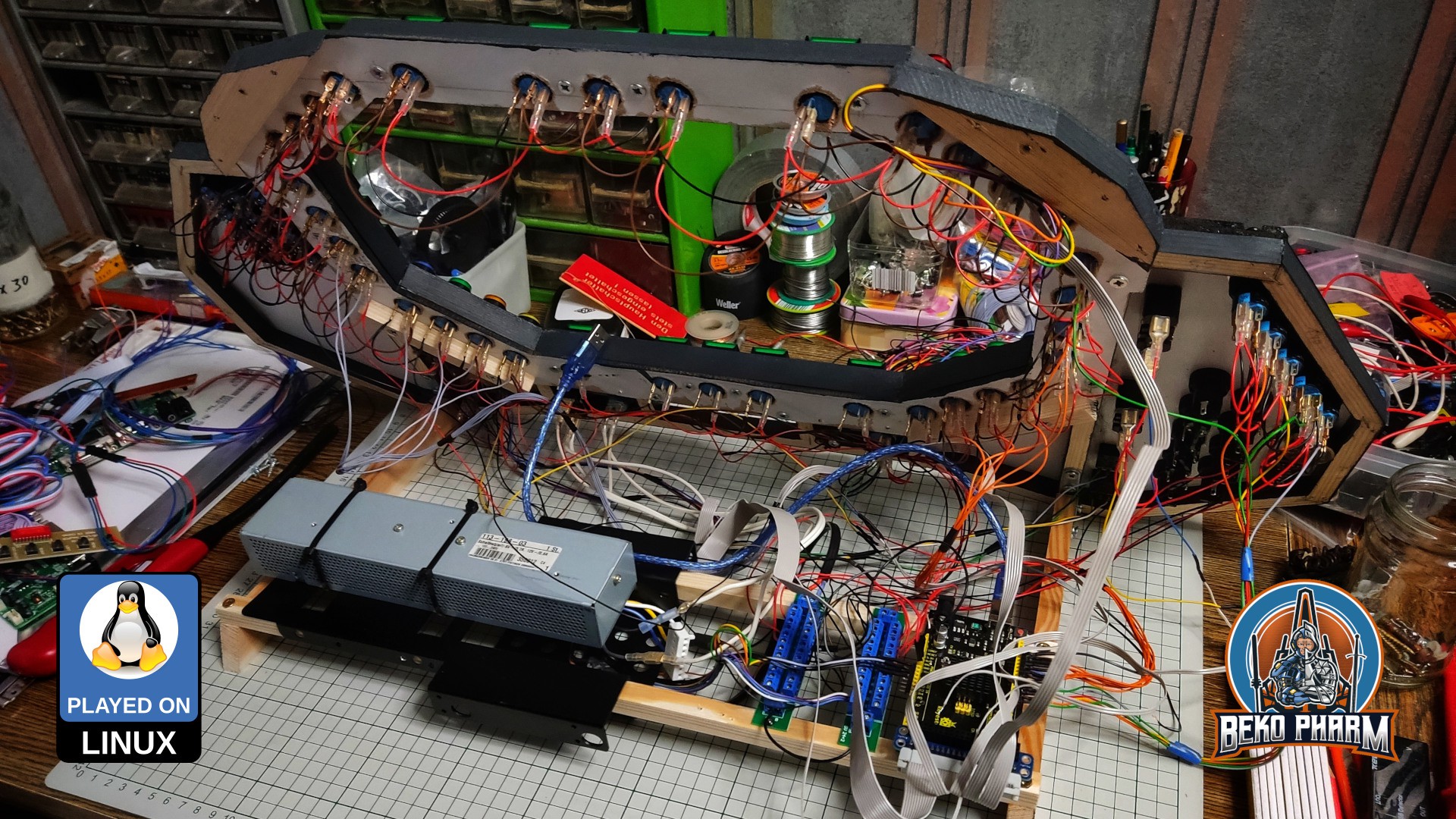
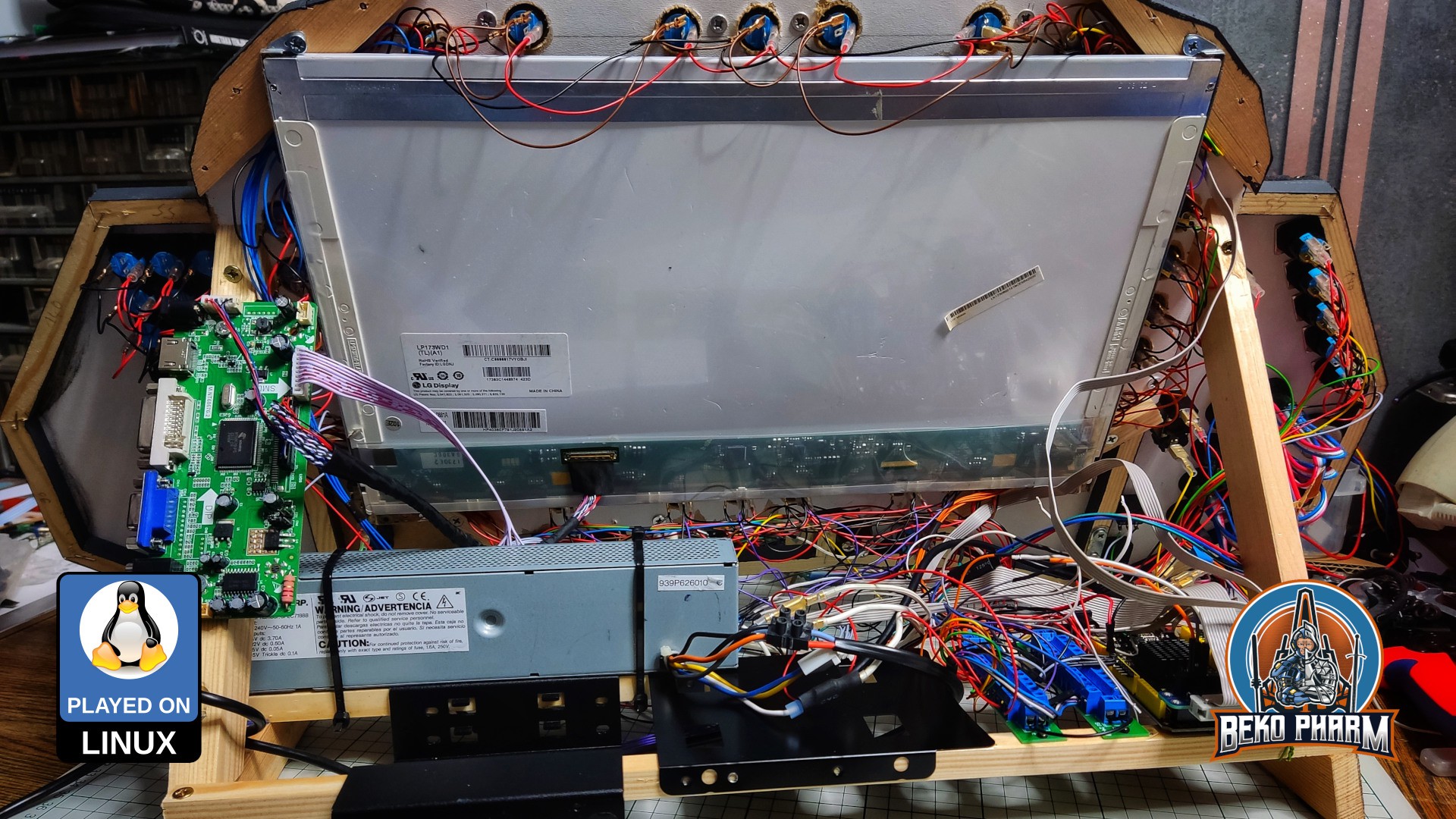
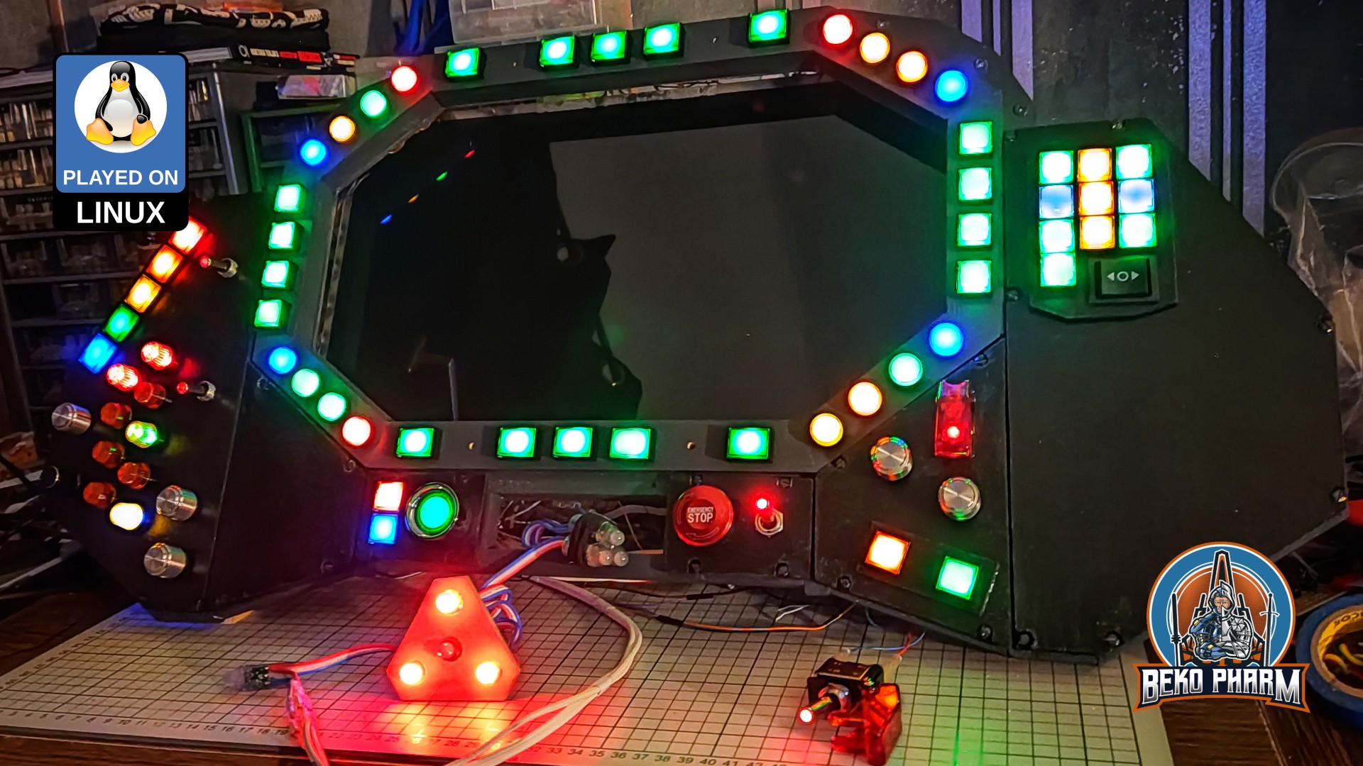
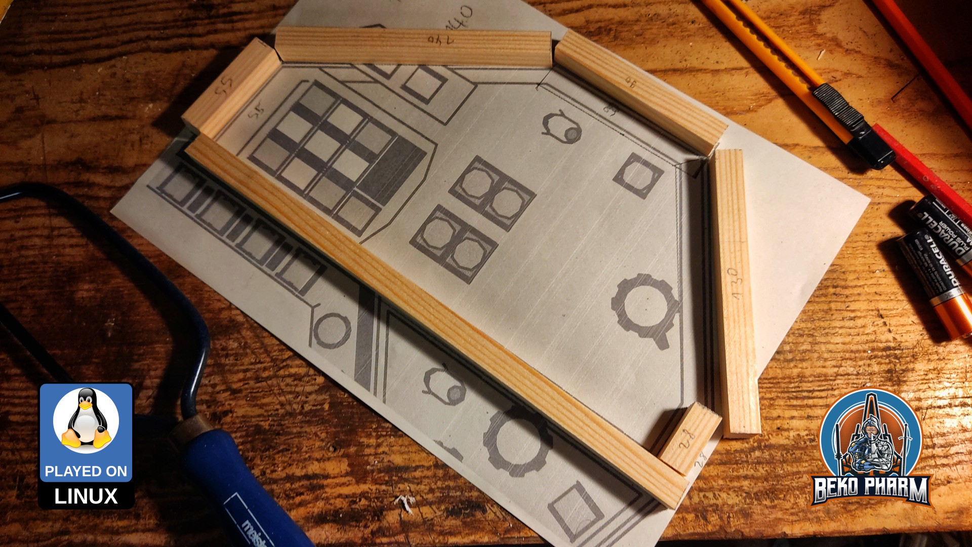
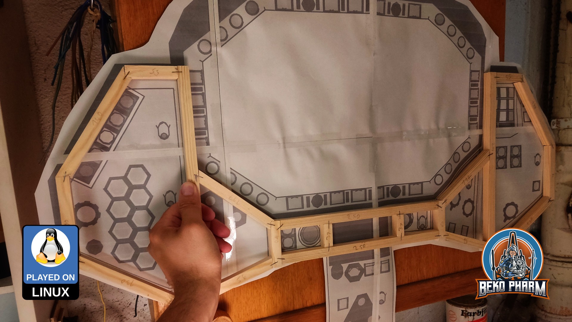
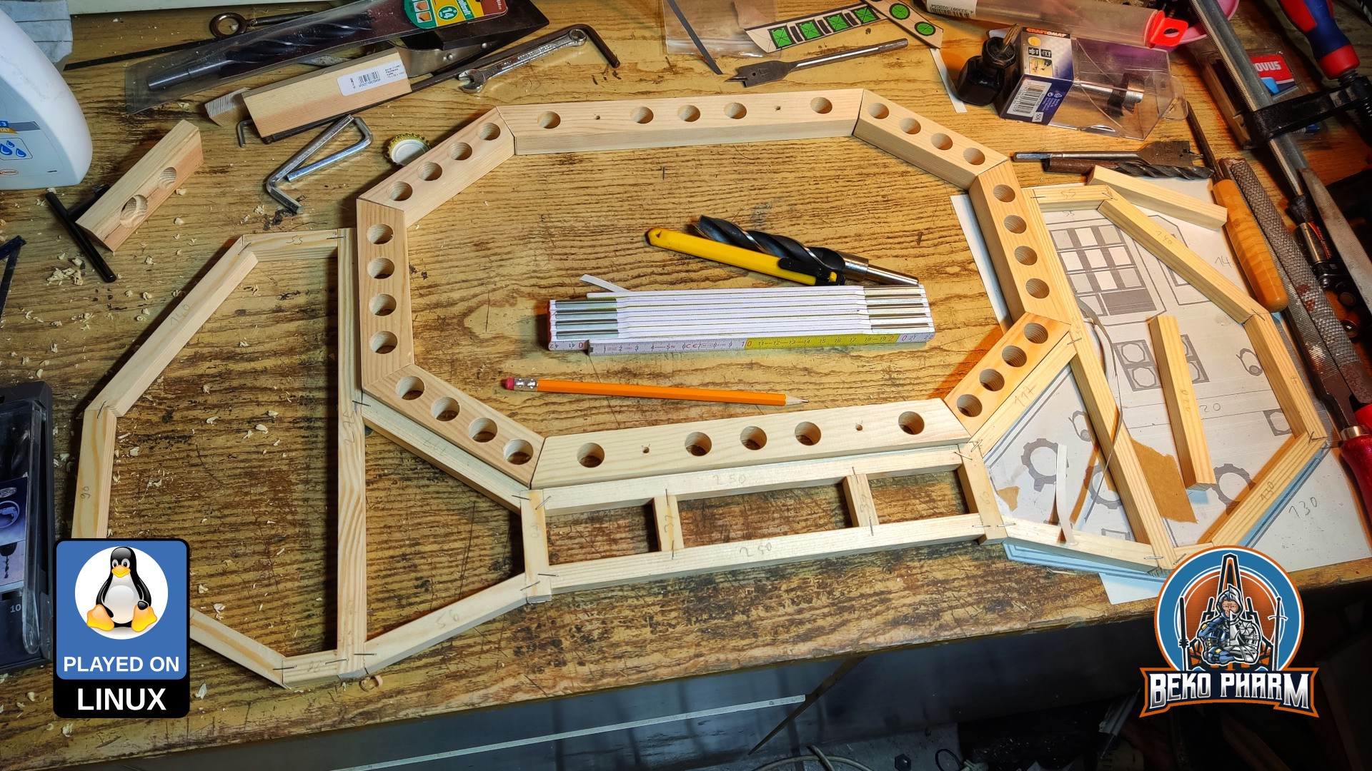
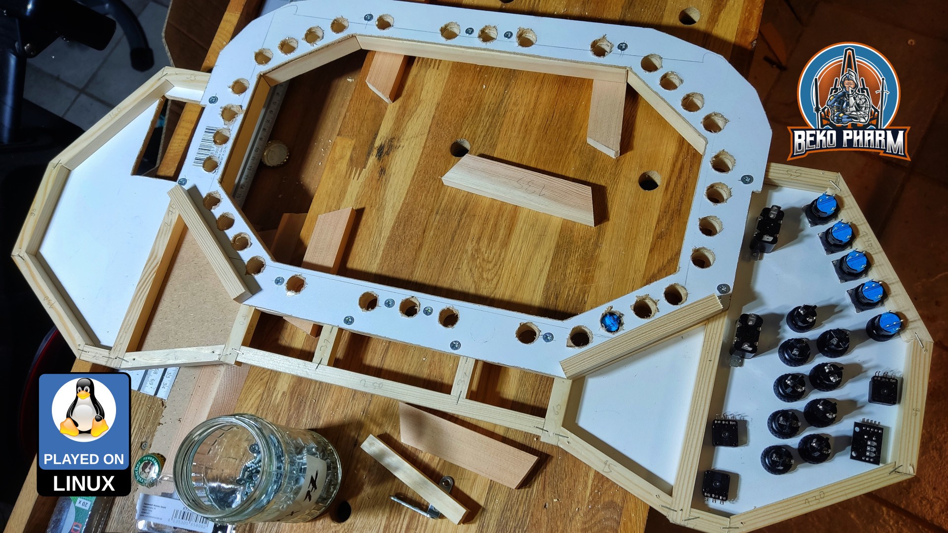
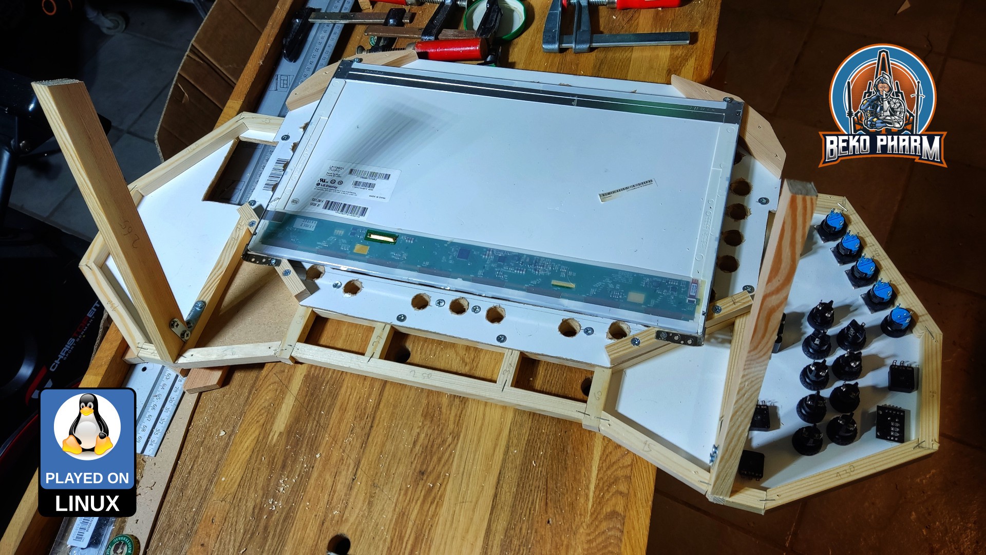
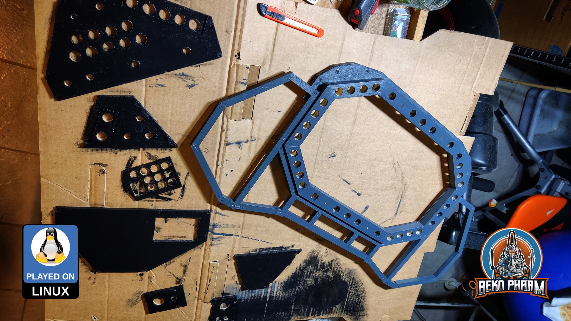
The second version of the Primary Buffer Panel was built directly on the basics developed for version 1. This time it features a wooden frame though and is no longer just cardboard. The idea is to eventually incorporate the panel in a full featured simulated cockpit [in the far future].

It’s design is based on a VF-1 Valkyrie cockpit of the Macross franchise - or Robotech as it is known in some parts of the world (but we don’t talk about this here).
Originally posted at https://simpit.dev/version-2/


 David Boucher
 Michael Gardi
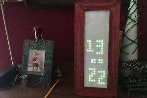
 Jorj Bauer